Fogger Controller
Copyright Tomi Engdahl 1999
Introduction to foggers
Foggers used to generate fog and smoke effects operate by heating a special fogger fluid. They consist of a heting element which is kept in the right temperature using a thermostat. When the operator want to generate smoke, he/she presses the controller button which starts the pump which pumps fog fluid to the heating element. When smoke fluid enters the heating element, in starts to evaporate and produce smoke.
Cheap foggers usually come with only a simple one button controller. This controller is useful for smoke starting smoke effects on user request, but is not very useful if you want to keep up a constant level of fog on the room. This is where more expensive foggers come to play, because they come usually with a controller which allows you to generate fog at some slow constant adjustable rate.
If you happen to own a cheap smoke machine and happen to want this kind of functionally only found on expensive models, the circuit shown on this web page might turn to be useful to you.
Some details of SUPERSTAR fogger
SUPERSTAR FZ-920 SMOKE MACHINE uses 3 pin IEC connector for the fogger remote controller. This kind of connector is used on many computer equipments for connecting grounded power to the equipment. In this application this connector is used in quite nin-traditional way. The following circuit diagram shows the circuit diagram of the remote controller which came with the fogger:

Some remarks of the remote controller wiring:
- The use of the wires is quite non-traditional (ground pin used for other thing than safety ground !)
- When switch connects GND to the N wire, the smoke machine puts out smoke
- When there is voltage between L and GND, the lamp in the controller (GLIMM lamp and resistor) lights to show that fogger is heating up.
- Because of this special wiring is is dangrous to connect anything else than the original coontroller to the fogger.
- It is potentially dangerous to connect this controller to a normal mains outlet, because pressing the button will short one line wires to ground.
To make this circuit remotely controllable, all I had to do was to add relay on parallel with the existing button on the controller and make a circuit which controls that relay.
NOTE: The wiring of the controllers of the smoke machines can vary from manufacturer to manufacturer. The controller of your smoke machine might be entirely differently wired and might even use different type of connector.
Fogger controller circuit
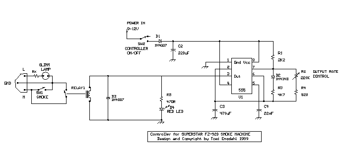
The following circuit shows the circuit diagram of the advanced smoke machine controller I have used with my SUPERSTAR FZ-920 SMOKE MACHINE:

Technical specs
- Designed to be used with SUPERSTAR FZ-920 SMOKE MACHINE and replaces the original remote controller
- Operation voltage: 9-12V DC unregulated wall wart, 200 mA current rating or more
- Smoke burst length: 2 seconds
- Time between smoke bursts: 0.3-60 seconds
Circuit operation
When the power is connected to the circuit by turning on SW2, RELAY1 get energized for the time it get for it to load C3 through R1 and R3. After that the relay get de-energized, C3 gets discharged through R2 and R4. The setting of R2 determines the discharge time which can be up to 1 minute. After C3 is discharged, the releay is activated. C3 charging starts again. The charging of C3 take around 2 seconds. After that relay is de-energized and C3 discharge starts again.
Every time the relay is energised, the smoke machine is set to push out smoke. The time it puts out smoke is around 2 seconds, which was adequate to put out enough smoke fluid that the smoke machine puts out smoke for a brief amount. The iime between the smoke output is adjustable from practically constant smoke output to one minute pause between brief bursts of smoke.
Component list
R1       2.2 kohm
R2       220 kohm potentiometer
R3       4.7 kohm
R4       820 ohms
R5       470 ohms
D1       1N4007
D3       1N4148
D3       1N4007
D4       RED LED
C2       220 uF 25V
C3       470 uF 16V
C4       22 nF
IC1      LM555
RELAY1   Relay with 12V coil and 250V 4A contacts
SW1      250V 4A switch
SW2      General purpose low voltag switch, at least 1A current rating
GLIMM    GLIMM lamp with internal current limiting resistor (Rx) for 230V (panel light)
CON      Male 3 pin IEC mains connector
Tomi Engdahl <[email protected]>


