


Simple LED dimmer circuits
The circuits on this page are designed to very simple, built with minumum number of components.
The downside of them is that their efficiency is not good (considerable power is lost in control circuit).
Dimmer controller for 1W LED or 3x1W RGB LED
This circuit takes 0-10V control voltage input and is designed to run on 1W white LED. The + power needs to be connected to 12-15V DC power (up to 350 mA current consumption).
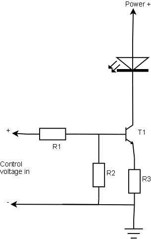
Component list:
R1 = 1.2 kohms 0.25W
R2 = open circuit (no resistor)
R3 = 33 ohms 5W
T1 = BDW93
The circuit works in such way that 0V makes LED to be off and 10V it to be completely on. Dimming works at approximate voltages between 1.3V and 9V. You should not need any heatsink for the transistor. Most of the power loss (maximum 10V * 350 mA = 3.5W) happens on the resistor. The transistor T1 is a high current gain darlington transistor (gain around 750-1000) which makes sure that the circuit does not take much control current from 0-10V control voltage source.
NOTE: The circuit efficiency is not good, because for driving a 1W LED you would take more than 4W from the power source and more than 3W of it would be lost on the dimmer circuit when LED is fully on. The efficiency is around the same also at other dimmer settings (around 3/4 of the power lost on dimmer circuit). This is the price of the simplicity.
Controlling more than one LED
It is possible to use this circuit to run many LEDs in series connected in series in place of the one LED in the circuit. If you are driving more than one LED, you will need a higher control voltage power source (around 3-4V higher for every added LED) and a heatsink for the transistor.
Controlling RGB LEDs
By building three of this type circuits you can control easily RGB LED that has there 1W LEDs in it.
Adaptation for lower power supply voltage
The voltage loss one the T1 and R3 can be reduced by changing to use the following component values:
Component list:
R1 = 2.2 kohms 0.25W
R2 = 2.2 kohms 0.25W
R3 = 15 ohms 2W
T1 = BDW93
Now the voltage loss on T1 + R3 is now approximately 5V maximum. This means that you can power the whole circuit (dimmer + one LED) with 8V or higher power supply voltage. Please note that if you use original 12V power supply, you will need a heatsink for T1.
Adaptation for 0-5V control voltage
Component list:
R1 = 1.2 kohms 0.25W
R2 = open circuit (no resistor)
R3 = 15 ohms 2W
T1 = BDW93
Remeber to put heatsink for T1.
Warning: Higher than 5V control voltage fed to the input of this 0-5V circuit can cause too much current to flow to to LED, which can destroy the LED. If you have risk for that, you can put a 5.1V zener diode in place of R2 to make sure that the control voltage that goes to T1 base will never get considerable higher than 5V.
NOTE: This 0-5V circuit should be suitable to be used as LED driver for PWM controlled application. You should be able to put PWM signal (0V or 5V) to the control voltage input and control the LED brightness with the pulse width.
Dimmer for 1W LEDs driven with constant current source
This circuit is designed to be wired in parallel with a 1W LED powered with constant current power source. The idea is that when you want to dim a LED, this circuit will take some part of current that normally goes through the LED so it becomes dimmer. The constant current source will always give same current to LED + dimmer circuit, so more the dimmer circuit takes less is left for LED.
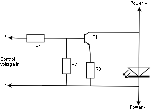
Component list:
R1 = 2.2 kohms 0.25W
R2 = 2.2 kohms 0.25W
R3 = 4.7 ohms 2W
T1 = TIP41A
NOTE1: This circuit is designed only for applications which use a real contstant current power source. If your LED driving circuit is not a real constant current source then this circuit does not work properly and you risk damaging your LED power source.
NOTE2: The circuit works in opposite to normal 0-10V dimmers. Control voltage at is 0V makes LED to be fully on. Control voltage of around 10V makes LED to be off. Dimming works at voltages between them.
This circuit can also used in application where there are many LEDs in series. You can put all the LEDs you want to dim in place of the LED in this circuit. Then add suitable heatsink for the transistor (capable of handling the power of those LEDs). It is also possible to have non-dimmed LEDs on the same LED string, just connect thise LEDs that need to be at full brightness outside of this circuit (between circuit and power- or power+). In this way you can mix both full brightness LEDs and dimmed LEDs on the same LED circuit powered by the same constant current LED power supply.
<[email protected]>