


Simple microphone preamplifier
Design and copyright Tomi Engdahl 1997,1999
Summary of circuit features
- Brief description of operation: Simple microphone preamplifier
- Circuit protection: No special protection circuits used
- Circuit complexity: Very simple one transistor circuit
- Circuit performance: Amplification 35 dB, flat frequency response from 20 Hz to 20 kHz, quite poor distortion performance figures, a little bit noisy
- Availability of components: Uses common and easily available components
- Design testing: I have built few microphone preamplifiers based on this circuit and theu have worked without problems.
- Applications: Interface dynamic or electret microphone to a line level audio input in HIFI amplifier or computer soundcard.
- Power supply: 9V battery, takes less than 10 mA current
- Estimated component cost: Electronics components than $10
- Safety considerations: No special electrical safety considerations.
Circuit description
This is a simple microphone preamplifier circuit which you can use between your microphone and stereo amplifier. This circuit amplifier microphone suitable for use with normal home stereo amplifier line/CD/aux/tape inputs. This microphone preamplifier can take both dynamic and electret microphone inputs (preamplifier provides power foe electret microphone elements). The idea of this circuit is to keep the design as simple as possible to be easy to build. That was my goal when I needed a simple external microphone preamplifier for my mixer. The performance of the circuit is nothing superior but can be used with many not so serious projects.
The circuit is a simple one transistor amplifier with amplification of about 30-40 dB (depends on transitor, temperature and voltage). The dynamic mic input is just a simple one transistor amplifier circuit with nothing special in it. LED D1 is in the circuit to show that the circuit operates. The voltage drop caused by LED (around 1.8V for RED led) has been taten in account when designing the amplifier circuit built around Q1. Resistor R4 and capacitor C5 make a filter to filter out possible noise from battery or other power source which is used to feed this circuit. Capacitors C1, C2 and C3 are used to block the DC bias on Q1 base to flow out of microphone input to microphone (the polarity of all capactors is straigh line = + and curved line = -).
Electret microphone input has a resistor R1 fo feeding current through electret microphone capsule when it is connected to the electret microphone input. Electret microphone needs some current (about 1 mA) flowing through it to operate, because there is a small amplifier circuit inside the microphone capsule. This circuit is suitable for all typical cheap electret capsules which available from any electronic component shop. Because electret microphones have higher signal level output, it is quite easy to overdrive the amplifier when you shout to electret microphone.
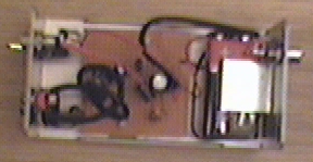
The circuit is bet to build to a small metal box like in the picture above. Put the 9V battery inside the case too. Battery power and metal box keep external noise and interference sources away. I used standard 6.3 mm jack for dynamic microphone and 3.5 mm mono jack for electret micrphone both installed to from, panel of the metal box. The LED and power switches are also installed to front panel.
Measured specifications from protype
- Frequency response: 20 Hz to 20 kHz +-1dB
- Noise level (A-weighted): -85 dBm
- Amplification: 35 dB
The bass frequency attenuation is caused by the microphone preamplifier circuit. The high end attenuation is caused by Sound Blaster 16 card. As seen in the measured performance, the microphone preamplifier is suitable for speaker measurements made using suitable measurement software and sound card. Using this preamplifier connected to line level input the problems caused by poor microphone preamplifier in many sound cards can be avoided.
Component list
R1      4.7 kohm
R2      220 kohm
R3      2.2 kohm
R4      120 ohm
C1..C4  10 uF 16V electrolytic
C5      100 uF 16V electrolytic
D1      Red LED
Q1      BC547B
SW1     on/off switch
If you can't find all the components on the shop near you take a look at component replacement tips. If you happen to have hard time finding BC547 transistor, you can use 2N2222 transistor instead. The circuit has been reported to work well with it also (although there might be some slight performance changes though, I have not tested and mearured the circuit with 2N2222).
Modification ideas
If you plan to use this circuit with a soundcard electret microphone which has 3.5 mm stereo plug, then you have modify the circuit to make it work work this type of multimedia microphone. You don't have to make many changes: just replace the 3.5 mm mono jack with stereo jack. In the original circuit R1 goes to the tip of the microphone connector, but now you connect R1 to go to the ring of the connector.
If you want an adjustable output signal level for the microphone preamplifier you can add this quit easily by connecting one 10 kohm logarithmic potentiometer to the circuit output in the following way:
  From mic amp >------+
  output              |
                     | |10 kohm log
                     | |<---------------- Output
                     |_|
                      |
  Ground -------------+------------------ Ground
This circuit allows adjusting the output level between zero and the maximum
microphone preamplifier amplification.
How the amplification is compared other amplifiers
AVID MC-1 Universal Multimedia Microphone Amplifier has the following specifications:
- Level constrol range: 10 dB
- Amplification for dynamic microphone: 46 dB to 56 dB
- Amplification for electret microphone: 16 dB to 26 dB
Questions and answers
What is the difference between MIC and LINE level?
Level refers to the relative strength of the signal and is measured in decibels. LINE level sources are much-amplified signals over MIC (microphone) level signals. Line level is usually between -10 to +4 dbm in strength while MIC levels are normally -60 dbm.
What is meant by "low impedance"?
Impedance is an electrical term that refers to how much a device impedes the flow of current and is measured in ohms. While there is no set standard, low impedance usually refers to a range of between 150 and 800 ohms. Most professional audio microphones are low impedance. This amplifier circuit designed to work with any low to medium impedance source.
How can I change the amplification of the circuit ?
The amplification factor in this circuit is determined mainly by the characteristics of Q1 and value of R2. The circuit is designed for quite optimum performance (for boing such simple circuit) and it does not pay to ry to modify it much. If you wan to try modification, you can change the value of R1 between something like 100 kohms and 1 Mohm to get somewhat different performance.
If you simply want to reduce output level, use the modification idea described earlier in this article. If you need more apmplification, then try some some other circuit with nore transistors.
Can other transistor types used ?
I have not tried this circuit with any other transistor type myself, but it should work quite well with a large set of small signal transistor which are quite similar to BC547B. Using other transistor type can vary the amplification factor, noise level and distortion figure. If you have problems in getting the circuit to works with some trange transistor type, you can try changing value of R2 to something between 100 kohm and 470 kohm (somethign which works well).
According one comment I got a 2N2222 transistor would work well in this circuit without modifications.
If I want to build your microphone amp just for a dynamic microphone only, what portions can I leave out?
You can leave out R1, C1 and C2.
If I want to build your microphone amp just for a electret microphone only, what portions can I leave out?
You can leave out C3. All other parts of the circuits are need in this application.
Tomi Engdahl <[email protected]>