


Connect line-level signal to phono input
Copyright Tomi Engdahl 1997,1998
Circuit description
Introduction
Many amplifiers have phono inputs for connecting record players to the amplifier. Phono input is designed to take a up to few millivolt signal from phono pickup and amplify it. The amplifier stage does also some equalization based on standardized RIAA curve. The RIAA reproduction curve:

That RIAA equalization is used in the playback to reduce the high pitch noise and maximize bass dynamics in the phono playback. The audio material which is rocorded to the record has been pre-equalized so that the frequency response of the whole chain from the mixing desk to your speaker will give flat frequency response.
Nowadays phono inputs are largely unused because vinyl record players are getting rare. This circuit is is a simple converter to convert line level signal (0..1 V) to phono input levels (0..5 mV), which makes it possible to use those inputs as an extra line input. This circuit does the level conversion, impedance matching and inverse RIAA filtering. The inverse-RIAA filtering network in this circuit is needed, because all phono inputs have RIAA filter in them.
Circuit specifications
- Input impedance: > 10 kohm
- Output impedance 470 ohms
- Nominal input signal level: 500 mV
- Nominal output signal level: 2.5 mV
- Attenuation: 46 dB
- Frequency response: inverse-RIAA
- Phono input compatibility: moving magnet and high output moving coil type inputs (= compatible with most receivers and integrated amplifiers)
Circuit operation
The circuit does two functions: signal level attenuation and inverse RIAA filtering. The signal attenuation is needed to convert the 500 mV signal to 2.5 mV signal. The inverse-RIAA filtering is needed to make the frequency response of the system flat (same equalization that is used when music is transferred to vinyl in the studio). The picture blow shows the frequency response of the ideal inverse-RIAA filter:

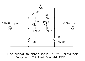
Circuit diagram
The picture below shows the circuit diagram of one channel. The other channel (for stereo) is identical. The circuit is so simple that you can easily build it by just soldering the components together and fit them to small metal box with the RCA audio connectors.
This circuit is a simplified version of circuit published in Elektor Electronics (T.Giesberts, Pick-up input becomes line input, Elektor Electronics, December 1995, page 99). The basic circuit idea is same, but my circuit is simpler and it does not use high-precision components. The performance is not the same, but I think that this circuit build even from 5% components is adequate for many purposes.
Component list
C1   2.2 nF
C2   1.5 nF
C3   1.5 nF
R1    68 kohm
R2     1 Mohm
R3   147 kohm
R4   470 ohm
and two RCA connectors
This part list is for the one channels described in the schematic. Usually you want stereo sound, in which case you have make two identical circuits: one for left channel and one for right channel.
Using the circuit
When you connect this circuit to your amplifier, set the phono input to MM or MD position (if it has a selector). Keep in mind that phono input is much more prone to pick up interference, because signal levels in it are much lower than in line level inputs.
General information on phono input
When choosing a cartridge for a given phono section, it is the "gain" or output that have to match.
- Typically almost all receivers, and most integrateds have standard 'low-gain' phono preamplifying sections (30dB to 38dB of gain typically). These require the use of either moving magnet cartridges (typically in the 2.0 to 5.0mv range) or high output moving coil types (generally 1.5 to 2.0mV output).
- The better preamplifiers (and the odd integrated or receiver) accept low-output moving coil cartridges - which have outputs of .2 to .9mV. These high gain phono sections will typically have approx 55dB to 75dB of gain.
- Very old tube amplifiers (50 years old) have had CERAMIC cartridge input which is very high input and accepts around 100mV signal level.
- MM (Moving Magnet) cartridges are designed to play into 47k ohms or higher input impedance. MM's will typically be loaded with capacitive loading in the pF range. Moving magnet phono cartridges have a typical output of ~3mv at 47K Ohm load. Movin gmagnet cartriges are the ones most commonly used.
- MC (Moving Coil) cartridges are typically designed to be loaded anywhere from 10 ohms to 1000 ohms.
- Ceramic catridges are high impedance signal sources. Their are not used nowadays because they were not "hifi quality".
Note to users of very old equipments
Some very old (typically TUBE) equipments had phono input designed for high impedance and high output level CERAMIC cartridge. These inputs were common 50 years ago, and disappeared with the introduction of stereo and transistors.
These inputs have no RIAA EQ (ceramic pickups are amplitude-sensitive, and the RIAA curve produces (very) roughly a constant-amplitude cut). A level of about 0.1 volt should be fine for those.
If you happen to have an equipment with CERAMIC cartridge input only, then you can't use the circuit described above. You should be able to do the conversion with much simpler circuit, just a 1:10 signal level attenuator, for example something like my speaker level to line level converter.
Tomi Engdahl <[email protected]>