


0-10V control for RC servos
This circuit takes standard 0-10V control voltage (for example from analogue light controlling desk) and outputs a standard 1-2 ms RC servo motors control pulse.
Summary of circuit features
- Power supply: 4-5V DC (same as for RC servo), consumes 15 mA of current
- Control voltage range: 0-10V
- Control input impedance: > 30 kohm
- Output control signal suitable for RC servo motors: 1-2 ms pulse with and pulse repeat rate is around 80 Hz
- Estimated component cost: less than 10 US dollars
- Circuit performance: Protototypes have worked very well
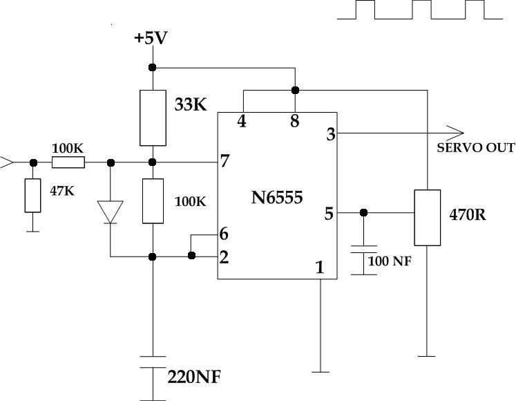
- Circuit is based on NE555 timer chip
Circuit diagram
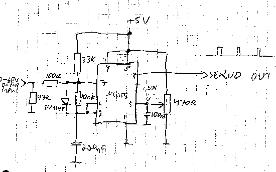
My original hand-drawn circuit diagram from my lab notes:
Component list
Component           How many

100 kohm resistor     2
47 kohm resistor      1
33 kohm resistor      1
470 ohm trimmer       1
1N4148 diode          1
220 nF capacitor      1
100 nF capacitor      1
NE555 timer IC        1
Using the circuit
I designed this circuit to control an RC servo from a light control desk that gave 0-10V control voltage out. In the light controlling desk the slider on the light controlling desk control the output voltage in 0-10V range. This circuit takes this control voltage in and generates a pulses that control a RC servo motor position based on this (those small servo motors that are used to control different things ar radio controlled cars, boats, planes etc..).
You need a suitable +5V power source to run this circuit. To use the circuit you connect RC servo to the circuit output to a suitable RC servo. The output of the circuit goes to control input pin in servo motor, servo motor ground goes to circuit ground and servo power input goes to suitable power source (can be the same 5V as used to power this circuit). The pinouts used on differnet servo motors vary, but the wire colors are generally so that black is ground, read is power and the third wire is the control input. In addition to this you need an adjustable 0-10V control voltage source. This can be a laboratory power supply, light controlling desk that give out 0-10V output, a 1 kohm potentiometer wired to 10V power source (wire ground to one end, +10V to other end take control voltage from the center). The control voltage will control the position of the RC servo motor connected to the output. When you change the voltage, the servo will move to the new position corresponding to the new control voltage value. 0V gets the servo to one extreme, and 10V to other end, and 5V puts the servo to around center position. That's how the circuit works.
Circuit construction
I have constructed my prototype to a piece of veroboard. No special construction considerations.
Circuit tuning
The 470 ohm trimmer in the circuit should be adjusted so that the pin 5 of NE555 IC receives a control voltage of around 1.6V. When a RC servo is connected to the circuit, you can slightly adjust the trimmer to adjust the center position and control range.
Circuit operation
In this circuit NE555 is configured as astable multivibrator. The main timing capacitor (220 nF) is always changed to the voltage level which is determined by the voltage on NE555 pin 5 (in this circuit that voltage is aroun 1.6V). When the timing capacitor is charged only with current coming through 33 kohm resistor, the charging takes around 2 milliseconds. When control voltage is appied to control input, the charging current increased when conrol voltage increases. When th econtrol voltage is 10V, the charging takes around 1 millisecond.
When the capacitor is fully charged, NE555 starts to discharge the capacitor through 100 kohm resistor. The discharging continues until the voltage has reached the half of the control voltage (1.6V/2=0.8V). The discharge time is determined by the resistor between NE55 pins 2 and 7. The 100 kohm resistor in this circuit makes this time to be around 11 milliseconds.
When the capacitor is discharged, the circuit start charging it again.
Tomi Engdahl <[email protected]>