


Mini pocket stroboscope
Designed by Tomi Engdahl

This circuit is a mini storoscope which you can make so small that it can fit into your pocket. The circuit is not very powerful, but is works out of two small 1.5V batteries for an hour constantly and maximum flash rate. The flash rate is variable from zero to about 10 Hz. Quite nice small device to have with you in parties to gain attention.
Summary of circuit features
- Brief description of operation: Flashing light at adjustable speed
- Circuit protection: No special protection circuits used
- Circuit complexity: Few modifications to an existing circuit
- Circuit performance: Works quite well
- Availability of components: The problem is to find a suitalble camera flas unit to take components
- Design testing: The orginal flash unit was modified until it worked as I want
- Applications: Gain attention in parties, very small scale stroboscope experiments
- Power supply: two 1.5V AA size batteries
- Estimated component cost: Few dollars + old camera flas unit
- Safety considerations: Electrical shock hazard, main capacitor has 500V charge and the trigger pulse is 4 kV, should be built to a well insulating case
How does a strobe light work?
A strobe light passes a brief, intense pulse of electric current through a gas, which then emits a brilliant burst of light. The gas is usually one of two inert gases, xenon or krypton, that emit relatively white light when they're struck by the fast moving electrons in the electric current. Because krypton and xenon atoms have a great many electrons and their electronic structures are very complicated, they emit light over a broad range of wavelengths. Thus the strobe emits a rich, white light during the moments while current is passing through the gas.
Supplying the enormous current needed to maintain the brief arc in the strobe's gas is done with the help of a capacitor. A high voltage power supply pumps charge to the cpacitor (usually to 200-600V range). You can often hear a whistling sound as this power supply does its work.
The capacitor plates are connected to one another through the gas-filled flashlamp that will eventually produce the light. However, current can't pass through the gas in the flashlamp until some electric charges are injected into the gas. These initial charges are usually produced by a high voltage pulse applied to a wire that wraps around the middle of the flashlamp or to the metal reflector near the flashlamp. A cascade of collisions quickly leads to a violent arc of charged particles flowing through the flashlamp and colliding with the gas atoms. The flashlamp emits its brilliant burst of light that terminates only when the capacitor's separated electric charges and stored energy are exhausted.
The circuit
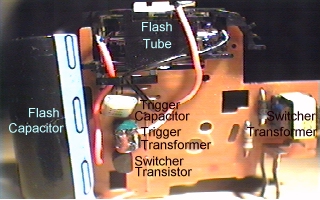
I build this mini strobosocope using compotents mostly taken from an old pocket camera flash unit and some cheap components I already had. On the picture below you can see the picture of the flash unit I used in my circuit (quite similar camera flash unit then can be bought from American Science & Surplus):
CAUTION - high voltage of camera flash unit can cause a nasty and possibly fatal shock. The energy storage capacitor can retain dangerous high voltage after power is removed from the board.
The transformers (T1 and T2), flash tube (X1), neon bulb (N1) and circuit board were from original flash unit. Nearly all other parts have been changed.

How the circuit works
Principle of the operation: Q1, R1, T1 and D1 form a DC-DC converter to convert +3V voltage from batteries to +200..+500V voltage which is charges the main flash capacitor C1. Resistor R4 and potentiometer P1 form a voltage divider and C2 is changed from that voltage though R3. When C2 reaches 70V voltage, the neon bulb N1 in the circuit starts to conduct and trigger the triac Q2. Thyristor causes C2 discharge through trigger transformer T2, which generates a short high voltage (2..4 kV) pulse which triggers the flash tube X1. Then main flash capacitor C1 discharges through flash tube and the tube generates a bright flash. The the charging of C1 starts again.
Where I got the components
Components T1, T2, D1, X1 and N1 were taken from old camera flash unit. There is nothing special in other components and they should be widely available. You can substitute Q2 with any suitable triac or thyristor which can withstand 400V and few amperes. You can also use any suitable power transistor (>2A and >40V voltage rating) as Q1 if you change the value of R1 to more suitable value fot that transistor. Anyway you can try other values for (100 to 2000 ohms) to tune the circuit to work best with the transformer you are using as T1 and the transistor you are using as Q1. The xenon flash tube X1 should work at 200-400V voltage range and trigger at 4 kV triggering voltage generated by T2.
Construction notes
If you are constructing this circuit remember that the voltage in the curcuit are at dangerous levels. Do not touch any parts at the high voltage side of the circuit when it is operating.
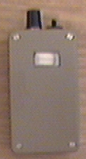
The circuit should be placed inside an insulating case like one above. There should be transparent plastic "window" in front of the flash tube. All parts should be well securated into the circuit board and the board should be well secured to the case. If you are using this at parties, some level of resistance to liquids and mechanical shocks is recommended.
Parts list
D1  1N4007
Q1  TIP 41A
Q2  MAC 216-4
T1  Switcher transformer taken from pocket camera flash unit
T2  Xenon flash tube trigger transformer
R1  500 ohm
R2  500 ohm
R3  4.7 Mohm
R4  220 kohm
P1  1 Mohm potentiometer (lin)
C1  470 nF 400V
C2  22 nF 200V
X1  xenon flash tube taken from pocket camera
N1  Small neon bulb (60V)
NOTE: You need a small stroboscope circuit similar to one I have used in the project to build this circuit. There are many necessary components (T1, X1) which you can buy from a component shop. The only way to get those components is to take them from the camera flash unit.
NOTE2: I have used MAC216-4 TRIAC (Q2) in the triggering circuit (might be hard to get nowadays, I don't know a good source for those ceuse the place I bought those is no longer in the business). Basically this circuit would also work nicely with simple thyristor, but I used TRIAC in this circuit because I had lots of those when I built the circuit but I did not have any suitable thyristors at home. Theoretically you should be able to get the circuit to work with a thyristor as well. I just picked MAC216-4 because I happened to have few of those luying around when I buitl the circuit. MAC216-4 is rated for 200V, 6A and it's Igt is less than 50 mA. You can try to replace with almost any triac or thyristor with similar specs. A comparision book I have recommends the following types as suitable replacements: SC141B, T281B,BTA20C,TXC10K40M (I don't have idea where to get those either). It might be a good idea to select a thyristor which can withstand 400V or more, that it does not fail if there is any problem in the triggering circuit.
Some background information on circuit design
Converting a pocket camera strobe into a repeating strobe needs quite manu modifications to the flash circuit. The little inverter in those units cannot put out enough power to charge the normal energy storage capacitor any faster. Using a smaller energy storage capacitor would permit a much higher flash rate at reduced brightness and this would prolong the life of the flashtube as well. In my design I changed the capacitor to fraction of the original capacitor (the original was 160 uF 330V model and the new one is 470 nF). I also modified the charging circuit to give more power by changing the switching transistor and operating frequency (cgane of Q1 and R1 did that).
With too high a repetition rate at high power, the problem is heat dissipation in the tube if the original capacitor would have been used. Because I had reduced the capacitor size to a tiny 470 nF value, the flash energy is now so small that even the fastest flash rates don't cause any overheating problems.
The original flash lamp had a triggering switch, but I had to replace that with a thyristor based based trigger and timing circuitry. Actually I use TRIAC instead of thyristor, because I happened to have suitable TRIACs around, but no suitable thyristor. The triggering and trigger timign circuit consists of Q2, N1, R2, T2, C2, R3, R4 and P1. The circuit triggers when C2 will charge to predefied voltage (set by N1, around 90V).
Generally the resistance of the trigger capacitor charging circuit will affect the repetition rate and the RC time constant must be long enough for the main energy storage capacitor to charge to a high enough voltage for the xenon tube to fire reliably. In my design the charging circuitry consists of voltage divider so that the capacitor C2 will not charge to the trigger level until the main capacitor has reached high enough voltage.
Tomi Engdahl <[email protected]>