


Strobo controller
Design and copyright by Tomi Engdahl 1998
Summary of circuit features
- Brief description of operation: Remote controller for professional lighting system stroboscope, controls the flashing speed
- Circuit protection: Protection agains wrong polarity power supply, output is short circuit proof
- Circuit complexity: Standard 555 oscillator circuit with some extra features, some kind of circuit board helps to keep the circuit reliable
- Circuit performance: Works very well with one professional stroboscope I tested it with, has been in real use few times
- Availability of components: Widely available parts
- Design testing: Designed for specially for this application, has performed very well on field in real use
- Applications: Telephone accessory, stop telephones interrupting your modem calls
- Power supply: 12V DC wallwart, 100 mA current is enough
- Estimated component cost: around 20 dollars including switches, case, knobs
- Safety considerations: No special safety hazards
Introduction to stroboscope controlling
Most of the strobocopes designed for commercial use (light effects, theatrical lighting, DJ-lights) have a external trigger connectors on the back of the strobocope. Those connectors trigger input are typically 6.3 mm jacks or XLR connectors. Sometimes there is one input and one output jacks so that many stroboscopes can be easily wired to one controler by just connecting the first stroboscope to controller and wiring next strobocope to the output of he first stroboscope etc.
Typical stroboscope inputs have following characteristics (may vary from manufacturer to manufacturer):
- Voltage level is typically 2-12V, a positive pulse triggers the stroboscope
- Input impedance is typically 1 kohm
Circuit description
This stroboscope controller is a simle adjustable multivibrator which gan easily generate frequencies at frequency range 1..15 Hz and output suitable control signal pulse to trigger the stroboscope. The circuit diagram is a little bit modified standard 555 based astable oscillator circuit with some extra electronics added to the output side.
The capacitor C3 is charged through R1 and D2. When capacitor charges the 555 timer outputs high stage (+8V output voltage). When the capacitor is fully charged the 555 timer starts to discarge it through R2 and R3. The resistance of R2 and R3 ddetermines the discharge time (and so the frequency of pulses, typically between 1 and 15 Hz).
The output of the 555 timer can be connected to the output circuitry using SW2. The output circuitry has a LED D4 which shows the signal output state (flashing pulses). Normally the positive pulses get to the output connector through D3 and R6. Single manual flash can be accomplished by pressing SW1 which connects the circuit power to the output pin (also R6). R6 is on the output to limit the current to safe values in situation where there is a short circuit in the control cable or in the connectors. to
7808 regulator with C1 and C2 make a well regulated 8V voltage from the input voltage. D1 is in the power input to protect this circuit against wrong polarity input voltage.
Component list
C1    22 uF 35V electrolytic
C2    220 nF
C3    22 uF
C4    22 nF
D1    1N4007
D2,D3 1N4148
D4    RED LED (high intensity model preferred)
R1    2.2 kohm
R2    47 kohm potentiometer (lin)
R3    4.7 kohm trimmer
R4    470 ohm
R5    470 ohm
R6    100 ohm 1W
SW1   Pushbutton (push turns it on)
SW2   Changeover switch
U1    LM555,NE555 or similar
U2    7808 regulator IC
Notes: All resistors can have 0.25W or higher power rating. All capacitors with no voltage rating can have 10V or higher voltage rating.
Construction tips
Because the strobo controller is expected to face all kind of mechahical shocks in it's operating environment it is recommended to construct it mechanically well. Use a good quality project case which protects the circuit nicely and where you can fit the circuit board so that it can take mechanical shocks without damage (for example stand dropping from a table). In some apllications a quite heavy metal box with rubber feets might be a very good because it does not drop easily from the table because of the weight of the strobo control cable.
Use a good quality potentiometer and install a good knob carefully so that mechanical shock to the knob can't easily damage the potentiometer. Use switch and button which can take hard use without damage. Cheap buttons can break up easily which is not very nice when you need the strobo controller. Better to be safe than sorry.
The 7808 regulator does not need a heatsink because the current taken by this circuit is quite small. There circuit itself can be constructed to a small circuit board (you have to design your own) or to a small piece of veroboard.
Use a good quality connector for the power input because your circuit is expected to take hard use. Use 6.3 mm jack for the signal output, because this connector can take some hard use and it is widely used in this kind of applications. When you use stadard connector you can also use standard audio cables between the controller and the stroboscope.
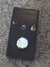
I built my own circuit to a small plastic box where I fitted the DC power connector, 6.3 mm output jack, switches and potentionmeter. The picture below is as taken from my protoype:
Circuit tuning
When you have the circuit ready and working then you have to set up the maximum frequency limit on this circuit. It is not advisable to use higher than 15 Hz strobo flash frequencies, so set R3 so that the maximum output frequency of the circuit is 15 Hz. When you have doen the tuning then it is best to fix the potentiometer to it's place for example using glue so that the settings does not change because of vibrations and shocks this controller might need to face.
Powering the circuit
Best way to power this circuit is to use a small wallwart. The circuit needs less than 100 mA of current, so a small 12V wallwart is ideal for this circuit. If you plan to use a batteries to power this circuit then you should also add a power switch to the circuit.
Modification ideas
If you want to see the frequency the controller sends out before actually firing the strobocope, you can add another LED to the circuit which flashes continuously at the oscillator output rate. You can add that extra LED in the following way:
- Wire LED and 470 ohm resistor in resies in the same way as R4 and D4 are wired.
- Connect the LED to ground as D4 is connected.
- Connect the free end of the resistor in your circuit to the pin 3 of U1.
Tomi Engdahl <[email protected]>