


Telephone line audio interface circuits
Copyright 1996-2001 Tomi Engdahl
First of all, I must officially advise against connecting anything other to the telephone line than equipment approved for the purpose by the telephone company or some other regulatery body. Telephone company tend to be very strict about unauthorized gear hanging on their lines, and if something does go wrong with your gadget (like putting dangerous voltages to telephone line) you will be in deep trouble.
Index
- How telephone works
- Network Interface in telephone
- Telecom hybrid circuits for other equipments than telephones
- Audio interfaces to telephone lines
- Telephone audio interfaces from Usenet news
- Audio interfaces without transformer isolation
- Simple telecom hybrid circuits
- More details implementing telephone line interface
- Problems in linking telephone hybrid to audio system
- Helpful tips for telephone hybrid circuit designers
- Connecting hybrids and telephone equipments
- Components for telephone line interfacing
- Telephone line technical details
- Telephone line details in different countries
- Interference in the telephone line signal
- Other related document
- Final words
How telephone works
A telephone uses an electric current to convey sound information from your home to that of a friend. When the two of you are talking on the telephone, the telephone company is sending a steady electric current through your telephones. The two telephones, yours and that of your friend, are sharing this steady current. But as you talk into your telephone's microphone, the current that your telephone draws from the telephone company fluctuates up and down. These fluctuations are directly related to the air pressure fluctuations that are the sound of your voice at the microphone.
Because the telephones are sharing the total current, any change in the current through your telephone causes a change in the current through your friend's telephone. Thus as you talk, the current through your friend's telephone fluctuates. A speaker in that telephone responds to these current fluctuations by compressing and rarefying the air. The resulting air pressure fluctuations reproduces the sound of your voice. Although the nature of telephones and the circuits connecting them have changed radically in the past few decades, the telephone system still functions in a manner that at least simulates this behavior.
The current which powers your telephone is generated from the 48V
battery in the central office. The 48V voltage is sent to the telephone
line through some resistors and indictors (typically there is 2000 to 4000 ohms in series with
the 48V power source). The old ordinary offices had about 400 ohm line
relay coils in series with the line. Here is a simplified
picture of typical traditional telephone line interface:
to
Telephone central                              Telephone equipment

Ground -----+
            |                          Hookswitch  /
          COIL 5H                             +--o/ o-------+
            |                                 |             )|| ___
          Resistor 200 ohm                    |         ____)||(   |
      2uF   |                            TIP  |        |    )||( Speaker
    --||----+--o---------------------------o--+       Mic   )||(___|
Audio               Line wire                          |    )||
    --||----+--o---------------------------o-----------+----+
      2uF   |                            RING
          Resistor 200 ohm
            |
          COIL 5H
            |
-48V DC ----+
In some old switches there rere no separate reistors after the relay couils. Just a relay with 2x500 ohm coils was uased for both current limiting and the coils between the line wires and the power source.
When your telephone is in on-hook state the "TIP" is at about 0v, while "RING" is about -48v with respect to earth ground. When you go off hook, and current is drawn, TIP goes negative and RING goes positive (I mean less negative). A typical off hook condition is TIP at about -20v and ring at about -28v. This means that there is about 8V voltage between the wires going to telephone in normal operation condition. The DC-resistance of typical telephone equipment is in 200-300 ohm range and current flowing through the telephone is in 20-50 mA range.
Why 48V voltage is used in telephone systems ?
The -48V voltage was selected because it was enough to get through kilometers of thin telephone wire and still low enough to be safe (electrical safety regulations in many countries consider DC voltages lower than 50V to be safe low voltage circuits). 48V voltage is also easy to generate from normal lead acid batteries (4 x 12V car battery in series). Batteries are needed in telephone central to make sure that it operates also when mains voltage is cut and they also give very stable output voltage which is needed for reliable operation of all the circuit in the central office. Typically the CO actually runs off of the battery chargers with the batteries in parallel getting a floating charge.
The line feeding voltage was selected to be negative to make the electrochemical reactions on the wet telephone wiring to be less harmful. When the wires are at negative potential compared to the ground the metal ions go form the ground to the wire instead of the situation where positive voltage would cause metal from the wire to leave which causes quick corrosion.
Some countries use other voltages in typically 36V to 60V range. PBXes may use as low as 24 Volts and can possibly use positive feeding voltage instead of the negative one used in normal telephone network. Positive voltage is more commonly used in many electronics circuits, so it is easier to generate and electrolysis in telecommunications wiring is not a problem in typical environment inside office buildings.
Some older offices employ battery reversal (swap DC feed to tip and ring) to signal off-hook at the remote end.
What is sealing current ?
The current sent to telephone line as an another advantage besides that it supplies the operating power for your telephone. Telephone practice uses (or did use) twisted splices. These splices did not always make good connections. Placing a small DC bias on a long transmission pair is often done by telecommuncation carriers to reduce poor connections, and noisy lines. The DC bias is often refered to as a "sealing current". So putting DC current through the cable sealed the connection and so improved the transmission.
Why full duplex operation in single wire pair ?
Full-Duplex is a term used to describe a communications channel which is capable of both receiving and sending information simultaneously.
Telephone sets (ordinary analog ones) have only 2 wires, which carry both speaker and microphone signals. The signal path between two telephones, involving a call other than a local one, requires amplification using a 4-wire circuit. The cost and cabling required ruled out the idea of running a 4-wire circuit out to the subscribers' premises from the local exchange and an alternative solution had to be found. Hence, the 4-wire trunk circuits were converted to 2-wire local cabling, using a device called a "hybrid".
This function can send and receive audio signals at the same time is accomplished by designing the system so that there is a well balanced circuit in both ends of the wire which are capable or separating incoming audio from outgoing signal. This function is done by telephone hybrid circuit contained in the network interface of the telephone.
What is the bandwidth of the telephone line ?
A POTS line (in the US and Europe) has a bandwidth of 3kHz. A normal POTS line can transfer the frequencies between 400 Hz and 3.4 Khz. The frequency response is limited by the telephone transmission system (the actual wire from central office to your wall can usually do much more).
Nowadays POTS is sharply bandlimited due to the fact that the line almost always is digitally sampled at 8kHz at some point in the circuit. The absolute, theoretical limit (with perfect filters) is therefore 4kHz - but this isn't reality, 3.4 kHz maximum frequency is.
The bass frequency response is limted because of the limitations in telephone system components: transfromers and capacitors can be smaller if they don't have to deal with lowest frequencies. Other reason to drop out the lowest frequencies is to keep the possibly strong mains frequency (50 or 60 Hz and it's harmonics) hummign away from the audio signal you will hear.
Network interface details
The telephone has a circuit called network interface (also called voice network or telephone hybrid) which connects the microphone and speaker to the telephone line. Network interface circuitry is designed so that it sends only the current changes the other telephone causes to the speaker. The current changes which the telephone's own microphone generates are not send to the speaker. All this is accomplished using quite ingenious transformer circuitry. In theory the hybrid circuit can separate all incoming oudion from the audio sent out at the same time if all the impedances in the circuitry (hybrids on both ends and the wire impedance in between) are well matched. Unfortunately, the hybrid is by its very nature a "leaky" device. As voice signals pass from the 4-wire to the 2-wire portion of the network, the higher energy level in the 4-wire section is also reflected back on itself, creating the echoed speech. The because circuit does not work perfectly and you can still hear some of your own voice in the speaker
The actual amount of signal which is reflected back depends on how well the balance circuit of the hybrid matches the 2-wire line. In the vast majority of cases, the match is quite poor, resulting in a considerable level of signal being reflected back.
The signal which is reflected back is not always bad and in normal telephone some if it is really intentional by the design. The separation of the received and transmitted audio could be done much better with modern electronics than with old phones, but but people who use the telephone prefer to hear some of their own voice back. Radio Shack's "Understanding Telephone Electronics" (copyrighted around 1985 I think) calls this effect sidetone and gives the impression that this was indeed intentional in order for the speaker to determine how loud they were speaking with reference to the called party.
Signaling
Ringing signals
When the central office want to make your telephone ring it will send an AC ringing voltage to the line which will ring the bell in your telephone. Most of the world uses frequencies in 20..40 Hz range and voltage in 40..150 volts range.
The ringer is built so that it will no pass any DC current when it is connected to telephone line (traditionally there has been a capacitor in series with the bell coil). So only the AC ring singal can go though the bell and make it ring. The bell circuit is either designed so that it has high impedance in audio frequencies or it is disconnected from line when phone is picked off-hook.
For more information about telephone ringing take a look at my telephone ringing circuits web page.
Dialing
There are two types of dials in use around the world: pulse dialing and tone dialling.
The most common one is called pulse dialing (also called loop disconnect or rotary dialing). Pulse dialling is oldest form of dialing, it's been with us since the 1920's. Pulse dialing is traditionally accomplished with a rotary dial, which is a speed governed wheel with a cam that opens and closes a switch in series with your phone and the line. It works by actually disconnecting or "hanging up" the telephone at specific intervals. The mostly used standard is one disconnect per digit (so if you dial a "1," your telephone is "disconnected" once and if you dial "2" your telephone is "disconnected" twice and for zero the line is "disconnected" ten times) but there are also other systems used in some countries.
Tone dialing is more modern dialing method is usually called with names Touch-tone, Dual Tone Multi-Frequency (DTMF) or Multi-Frequency (MF) in Europe. Touch tone is fast and less prone to error than pulse dialing. Bell Labs developed DTMF in order to have a dialing system that could travel across microwave links and work rapidly with computer controlled exchanges. Touch-tone can therefore send signals around the world via the telephone lines, and can be used to control phone answering machines and computers (this is used in many automatic telephone services which you operate using your telephone keypad). Each transmitted digit consists of two separate audio tones that are mixed together (the four vertical columns on the keypad are known as the high group and the four horizontal rows as the low group). Standard DTMF dials will produce a tone as long as a key is depressed. No matter how long you press, the tone will be decoded as the appropriate digit. The shortest duration in which a digit can be sent and decoded is about 100 milliseconds (ms).
Other signals
The telephone central can send any different types of signals to the caller telling the status of telephone call. Those signals are typically audio tones generated by the central office. Typical this kind of tones are dialing tone (typically constant tone of around 400 Hz), calling tone (tone telling that the telephone in other end is ringing) or busy tone (usually like quickly on and off switched dialing tone). The exact tones used vary from country to country.
Detecting end of call
There is no guaranteed (single) way to determine when a call was terminated at the far end. Depending on the switch type you need to look at loop break (loss of loop current), change of DC polarity, dial tone, stutter dial tone, and/or silence. If you want to do something for unknown lines on unknown switches then you will need a combination of the above.
Safety issues of telephones
The telephones should be designed so that they do not cause danger to the user. The 48V DC voltage in telephone lines does not cause immediate danger to the user, but the AC ring signal (70-120V AC) can give a nasty shock. Telephone wires are also exposed to any different environmental effects (nearby lightning, ground potential differences in buildings, interference from power lines) which can cause that there are sometimes high voltage spikes on the telephone wires. Normal telephones are designed to be fully enclosed in insulating plastic case which provides isolation. The plastic case works nicely as isolation if there are no metal contacts in the telephone which are somehow connected to telephone line.
If the equipment has touchable metal surfaces or connections for power from other sources the equipment must provide proper electrical isolation between the telephone line. You have to provide 1500 volts between the telephone line and rest of your electronics. Typically computer modems does this isolation using transformers, optoisolators and relays.
The telephone company can't know what kind of foolishly designed gadgets their customer has hanging on the end of line, but it does specifically tell them, that at any time without warning and at their convenience they might just put a variety of voltages and currents on any given loop. If the device is not designed to meet the regulations it can cause dangers or problems in those situations. Equipments must be also designed to meet the safety rules so that they do not led dangerous voltages to enter telephone lines and causing a danger of being electrocuted to the telephone company workerd which do the wiring.
DO NOT PUT, in series or in parallel, into a telephone local loop:
- Batteries of any kind
- Polarized capacitors
- Diodes of any kind
- 1/4 watt resistors (or any other 10 cent resistor!)
- Lamps
The simple things are that the telephone line is a balanced transmission line which can have up to 120 ma of DC current from up to 56 VDC (actually in some cases up to 90 VDC) and up to 120 VAC RMS (ring voltage) in the way of various voltages and currents. Those voltages and currents can be any polarity and might be applied all at one time.
Telephone line parameters
Telephone line resistance, capacitance and inductance do not depend on the voltage or current on the line.
Line balance
For telephone local loops, crosstalk is related to how well balanced the circuit is. Loop current does not affect that balance, even if excessively high. If the balance is not gooe enought you can hear crosstalk form pther telephone lines or from other noise sources. The balance of the telephone line is determined by the circuits connected to telephone line ends (typically line transformers) and the quality of the telephone cable (wet cable can cause noticable balance problems if wires are in contact with the water).
Loop current effects
The detrimental effects of excessive loop current would be distortion caused by saturation of transformers ("repeat coils" in the vernacular). Within the range of acceptable loop current (up to 120mA), no transformer used in a telephone equipment should become saturated. If an inferior transformer is used, or if loop current were significantly higher than 120mA, then distortion could be expected. Neither situation is common.
Network Interface in telephone
The telephone has a circuit called network interface (also called voice network or telephone hybrid) which connects the microphone and speaker to the telephone line. Network interface circuitry is designed so that it sends only the current changes the other telephone causes to the speaker. The current changes which the telephone's own microphone generates are not send to the speaker. All this is accomplished using quite ingenious transformer circuitry. The circuit does not work perfectly and you can still hear some of your own voice in the speaker (it could be done better nowadays but people who use the telephone prefer to hear some of their own voice back).
Simplified traditional network interface
Normal telephone consist of ringer, dialing circuit and voice circuit. A traditional telephone voice circuit consisted of hybrid transformer, speaker, carbon microphone and one resistor.
                 Hookswitch
                    /             Transformer
   Tip   ---------o/  o------------+
                                   |
                                    ) ||
                                    ) ||  _____   _  /
                                    ) || (     |_| |/
                      ______________) || (      _| |   Speaker
                     |              ) || (_____| |_|\  (32-64 ohm)
                     |              ) ||             \
                  Carbon            ) ||
                  Microphone       |
                     |            | |
                     |            | | Resistor
                     |            |_|
                     |             |
   Ring -------------+-------------+
The circuit is designed so that the impedance at audio frequencies looks like about 600 ohms. The audio impedance is controlled by the transformer characteristics, carbon microphone, speaker impedance and the resistor in series with the transformer.
The DC resistance consist of the transformer coil in series with the resistor and part of the coil in series with carbon microphone. The carbon microphone is put to the transformer so that the changes in the current flowing through it do not generate voltage to the secondary coil where the speaker is connected.
Modern telephone circuit are much more complicated because they typically include compensation for the attenuation caused by long subscriber lines. This compensation is done so that the audio levels are controlled according the current flowing through the telephone (longer line has more resistance so there is less current which you get form 48V source through it).
Why carbon microphone in telephones ?
Carbon mikes were the first microphones and consisted of a small button of carbon powder connected to a metal diaphragm. When sound flexed the diaphragm, the carbon grains changed their electrical resistance. When a voltage source is applied between the microphone wires a variable current is generated. This is how the first telephones were constructed, and many phones to this day still use the idea. Carbon microphones have poor frequency response and bad signal-to-noise ratios and they are only suitable for telephones and such communication applications.
Typical European Network
The following network circuit schematic was shown in
BUILDING AND USING PHONE PATCHES by Julian Macassey:
      A  \
     o--o.\---------o----o----o-------|
         .          | 0.1|    |       |
         .          |  uF|    |       |
         .          |   ---   \       |
         .          |   ---   / 1k    |
         .          |    |    \       |
         .          |    |    |       |
         .          |    -----o----)|||
         .          |              )|||
     S1  .          |              )||o------o-----
    HKSW .          |         200  )|||   VR |    |
         .       TX O          Ohms)|||   60 |    |
         .          |              )||(    -----  |
         .          |              )||(     ^ ^   O RX
         .          ---------------|||(    -----  |
         .                     50  )||(60    |    |
         .                     Ohms)||(Ohms  |    |
      B \.                         )||(------o-----
     o--o\-------------------------)||
Note: I have edited the schematic by replacing the component numbers
with the component values listed in component list.
Simplified U.S. Standard "425B"
This circuit is put here to show an example of the electronics inside typical traditional telephone which uses hybrid transformer circuit. Modern telephones usually have special ICs to do the same things without the transformer. The circuit tries just to be an example what's on inside typical old telephone for those who want to know how telephone works. Building this circuit is not a good idea because the circuit diagrams does not have all component values and the circuit is optimized only for telephones (it is not good for anything else).
This circuit is taken from
UNDERSTANDING TELEPHONES
article by Julian Macassey.
Component values may vary between manufacturers.
The circuit is designed to operate with
standard telephone speaker (RX) and carbon microphone (TX).
Connections for Dials, Ringers etc. not shown to keep the picture
a little bit clearer.
                         +-------------------+
                       ..|...................|
                       . |                  .|
     Sidetone balancing. |  0.047uF 250V    .|
     impedance & loop  . |    | |           .|
     compensation. >>> . o----| |-------o   .|
                       . |    | |       |   .|
                       . |              |   .|
                       . |    |<| VR2   |   .|
                       . o----| |-------o---.|
                       . |    |>|          |.|
                       . |                 |.|
                       . |   68 Ohms       |.|
                       . o---\/\/\/-----|  |.|
                       ..|..............|..|.|
                         |              |  | |
                         |        .     |  | |
                         +----)||(------|---------o (GN) --+
                             1)||(5     |  | |             |
               Loop           )||(      |  | |             |
     TIP       Compensation  2)||(6     |  | |             |
  L1 o------ \------o---------)||(------o  | |          RX O  Speaker
            .       | (RR)   . ||       |  | |             |
            .       |          || 1.5uF |  | |             |
            .       \ 180      ||      --- | |             |
            .       / Ohms     ||      --- | +----o (R) ---+
            .       \          || 250V  |  |               |
            .       |          ||       |  |               |
            .  VR1 ---       . || .     |  |               |
            .      ^ ^    ----)||(------o--+            TX O  Microphone
            .      ---    |  3)||(7                        |
            .       |     |   )||(                         |
     RING   .       | (C) |  4)||(8       22 Ohms          |
  L2 o----- \-------o---------)||(---o----/\/\/---o (B) ---+
                          |          |
            ^             |          |
        Hookswitch        +----------+
The circuit is quite complicated because it is optimized for use
in standard telephone which is used in various conditions.
Varistors VR1 and VR2 are used for loop compensation
circuit which tries to keep the telephone volumes
(incoming and outgoing) at suitable levels even if the
local loop attenuation varies. This compensation can be done
because longer local loop which has more attenuation
has also more resistance, so less current passes through
the telephone. If the loop is very short there is more
current passing through the telephone and the varistors
cause more signal attenuation inside the telephone hybrid.
The hybrid circuits in telephone sets are deliberately mismatched, so that you can hear yourself in the earpiece when you speak. This is called "sidetone".
Details of wiring inside telephones used in USA
The following wiring info is from wiring.inside.phones document from TELECOM Digest Archive
This should apply to all WE phones and ITT phones that use the standard dial/ringer/network block/ handset configuration. Everything basically talks to the network block. The network block contains the ringer capacitor, the induction coil that handles the handset, and very little else save some spare screw terminals. The network block can function as a standard line load [it looks electrically like a phone] when a line is connected across RR and C (These are the inputs to the coil). The ringing capacitor is across A and K contacts.
Handset connections: Green and White are earpiece leads which connect to R and GN respectively. Black and Red are mike leads and they connect to B and R respectively.
Ringer: Connect the single winding in series with the A-K capacitor and this whole thing across the line.
Rotary dial: Blue and Green go to interruptor (net F and RR)
Touch-tone dial: Green is + line in and connects to net F. Black is + line out and connects to net RR. Org/Blk is - line in and connects to net C. Red/Grn is output common and connects to net R. Blue is signal output and connects to net B.
Hookswitch: You'll find many variants of this in different units; some configurations switch both sides of the line, some only one, some switch out the ringer when off-hook. One switch switches the connection between L2 and C. Another switch switches the connection between L1 and RR.
Line in: Green and Red connect to L1 and L2. Try one polarity; if the touchtone dial doesn't work, then flip them.
Telecom hybrid circuits for other equipments than telephones
Traditional transformer hybrid circuit
The transformer type was the most used to make telephone hybrids (around 1964 or so) was four winding transformer. Two of those were needed for one hybrid circuit.
Richard Harrison gave me the follwong description how to make such hybrid circuit: To make the hybrid, strap two coils together in each transformer (series-aiding in each case). Call them primaries. One primary will serve as the 4-wire transmit connection. The other primary will serve as the 4-wire receive connection. Four coils, two on each transformer remain undedicated at this point. Connect the start terminal of a secondary coil on one transformer to the finish terminal of a like coil on the other transformer. The other two terminals of this pair of secondary coils will be dedicated to a balancing network.
Two coils now have no connections, yet. Connect the start terminal of the coil on one transformer to the start terminal of the coil on the other transformer. The other two terminals of this pair of secondary coils will be dedicated to the 2-wire line.
Because there is a polarity reversal in the interconnection in one of the two paths between the two transformers, no coupling will exist between the transmit and receive connections of the 4-wire paths (provided perfect balance in the line-balance network against the 2-wire line). The 2-wire line will,however, be coupled with the transmit and receive pairs of the 4-wire line. That is what the hybrid is supposed to do.

The advantages of the traditional circuit are, high isolation. No dc path exists between any lines. The circuit is completely passive and precision balance can produce almost any desired transhybrid loss. You should get very good results when you implement this circuit using high quality audio transformers (for example broadcast quality Western Electric 111-C "repeat coils", Lundahl Transformers Hybrid Transformers etc.).
Siemens and ITT resistive hybrids
This is a simplified circuit diagram you can made a simple 600 ohm hybrid as such.
The circuit is indeed a Wheatstone bridge consisting of four 620 ohm
impedances (one of them is telephone line in series with 2 uF DC blocking capacitor).
Phone line                                        Transmit      Receive

----------------------------------|-------------------S1
line input/LA)                   620 ohm
                                  |-------------------------------R1
                                 620 ohm
                                  |-------------------S2
Line input/LB                    620 ohm
----------------------2uF---------|-------------------------------R2
Receiver connected to R1/R2 and transmitter is connected to S1/S2. Note that this circuit does not show any dc paths which would be needed for real telephone line hybrid. Loss on all ports are 6dB nominal. This hybrid design can be used for simple experimenting when measuring telephone equipments and such applications.
Better hybrids with two transformers have a typical loss of 3,5dB and 30dB isolation from TX to RX (but typically little isolation from RX to TX but that does not typically matter).
One transformer hybrid circuit for 2 wire to 4 wire conversion
This is a quite typical 4 wire to 2 wire conversion circuit which is shown in telecom books.
LINE 2W ----------------------/ II /------------- RX 4W
                              / II /
                              / II /
                              / II /
                              / II /
          TX 4W --------------/ II /            Receive
          Transmit            / II /
          TX 4W --+           / II /
                  |           / II /
                  |           / II /
LINE 2W ----------+-ZZZZ------/ II /------------- RX 4W
Here the wires marked with LINE 2W are the wires of the 2 wire duplex line. Wires marked with RX and TX belong to 4 wire line. RX is the pair where the received audio form 2 wire line comes. TX is the pair where the audio which is to be transmitted to 2 wire line are sent. The component market with ZZZZ models the telephone line impedance (typically around 600 ohms).
Notes about telephone transformers
Telephone line inmterfacing transformers are usually called 600:600 ohm transformers (or 1:1 ratio 600 ohm transfromers). The both markings tell that the transformer has (around) same number of turns on both primary and secondary coils and they are optimized to operate at 600 ohm load. The 600 ohm load does not tell the primary or secondary coil resistances or impedance, it just tells in what kind of application the transformer is designed to be used. The DC resistance of typical telephone line transformer coils is around in 40-150 ohm range and inductance is typically in range of few henries.
A 600:600 transformer is optimised for 600 ohms use, but of course will work over a range of impedances more or less well (for example you lose a whole octave at the low frequency end if the impedance is 1200 ohms).
Telephone line interfacing transformers are available in two major types "wet" and "dry". Typical modern transformers are "dry" type, because they perform well and anre small, but can'twithstand the line DC current going though them without saturation. "Dry" transformer can be used in application where line current is blocked not to go though the line transformer and if some current must be taken from the line, an alternate path is provided for it.
"Wet" transformers are are designed so that they can withstand the DC current present on the telephone line flowing though their primary without transformer saturation. Ther drawback of "wet" transformers are that they are typically bigger and have worse performance figures than "dry" transformers. "Wet" transformers are traditionally used in telephoine circuit, but nowadays they are more and more often relaced with "dry" transformers for economical and technical reasons (a high speed modem would not work well if it would use typical "wet" telephone transformer). The "wet" transformers have typically the maximum allowed direct current listed on their datasheet (more current than that will saturate the transformer core).
Telephone line transformers provide also isolation from the telephone line. Normally the voltages on telephone line are in order of 100V, but in some special cases there can be higher voltages present on the telephone line or between the equipment and telephone linne, so the transformer must withstand quite high voltages to be safe in such circuimtances. Typical telephone transformers are rated to have the isolation rating of around 1000-4000V range (look for the transformer datasheet and your local safety regulations to selector a type which has high enough isolation voltage rating).
Audio interfaces to telephone lines
The following two interfaces were designed for connecting small tape recording to telephone line for recording telephone conversations. The interfaces are connected in parallel with the telephone and they can be kept connected to telephone line all the time because they only pass the audio signal, not the DC which is used in telephone system to detect when phone is picked up. The original Philips and Norelco interfaces are type approved for use in Finland for connecting telephone line to tape recorder.
Those two circuits are useful because they don't pick up the line when they are inserted to telephone line and they pass the audio even when the line is not picked up. That makes then useful fo connecting computer sound cards and caller ID circuit to telephone line. If you worry about spikes coming from telephone line your circuits, you can use pair of diodes or zener diodes to limit the spikes on the transformer secondary.
If you can find this kind of interfacing circuit approved and ready-made, it would be safe to use ready-made interface. In this you don't have to worry about getting into problem from connecting non-approved circuits to telephone line. If you happen to live in USA you can use Xecom XE0068 Data Access Arrangement module which provides legal and quite low cost interface to the phone system with FCC Part 68 registration (the registration transfers to final product which uses this module). Xecom makes also similar DAA modules to meet the regulations in use in other countries also. CP Clare advertises quite actively it's CYBERGATE Telephone Line Interface DAA Modules in their web pages and some electronics design magazines.
Philips recording interface
The first circuit is Philips LFH0117/00 telephone recording adapter, which is not manufactured anymore I think. The circuit is quite typical telephone recording adapter design. I have used succesfully for getting audio from telephone line to soundcard and my stereo system.
The circuit is designed to be connected in parallel with normal telephone. This circuit does not provide any DC path or correct impedance matching to telephone line because the telephone provides them (this circuit is designed so that it disturbs the operation of telephone as little as possible so it has high impedance input).
I found out the type of all other components than the transformer T1. T1 is the audio isolation transformer, which seems to have properties quite similar to typical 600:600 ohm telecom isolation transformer. The components F1 and F2 are 50mA fuses. The signal output level is suitable for microphone input because the resistors attenuate the voice signals form telephone line around 40 dB (some telephone equipment regulations in Finland needed this). On the picture below you can see a picture of the inside of the Philips LFH0117/00 telephone recording adapter:
In the circuit the two 15nF capacitors are blocking the line DC level and the low frequency for ringing. All other compnents are safety requirements, for lowering the noise and for matching the telephone equipment regulations (signal isolation from line, impedances etc.). This schematic is basically a very safe one: fuses are not necessary for proper function (just for extra safety) and the transformer provides galvanic isolation from telephone line. The circuit is designed to be connected to the microphone input of a recorder (the output signal level is typically few millivolts which is too low for any other type of input).
Norelco recording interface
The second circuit is made by Norelco and is also designed to be used in parallel with existing telephone. This circuit has much less attenuation between telephone line and tape plug so you get stronger output signal out. I have used this circuit successfully for getting some audio from telephone line and sending some audio back to telephone line.
I found out the type of all other components than the transformer T1. T1 is the audio isolation transformer, which seems to have properties quite similar to typical 600:600 ohm telecommunications isolation transformer. The components F1 and F2 are 50mA fuses.
Recording interface from Tekniikan Maailma magazine
The third circuit was shown in an article written by Martti Koskinen in Tekniikan Maailma magazine issue 8/1994 pages 94-95. The circuit is designed for recording telephone conversations using normal tape recorder. The circuit has an option to also play back sound tot the telephone line from reparate connector. The transformer T1 is typical 600:600 ohm telephone isolation transformer with centre tapped secondary. This circuit is also designed to be used in parallel wiht existing telephone.
The capacitors C1 to C4 are connected in parallel to make about 200 nF capacitance. Four separate capacitors can be more easily fitted to one case than single 200 nF 250V capacitor which is quite large. I don't know the reason of why R1 and R2 are connected in parallel, because single 4.7 kohm resistor would do their job as well.
Marantz PMD recorder series
                    ||
   Tip   ---+-------||----+--------+
            |       ||    |        |      +----+----------+----- Audio ut
            |     470 nF  |        |  ||  |   _|_         |
            |             |         ) || (     \          |
            |             |         ) || (    /_\ zener   |
           | |           ---        ) || (     |         | |
           | | 470 ohm   --- 47 nF  ) || (    \ /        | | 4k7
           |_|  1/2W      |         ) || (    _\_ zener  |_|
            |             |        |  ||  |    |          |
            |             |        |      +----+----------+------ Audio ground
   Ring ----+-------------+--------+
Tip and ring are first shunted with a 470 ohm 1/2 W resistor (to allow the interface to sieze the line). Next, before the transformer primary, there is a 470nF series cap (high pass, and DC transformer isolation) and a 47nF shunt cap (low pass to limit the upper end). The transformer is a 1:1 600 ohm, I believe, though the schematic doesn't specify.
On the secondary there is first a shunt pair of back to back Zeners to limit the max voltage seen by the the recorder circuit, and then a shunt 4.7K ohm to ground.
Telephone audio interfaces from Usenet news
There have been presented many telephone interfacing circuits in Usenet newsgroups. Those circuit have been more or less good. Most of them works somehow, but fail to meet the technical specs needed from telephone circuits. More or less they have usually been very simple circuits
Simple audio interface
Jim Earl ([email protected]) has shown out very simple circuit for
connecting telephone signal to SSI202 DTMF decoding chip audio input.
The circuit is basic 600:600 ohm transformer isolation circuit with capacitor
in series with primary circuit and potentiometer for setting
the output signal level. The circuit us designed to be used in parallel
with existing telephone or other telecom equipments.
                    .22 uf              10k pot
                     400v    ||(----------->
Phone line tip  o-----)(----)||(           <---o to SSI202 input
                            )||(           >
Phone line ring o-----------)||(-----------o---o ground
This circuit works as designed with the chip specified, because it has high impedance input. The design has one problem: If this circuit is connected to low impedance input and the output potentiometer is set to maximum level, the low impedance is reflected to primary side of the transformer, which is not good.
My recommendation is to change the capacitor size to to 0.1 uF and
add one 4.7 kohm resistor in series with circuit input or output.
That will keep the circuit from disturbing the telephone line when
connected to other circuits.
                    .22 uf              10k pot
                     400v    ||(----------->
Phone line tip  o-----)(----)||(           <---o to SSI202 input
                            )||(           >
Phone line ring o---\/\/\/--)||(-----------o---o ground
                     4k7
Telephone to studio mixer interface
The second circuit from news is designed by [email protected]. The circuit seems to be quite nice desing and should work nice with mixers which have imput impedance of 600 ohm (mic input) or higher. The transformer and 44 nF capacitor keeps the impedance seen from line high enough that not bad mismatching happens when connected to studio mixer. If I would be connecting something like this to my audio gear I would add some type of surge protection to the circuit (two zener diodes in output would be nice) or add external surge protector. But let's the original text to describe the circuit in more detail.
We use telephone audio in our studio all the time. And yes, it's an off
the shelf design. I designed and built such a device with scrap door
components. I used an audio coupling transformer and a capacitor.
The primary windings add in series to 500 ohms. Instead of connecting
them directly together I added a cap between them. I it was something
like 0.047 micro farads with a 600 volt rating. And the secondary
which is 500 ohms runs into the control room mixer.
           Tip   >------------/ II
                              / II /------------<
      (primary winding 1)     / II /
                              / II /
                 >-----X------/ II /
                       I        II /
         0.047 uF      =        II / -----------CT   (secondary winding)
                       I        II /
                >------X------/ II /                      Output Side
                              / II /                        to Mixer
      (primary winding 2)     / II /
                              / II /-------------<
        Ring    >-------------/ II
Try this circuit it works great for us in the studio.
The circuit is designed to be used in paprallel with existing telephone.
Just make sure you use properly rated components.
Other transformer isolated interfaces
I saw the following circuit idea Bowden's Hobby Circuits site and make my own modification of the circuit.
A non-polarized capacitor is placed in series with the transformer line connection to prevent DC current from flowing in the transformer winding which may prevent the line from returning to the on-hook state. The capacitor should have a voltage rating above the peak ring voltage plus the on-hook voltage (typically 138V total), so a 400V capacitor is recommended.
Audio level from the transformer is about 100 millivolts which can be connected to a high impedance amplifier or tape recorder input. The 620 ohm resistor serves to reduce loading of the line if the output is connected to a very low impedance.
For overvoltage protection, two diodes are connected across the transformer secondary to limit the audio signal to 700 millivolts peak during the ringing signal.
Audio interfaces without transformer isolation
In some special case the audio interface is built without isolation transformers. In those cases the audio signal is passed from telephone line through the capacitor which blocks the DC from telephone line. This type of isolation works quite well in applications where you don't want to use the transformer but you still want to get some audio from the line. Typical application is called ID boxes.
A typical capacitor isolation circuit:
                         C1  R1
           Line ---------||-/\/\--o------O
                                  |
                                  \
                               R3 /       Audio out
                                  \
                         C2  R2   |
           Line ---------||-/\/\--o------O
The capacitors C1 and C2 will block the DC and pass the audio
signal to the output. The resistors R1 and R2 provide some protection
against the spikes on the telephone line and make sure that the circuit
is so high impedance that it does not disturb the telephone line operation.
R1, R2 and R3 make together a voltage division network which will
attenuate the audio signal coming from telephone line to the desired
signal output level.
The circuit should be connected to differential audio input. If the circuit is connected to single-ended input the circuit works worse and gets easily all kinds of interference. Capacitors C1 and C2 should be rated to handle the 1.5 kV pulses. The capacitors C1, C2, R1 and R2 should provide so high impedance to the telephone line that the telephone line balancing is not disturbed. You should also note that this circuit does not provide as good surge protection as transformer (surges can quite easily pass trough C1, C2, R1 and R2). This is not the preferred way to do the telephone line interface ! Preferred way is to use transformer isolation instead.
Example circuits
DTMF decoder schematic shown at http://www.ee.washington.edu/conselec/A95/projects/jjblome/links.htm used the following component values:
C1,C2    470 pF
R1,R2    10 kohm
R3       Not used
The output of the circuit was directly connected to the MC145447 IC differential audio input. The circuit isself was designed to be fitted inside an isolating plastic enclosure.
Caller ID detector schematic shown at http://www.helsinki.fi/~metsala/cid.txt used the following values:
C1, C2   10 nF
R1, R2   100 kohm
R3       (around 40 kohm)
The output of this circuit was directly fed to the differential input of MT8870C-1 DTMF decoder IC. The decoder IC was connected to the computer. In this applications is essential that the capacitors C1 and C2 can withstand the 1.5 kV surges which can be sometimes present in telephone line.
Simple telecom hybrid circuits
Telephone hybrid circuit is the circuit which is designed for converting 2-wire interface to 4-wire interface and is one of the basic building blocks of the telephone system. Telephone hybrid is the circuit which separates the transmitted and received audio which are sent both at the same wire pair in 2-wire normal telephone interface.
There are many different types of hybrid circuit in use. Traditionally telephones have used combination of special transformer and few additional components to keep incoming and outgoing signal separated from each other. Nowadays this is done more or less electronically.
In telephone central end hybrid circuits are needed when must be done any amplification to the signal. Traditionally the systems separate the incoming and outgoing signal, then they are amplified separately and sent to other telephone central using separate wires or otherwise separate communication channels. The oldest models of those circuits have been built from one or two transformers and some other balancing components to get best results. The problem have been how to get good balance to the hybrid circuit, said in other way how to separate incoming and outgoing signals as well as possible. Nowadays everybody is avoiding bulky and expensive special transformers and more and more electronics is used because it is cheaper. Modern hybrid circuits consists only of one audio isolation transformer, two operational amplifiers, resistors and some capacitors. and the most modern approaches try to avoid that transformer altogether by using active electronics circuits in telephone line side to do the job and optocouplers to do the isolation where needed.
Many different system circuit have been used and I am showing here just one basic transformer based circuit which easy to understand and is useful for many experiments.
       Primary 600 ohm                 Secondary 600ohm+600 ohm

           Tip   >------------/ II /------------< audio to telephone line
                              / II /              (low impedance output)
                              / II /
                              / II /
                              / II /
                              / II /------600ohm--Ground
                              / II /
                              / II /
                              / II /
                              / II /
         Ring   >-------------/ II /-------------> audio to mixer
                                                   (high impedance input)
This first circuit is a traditional simple hybrid circuit which have been
earlier successfully used in many telephone circuit (for example modems).
The circuit works so that the 600 ohm resistor in the center pin of the
secondary is seen as 600 ohm impedance load in primary circuit.
The end of the secondary which is connected to low impedance audio output
(for example amplifier made for driving small speaker) must be always
connected to amplifier or ground to make the circuit work as expected.
The audio signal output from the circuit must be fed to high impedance
(>10 kohm) audio input to make sure that the operation of the circuit is
not disturbed.
The circuit gives quite acceptable separation between incoming and outgoing signals when all impedances are set correctly. The 600 ohm impedance is kind of idealistic value and does not fully reflect the reality. In real life the impedance of the telephone line or telephone is not exactly 600 ohm and the transformer has it's losses. A 600 ohm resistor is anyway quite a good starting point.
If transmitted and received signals mix with each other, you will have to fiddle with the balancing network. For experiments I can suggest fitting 1 kohm variable resistor to the pace of 600 ohm resistor for experimenting which impedance value gives the best results. You may also want to try other type of line impedance simulation circuits if you know what what matches your system better. If the impedances presented by both the send and receive sides are the same the hybrid circuit will work quite well. You will find that the send and receive signals don't interfere with each other, but both come and go from and to the line.
If you are thinking of connecting this circuit to telephone line or otherwise sending DC current through the primary of the transformer remember to use a transformer which can handle the DC without saturating (telephone transformers made for "wet" circuits). And remember that there are strict rules what the equipment you connect to telephone line must meet and you are not allowed to connect anything not approved to public telephone system.
Modified circuit
The following circuit is for telephone line interfacing when using a 600 ohm to 600 ohm transformer with center tapped output:
       Primary 600 ohm                 Secondary 600ohm centre-tapped
                                       (same as 150ohm+150ohm secondary)

           Tip   >------------/ II /------------< audio to telephone line
                              / II /              (low impedance output)
                              / II /
                              / II /
                              / II /
                              / II /------150ohm--Ground
                              / II /
                              / II /
                              / II /
                              / II /
         Ring   >-------------/ II /-------------> audio to mixer
                                                   (high impedance input)
This circuit works the same as that circuit above, but uses standard
telephone line transformers easily available. One common transformer type
has 600 ohm primary and 600 ohm centre-tapped secondary. In centre-tapped
secondary each secondary side presents 150 ohm impedance. By using
150 ohm resistor connected to secondary centre pin, the primary sees
600 ohm impedance. Experimenters can try for example 470 ohm variable
resistor instead of 150 ohm fixed resistor to test which value gives the
best results.
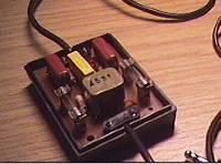
You can see this type of circuit built to a small plastic box at the picture below:
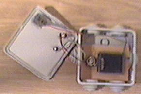
Soundcard to telephone line interface
The following circuit a a modifed version of the circuit above.
This circuit includes suitable audio output which can be fed to a
PC soundcard and a on/off hook switch:
       Primary 600 ohm                 Secondary 600ohm centre-tapped
                                       (same as 150ohm+150ohm secondary)
                /
      TIP ----o/ o------------/ II /------------< soundcard speker output
            ON/OFF HOOK       / II /
             SWITCH           / II /
                              / II /          +-< speker connector ground
                              / II /          |
                              / II /---150ohm-+
                              / II /          |
                              / II /          |
                              / II /          +-> line input connector ground
                              / II /
     RING --------------------/ II /------------> soundcard line level input
Remember that in telephony applications the signals levels must be adjusted carefully and sure must be made that the circuit is in good enough balance that there is no annoying feedback in the whole system. Warning that this cirucit is a little bit simplified interface diagram. This diagram lacks for example overvoltage protection on the audio output and also limiting circuits which stop too large signal levels to enter the telephone network.
Hybrid circuits for interfacing telephone equipments and not incoming line
Sometimes is is useful to connect telephone or a modem to hybrid
circuit instead of connecting hybrid circuit to telephone network.
This can be easily done by connecting the telephone/modem in series with
the primary of the hybrid circuit and then supplying well filtered
+12V power to that circuit to give power to the telephone in the
circuit and it is a good idea to feed the operating current to modem
also, because they are usually designed to operate when then line
current is present. The picture below tries to clear out the connection:
       Primary 600 ohm                 Secondary 600ohm centre-tapped
                                       (same as 150ohm+150ohm secondary)
              telephone
      +12V-------or-----------/ II /------------< audio to telephone line
                modem         / II /              (low impedance output)
                              / II /
                              / II /
                              / II /
                              / II /------150ohm--Ground
                              / II /
                              / II /
                              / II /
                              / II /
    GROUND--------------------/ II /-------------> audio to mixer
                                                   (high impedance input)
Telephone or modem and hybrid circuit provide the 600 ohm termination for each
other to operate correctly. The transformer used in hybrid circuit must be a
type which can handle at least 40 mA DC current without saturation.
It is a good idea to use 470 ohm trimmer in place of 150 ohm resistor
especially if you are trying to get the best performance with ordinary
telephone. In other way the circuits work in the same way as the hybrid
circuits above.
The possible uses for this circuits might be converting normal 2 wire modem
for operating in 4 wire circuit (for example for connecting to radio link)
or using normal telehone as microphone and speaker for computer soundcard when
doing Internet telephony. If you are planning to connect the circuit to
your soundcard use the following wiring:
       Primary 600 ohm                 Secondary 600ohm centre-tapped
                                       (same as 150ohm+150ohm secondary)
              telephone
    +9-12V-------or-----------/ II /------------< soundcard speker output
                modem         / II /
                              / II /
                              / II /          +-< speker connector ground
                              / II /          |
                              / II /---150ohm-+
                              / II /          |
                              / II /          |
                              / II /          +-> line input connector ground
                              / II /
    GROUND--------------------/ II /------------> soundcard line level input
Remember that in telephony applications the signals levels must be adjusted carefully and sure must be made that the circuit is in good enough balance that there is no annoying feedback in the whole system.
Operational amplifier based hybrid circuits
Modern modems use hybrid circuits built from operational amplifiers, resistors and one 600:600 ohm isolation transformer. With operational amplifier circuit the circuit can be made cheaper and performing better.
         Primary 600 ohm        Secondary 600ohm


                                   ____
    LINE --------------/ II /--+--|____|------+---< Audio to telephone line
                       / II /  |  600 ohm     |
                       / II /  |             | |
                       / II /  |             | | 600 ohm
                       / II /  |              |
                       / II /  +--> diff <----+
                       / II /  opamp circuit  |
                       / II /   for received | |
                       / II /      audio     | | 600 ohm *
                       / II /                 |
    LINE --------------/ II /-----------------+---- Ground
The source for audio signal which is transmitted to the telephone line should be low impedance to ensure that the impedance matching to telephone line is correct. For receiving audio a differential amplifier must be used to separate the incoming signal form outgoing signal, but differential amplifier is very easy to implement using operational amplifiers.
The performance of the circuit can be made better by replacing the 600 ohm resistor which is marked by * with some better model for the telephone line seen through the isolation amplifier. A better model provides better isolation between incoming and outgoing audio signals.
A quick note to mixing desk users: professional mixing desks nowadays have differential inputs and low impedance outputs. This makes it very easy to experiment with this type of circuit if you happen to own a good audio mixer.
Here is the full operational amplifier based hybrid circuit diagram
(theoretical circuit):
             |\  op amp buffer
   xmit------| >-------+-----------------+
             |/        |                 |
                       |                 |
                       \                 \
                       / R1              / R2
                       \                 \
                       /                 /
                 /|    |                 |
         op amp /-|----------------------+
   rcv-------- <  |    |                 |
                \+|----+                 |
                 \|    |                 | xfrmr
                       \            -->  )||(--------------  Tip
                       /            |    )||(                (to telco)
                       \ R3       (Rn)   )||(
                       /            |    )||(--------------  Ring
                       |            -->  |
                       |                 |
                      gnd               gnd
In the above diagram Rn = the telco network impedance as seen at the
other side of the transformer.
This circuit is an example of an "active" hybrid. Essentially it is a balanced network. If the ratio of Rl/R3 = R2/Rn, then you have infinite return loss - that is, you should have none of your transmit signal appearing on your receive line (when this happens, this signal is called side-tone). Yet the receive signal from the "far-end" will appear on the receive line. In other words, two signals can use the same two-wire interface, yet are seperable. Not theat the resistors which define the amplification of the opamps are not drawn here, so if you are plannign to build this circuit you will have to add them.
Unfortunately, telco line impedances can vary quite a bit, so the ratio of R2/Rn rarely equals R1/R3 except in situations where the designer has tight control over loop lengths and terminations. Any imbalance in the balanced network creates sidetone - a small amount of the transmit signal will appear on the receive line. In typical situations the sidetone can be attenuated aroun 20-30 dB with a well designed hybrid circuit.
Another typical way to implement a hybrid circuit is to build an optoamplifier circuit which takes the signal over the transformer coil and subtracts the transmitted signal from it. The following operational amplifier circuit does this:
The circut below is partly redrawn optimized hybrid circuit from National Semicondictor application note "Optimum Hybrid Design" from 1985 (that application note is no longer available).
The transformer in this circuit is 600:600 ohm telephone line transformer. For best results you have to adapt the component values slightly to match the line impedance and the transformer you are using.
That upper amplifier (the triangle with one input and output wire) is just a buffer amplifier with amplification factor of one. Signal from transmitter is connected to the positive input of opamp. The negative input of that opamp is conected to the opamp output.
More details implementing telephone line interface
Telephone line interface has to provide two functions when it is off-hook:
- Provide DC path for current flowing in telephone line. Normally there flows about 20-50 mA current in telephone line and telephone regulations typically sepcify that the DC resistance must be less than 400 ohms.
- Provide proper termination for telephone audio frequencies (300-3400 Hz). This is typically specified to be 600 ohms.
"Wet" transformer
Traditionally those two functions are accomplished in modems and their telephone interfaces are accomplished by "wet" telephone transformer. Wet type means that the transformer is designed to handle the DC current (typically 20-50 mA) properly and does not saturate at this DC current. Typically "wet" transformers are more expensive, bigger and have worse specs than "dry" transformers (which do not have to withstands any DC current). The proper termination in modems is provided by the electronic hybrid circuit connected to of the transformer. Another possibility is to use transformer which with center tap and build simple transformer and resistor hybrid circuit around it.
Here is a typical circuit for "wet transformer:
          Hookswitch
              /
   Tip   ---o/ o-------------------+
                                   |      +------->
                                   |  ||  |
                                    ) || (
                                    ) || (
                                    ) || (      To hybrid circuit which
                                    ) || (      prodived 600 ohm termination
                                    ) || (
                                   |  ||  |
                                   |      +------->
   Ring ---------------------------+
The circuit operation is quite straightforward. when the hookswitch is closed the telephone line DC current starts to flow trough the transformer primary coil. The DC resistance of the circuit is determined by the resistance of the transformer primary coil (typically in 60-200 ohm range in 600:600 ohm telecommunication transformers). The transformer is 1:1 transformer designed to operate at 600 ohm impedances, so 600 ohm termination provided in the secondary reflects as 600 ohm to primary (this in not totally accurate because transformer has some losses so you need a little smaller than 600 ohm resistance in secondary so that it looks 600 ohms in primary).
"Dry" transformers
Dry transformers are transformers which are not designed to handle DC current flowing through them (if you put DC through them they saturate and do not work correctly as transformers). 600:600 ohm dry transformers are very useful for example in modems because they are available in small sizes (even so small that can be fitted inside PCMCIA modem card) and can have very good performance figures.
Because the dry transformer can't stand DC then in telephone application where there is DC present the DC must be blocked by suitable capacitor (usually 2..10 uF) and alternate path for DC must be provided. Here is an example circuit:
          Hookswitch      Capacitor
              /               ||
   Tip   ---o/ o-----+--------||---+
                     |        ||   |      +------->
                     |             |  ||  |
                     |              ) || (
                    DC              ) || (
                   PATH             ) || (      To hybrid circuit which
                     |              ) || (      prodived 600 ohm termination
                     |              ) || (
                     |             |  ||  |
                     |             |      +------->
   Ring -------------+-------------+
The DC path must be designed so that it will pass DC well but provides high impedance to telephone audio frequencies (so that it does not disturb the impedance matching done elsewhere). A large inductance coil can be used in this but it is not practical because you wanted to get rid of that bulky "wet" transformer using small "dry" transformer instead, so you don't want an expensive and bulky coil in your circuit.
Fortunately coils can be simulated electronically using gyrator circuit. With gyrator it is very easy to have a simulated coil which has low DC resistance and the circuit looks like high inductance coil (few Henries simulated coil can be made easily). Another possibility is to use constant current sinking circuitry. Constant current circuit provides path to DC current but has very high impedance (before using constant current circuitry take a look if your telephone regulations allow constant current operation or you can make the circuit to work inside the specs in varying line conditions).
When you add electronics to transformer primary side remember that those must work at both line polarities. A bridge rectifier will help to make sure that the current going to DC path circuit is always at correct polarity. Another thing to consider is overvoltage protection because your circuit in the transformer primary side has to withstand the spikes which exist in telephone lines primary side. Make also the circuit so that it is not damaged by a little more current than normally present in telephone line (sometimes there are overcurrent situations and you don't want your circuit to break down too easily).
Secondary overvoltage protection
In telephone circuits there are situations where there is some high voltage spikes on the line. If such overvoltage get through the transformer it can destory the electronics connected to the transformer secondary unless there is some overvoltage protection. Even a normal telephone ring signal going through the transformer can cause harmful voltages on transformer secondary.
Fortunatly the protection on the transformer secondary is usually quite easy, because the transformer itself redices the energy which can pass through it. Typically a pair of zener diodes (voltage of few volts) connected to the transformer secondary can do the protection nicely.
   -+
    |      +----+----------- Audio in/
    |  ||  |   _|_
     ) || (     \
     ) || (    /_\ zener
     ) || (     |
     ) || (    \ /
     ) || (    _\_ zener
    |  ||  |    |
    |      +----+----------- Audio ground
   -+
The zener diodes will limit the signals on the transformer output to around the zener diode voltage + 0.7 V range.
In audio output circuits where the signal levels are fraction
of volt range you can use normal diodes (like 1N4148) in the following
way to do the protection:
   -+
    |      +----------+----- Audio out
    |  ||  |          |
     ) || (     Diode |
     ) || (     +-|>|-+
     ) || (     |     |
     ) || (     +-|<|-+
     ) || (     | Diode
    |  ||  |    |
    |      +----+----------- Audio ground
   -+
The diodes on the secondary of the transformer connected in this way will limit the signal levels to less than 0.7 Vpp.
Problems in linking telephone hybrid to audio system
Every sound engineer has had to deal with telephone lines at one time or another. Linking the phone conversation to audio system like taking calls to radio studio can be more problematic than you first thought. You can get a good view of the scenario at article Phone Line Basics article from JK Audio.
The main problem in making the audio connection is that the telephone line is full-duplex interface implemented using single twisted pair. When an announcer speaks, his/her voice travels through the phone line output of the phone patch (transformer, analog hybrid, digital hybrid, etc.), to the caller, and back to the studio into the telephone line input of the phone patch. (You can hear this leakage in the earpiece of your telephone handset. Just listen to how much of your own voice comes back to you!)
Level matching on local and remote voice
Typical commercial telephone hybrid allows the equalizing of levels of local and remote voices. Typically a hybrid needs adjustment for every new connection because of impedance changes. Today automatic digital hybrids are used for equalizing local and remote telephone conversations.
Trans-hybrid loss and announcer voice distortion
Trans-hybrid loss is that portion of the announcer's voice that leaks through the hybrid to its audio output. The higher this spec, in db, the better isolation in the device. This leakage is distorted and phase shifted after its long journey. In the studio, the announcer audio is mixed at the console with the phone patch (caller) output to create the on-air mix. When you use a poor phone patch, its output includes a distorted, phase shifted version of the announcer signal. When this leakage is combined with the clean announcer audio, a "hollow" or "tinny" sound is produced as some frequencies are more affected by phase cancellation than others.
The greater the trans-hybrid loss, the less announcer audio that leaks into the hybrid output and the less the announcer voice distortion. Ideally, the output of the hybrid should consist of the caller audio only. Digital hybrids have signal processing electronics to get better trans-hybrid loss figures than which are available with simple analogue solutions. You have to decide what's best for your application and your budget. There are different requirement depending the application (broadcast, teleconference or remote training). For links to telephone hybrid circuit check Hardware for Audio/Video Conferencing at http://www.cs.columbia.edu/~hgs/rtp/hardware.html.
It hase been suggestions that ISDN be used as it is full duplex is a good one, but it might be only practical if both sides of the telco path have ISDN. When calling between plain old telephone service (POTS) and ISDN, the above problems remains.
Echo problem in long distance calls
Echo is caused because of the coupling between incoming and outgoing audio in the telephone circuit and the delay in the telephone line (especially in long distance calls). Echoed back audio is usually caused by an impedance mismatch at a 2/4-wire conversion point (such as a codec-annex-hybrid, analog CO line interface) and by acoustic feedback (feedback from spaker to microphone in handset, acoustic echo in hands-free phones). Thus there is echo; ISDN or other digital telephone set on an all-digital connection would not cause echo because of conversion mismatch, but if normal handset or hadfree telephone is used the acoustic echo is still possible.
Echo doesn't become audible until the delay in the circuit exceeds a certain threshold value which depends on the losses in the circuit. Even milliseconds of terrestrial echo can be annoying, but typically the echo is not annoying if the delay stays below 25ms. Old Bell standards said that on calls of more than 1800 miles, an echo suppressor was used. In general, you need echo cancellation when the delay exceeds some subjective value in the 30-50 ms range.
As it is practically impossible to prevent echo (by perfectly matching the impedance in line circuits and by acoustically insulating all phones), it either has to be suppressed or cancelled when it does occur. For this reason, echo cancellers are deployed by telephone company on long-haul routes that, when used, bring the total circuit delay to above the echo threshold value determined by line loss. These echo cancellers are deployed on both sides of such long-haul routes and the echo canceller at the remote end of the call is responsible for ensuring that you don't hear any echo.
For more information on how echo cancelling works, please consult ITU-T recommendation G.165 or some good telecommunication book. The morale is therefore that if you hear echo, you can't do practically anything about it, as both the cause of the problem and the solution to it lie at the remote end of the connection (typically at the telephone company equipments). If the connection you're talking about is across a private network, make sure that the echo cancellers are correctly dimensioned because wrongly dimensioned echo canceller will be totally ineffective.
Metallic sounding caller voice problem
If your telephone connection is though a digital PBX or digital switch (typical nowadays) then you might encounter a problem that the voice which might sound OK on telephone but sound "metallic" when you connect it to the mixing desk through your high quality hybrid circuit. The metallic sound problem is an aliasing problem cause by the digital telephone system where there is not much filtering after the D/A converter which outputs the sound. The absence of the output filters causes that there are high frequency noise components added to the output audio signal.
The audio sounds fine on normal telephone because it can only playback the normal telephone audio range. The problem is audible with your hybrid circuit of that circuit has wider bandwidth than normal telephone. The solution to make this signa sound normal telephone is to remove everything above 4 kHz by a sharp lowpass filter. You can try if your mixing desk channel equalizers are effective enough to remove this problem. When you start equalizing the signal from telephone hybrid then you can also remove the bass frequencies also (there is usable sound information below 200 Hz on normal telephone line) so you can also get rid of the possible low frequency noise (mains 50 Hz or 60 Hz) which is sometimes present on telephone line.
Helpful tips for telephone hybrid circuit designers
Transformer equivalent circuit
Transformer equivalent circuit is very useful tool when you need to analyse the circuit operation using mathematical methods. Transformers are usually modeled using "t" equivalent circuits.
Here is the "t" equivalent circuit for a 1:1 audio
isolation transformer:
           ------R1---L1-----+----L2----R2------
  Primary                    |                   Secondary
  Side                       Lm                  Side
                             |
           ------------------+------------------
- R1,R2 = primary and secondary winding (copper) resistance. Typically about 50-100 ohms. Not necessarily equal.
- L1,L2 = primary and secondary leakage inductances. About 5 mH in "dry" tranformers. Not necessarily equal.
- Lm = mutual inductance, about 2H. (about the same as the self inductance or shunt inductance)
This model models the transformer behavior in all except two things: isolation and possible core saturation. If your intuition needs to see the isolation in the circuit model you can thinks that you have an ideal 1:1 isolation transformer after this circuit. For core saturation in telecommunication applications you don't run the transformer core to saturation or near it so you don't have to model it.
If more accurate equivalent model is needed for the transformer, then you can use the following model for the transformer:
For Midcom 671-8005 tranformer the model has following parameters:
Cp = Primary Capacitance           150 pF
Rp = Primary D.C. Resistance       108 ohm
Lp = Primary Leakage Inductance    0.224 H
Rc = Core Loss Resistance          18 kohm
Ll = Secondary Leakage Inductance  5.38 mH
Rs = Secondary D.C. Resistance     120 ohm
Cs = Secondary Capacitance         180 pF
The primary leakage inductance is quite large in this transformer because it is a "wet" type which can handle up to 100 mA DC on the primary and is physically small. The information for this transformer model is taken from Silicon Systems K-Series Modem Design Manual from 1992.
Measuring return loss figures
Return loss is a measure of match between the impedance of the line termination and the line itself. If the impedance of the line is Zo and the termination or load is Zl then the return loss is given by the formula:
RL = 20 * log ( (Zl-Zo) / (Zo+Zl) )
The log function in the formula above is logarithm of 10.
The return loss must meet the regulations in the whole specified frequency range. The measurements can be quite easily made using a variable frequency signal sinewave generator and the reference impedance Zo (can be built easily from resistors and capacitors). The following circuit can be used to measure the return loss:
  Vin  ------------+----------------+
                   |                |
                 600 ohm           Zo
                   |                |
                   +-----Vout-------+
                   |                |
                 600 ohm           Zl
                   |                |
   GND ------------+----------------+
If you want to test the device with the signal level of Vin then you put the voltage 2*Vin to the circuit from the signal generator (the input impedance of the circuit is around 600 ohms if Zo and Zl are near 600 ohms). Connect the reference impedance Zo and the measured telephone interface circuit Zl to this measurement circuit. Connect multimeter to the circuit to place marked with Vout to measure the Vout voltage. In ideally balanced circuit this voltage is always zero. Make sure that your multimeter can measure the AC voltages in the frequency range you are using accurately (some multimeters have very large measurement error when frequencies go much higher than few hundred Hz).
Using the circuit is very simple. Just apply the input signal and measure the output voltage. Do as many measurements as necessary to cover the whole specified frequency range. When you have made the measurements you can calculate the return loss using following formula:
RL=20 * log (2*Vout/Vin)
If you want to measure telephone equipment which need some DC current flowing through the circuit you try to measure you have to use a little bit more complicated circuit to do that. You can separate the DC signal from the measurement circuit using capacitor (10 uF capacitor does not cause much error on telephone 300-3400 Hz frequency range, for lower frequencies use higher value). The power to the measured telephone or other equipment must be fed from separate power supply and run through AC block circuit which prevents the power source for short circuiting the AC signals. This AC blocking circuit can be a large coil (preferably more than 5 henries), gyrator circuit or constant current source.
   Vin ------------+----------------+       +----< power to the telephone
                   |                |       |
                 600 ohm           Zo    AC Block
                   |                |  C    |
                   +-----Vout-------+--||---+
                   |                  10u   |
                 600 ohm                   Zl
                   |                        |
   GND ------------+------------------------+
The measurements can be done with this circuit in the same way as the original circuit. The only thing you muts consider is the possible measurement errors caused by the capacitor and AC blocking circuit. You must make sure that Z >> 1/(2*pi*f*C). 10 uF is a good value to start because it has maximum resistance of about 50 ohms in telephone audio spectrum (300-3400 Hz).
Distortion figures
Distortion figures of the transformers have effect on voice quality on the telephone circuit. Normal telephone voice communications are not very sensitive to distortion, but modem communications are very sensitive to it. The distortion of telephone line interfacing transformer can be caused by many factors, but is specially sensitive to the performance of the magnetic lamination within the transformer. If the transformer passes some DC current on the primary or secondary coils, the distortion figures will usually get worse when current increases and many transformer do not perform in any usable way if there is any DC current around. If the transformer must handle DC current, you need a transformer designed to withstand some DC current ("wet") to keep the distortion in some usable range in this kind of circuits. Typically low end modems use "wet" transformers and high end (fast) modems use "dry" transformers.
The transmission speed of a modem is a function of many different design parameters. The performance of Modem Isolation Transformer (MIT) is one of the hardware design aspects which constrain the modem's transmission speed. Specifically, the MIT's signal distortion is the main constraint on modem speed. The distortion of the MIT can be thought of as any change in the waveshape between the secondary (output) signal from the original primary (input) signal. Significant distortion can cause problems with the signal transmission from one telecom circuit to another.
The following table (from CP Clare Databook page 61) relates the transmission baud rate, the ITU designation, and the maximum allowable THD (total harmonic distortion) of the Modem Isolation Transformer.
Data speed  ITU designation    Max THD

 9600         V.32              - 71 dB
14400        V.32bis            - 76 dB
28800        V.34               - 82 dB
As the actual modem transmission speed is a function of many variables, this table is meant to be used only as a general guideline relating THD and baud rate.
Connecting hybrids and telephone equipments
Sometimes there is need to connect normal telephone equipments directly to the telephone hybrid circuit without any connection to public telephone network. This kind of interfacing is needed for exampel for telephone equipment measurements using hybrids or for itnerfacing telephones to computers through a hybrid circuit. There are few different ways to do the interconnection of hybrid and telephone equipment.
Simple interconnection with no power provided to the line
Simplest inteconnection is just wiring the telephone equipment to the hybrid. This kind of simple interconnection works for cases where the telephone equipment does not need any telephone line loop current to operate (normal telephone operated on loop current and can not be used in this way).
   Green o--------------------0
TELEPHONE                     Hybrid
EQUIPMENT                     circuit
    Red  o--------------------o
Simplest powered circuit
This circuit is suitable for simple telephone equipments like normal telephones connected to transformer based telephone hybrids which can withstand normal telephone line DC current (use "wet" type transformer which can withstand at least 50 mA DC without saturation).
                Battery
                + 12V  -
   Green o-------|'|'|'------------0
TELEPHONE                        Hybrid
EQUIPMENT                        circuit
    Red  o-------------------------o
The circuit work so that the battery voltage
powers the telephone equipment. The current
taken from it is limited by teh resistance
in telephone itself and the DC resistance
of the hybbrid. If you fear of excessivue current,
you can put a 220 ohm 1W resistor in seriws with
the power supply. This will limit the current
below 50 mA in all cases and does not cause
too much impdeance mismatch to the circuit.
General hybrid interface
This is a general circuit suitable for interfacing "dry" hybrid circuits to practically any telephoen equipments (works also for "wet" hybrids).
           Line current
             feed +
               |          C1
               |         2.2 uF
               |          ||
   Green o-----+----------||-------0
TELEPHONE                 ||     Hybrid
EQUIPMENT                        circuit
    Red  o-----+-------------------o
               |
            Line current
             feed -
This circuit uses a capacitor C1 to isolate
the line current fed to the equipment from the hybrid
circuit but still passes the audio signals.
The C1 shoudl have a voltage rating so high that
it can withstand the voltages which might be present
in the line. The value of C1 is not very critical,
all values from 2 uF to 50 uF will work well.
A "dry" capaictor type like polyrpopylene or
duch is preferred capacitor type to be used.
The current feed is an external circuit which is used to supply the current to the telephone equipment in use. For normal tephone equipments and ideal current source with nominal current in 20..30 mA range and the open circuit voltage in range 12..48V would be ideal. NOTE: The source must be current source type. Normal voltage sources like batteries or normal DC power supplied does not wotk for this because of their low internal impedance which would just short-circuit the audio.
If you do not have a suitable ideal current source, you can use other methods for making "close enough" substitute for telephone applications. The closest thign to a traditional power supplied by telephone company would be a 48V power source fed through around 2 kohm resistor and 2H inductor. If you use lower resistance values you can use lower voltages. The 2H coil is needed to keep the impedance on audio frequencies high so that the power supply does not "short circuit" the audio signal or cause serious impedance mistaches.
If the actual impedance matches are not very important, them you can try methids like 12V power source fedh through the coil of small 12V relay or through 680 ohm 1W resistor. Both methods work in some cases, but can cause impedance mistaches which can cause poor operation of the hybrid (the isolation between incoming and outgoing audio signals will not be very good).
Components for telephone line interfacing
If you are looking for components relays and transformers for making telephone interface, check the following companies:
Using ready-made type approved interface can make designing small volume telecommunication product more easily, but unfortunately those ready made DAAs are usually more expensive than the discrete components. The following companies make DAA products:
- Xecom makes miniature telephone interface modules
- Cermetek has a selection of DAA products
- Siemens makes optically isolated DAA module DAA2000
Telephone line technical details
Telephone line frequency response
Typical telephone line has frequency response of 300 Hz to 3400 Hz. The signal starts to attenuate in the frequencies below 300 Hz because of the AC coupling of audio signals (audio signal goes trough capacitors and transformers). The high frequency response is limited by the transformer and the available bandwidth in the telephone transmission system (in digital telephone network the telephone audio is sampled at 8 kHz sample rate).
On the figure below you can see a typical frequency response of telephone line:
              _ _ _ _ _ _ _ _ _ _ _ _ _ _ _ _ _
      -20   _                                   - - _             1
      -22                                             -           3
      -24                                               _         5
      -26                                                         7
      -28                                                 _       9
      -30                                                        11
      -32                                                        13
      -34                                                        15
      -36                                                   -    17
     Level =================================================== Attenuation (dB)
            0 0 0 0 0 0 1 1 1 1 1 1 1 2 2 2 2 2 2 3 3 3 3 3 3
            1 3 4 6 7 9 0 2 3 5 6 8 9 1 2 4 5 7 8 0 1 3 4 6 7
Frequency   5 0 5 0 5 0 5 0 5 0 5 0 5 0 5 0 5 0 5 0 5 0 5 0 5
            0 0 0 0 0 0 0 0 0 0 0 0 0 0 0 0 0 0 0 0 0 0 0 0 0
The frequency response above is for a typical good telephone line.
In real life situations the high and lof frequencies can be more attenuated.
The frequency curve information was taken from Dialup Line Quality in Houston web page.
The frequency response of the line depends on the line length. When line gets long high-tones drop-off much more quickly than the low tones (with the obvious effect on speech). It's not all-that difficult to tell the distance an analog phone is from a central office (assuming an analog line is the connector): if there are no highs... it's far.
Take also note that the telephone equipment has a huge effect on the speech quality. For example carbon and electret handset microphones have radically different frequency responses. The frequency response and overall sound quality of carbon microphones used in old telephones are not very good. Many modern telephones with electret microphones give better sound quality.
Telephone line details in different countries
Normal telephone line is theoretically designed to be 600 ohm resistive impedance. This 600 ohm is kept as international reference for designing telephone line equipment (typically the signal powers are measured to 600 ohm load). In practice the telephone line does lot look like pure 600 ohm resistance. The cable and equipments used by the telephone companies have effect what the real impedance is.
Telephone equipment which is designed to operate with 600 ohm loads will operate with those real-life lines, but it's performance is worse than in ideal situation. Typically the modems are designed for 600 ohm reference impedance because they can handle the sidetone, but for best performance the telephones are designed to the exact line impedance.
When best performance is needed the circuit should be exactly matched to the impedance of the real telephone lines. Matching the hybrid circuit to the real line impedance (instead of 600 ohm) will improve the feedback typically by 3-6dB. 20dB sidetone is easy to achieve, but 30dB is also not too difficult provided you can measure the line impedance and take steps to build a correct balancing network.
Different countries have different characteristics on the telephone line parameters. Here are some impedance models for typical lines in different countries:
USA
Normal telephone subscriber lines in USA
(0.4-0,6mm subscriber PE insulated vaseline filled cable) are 770
ohm resistor (with 2uf series capacitor) and 47nF parallel capacity.
            2 uF
             ||
   ----+-----||--------+
       |     ||        |
       |              | |
      ---             | | 770 ohms
      --- 47 nF       | |
       |               |
   ----+---------------+
This diagram is referred to 800Hz, but impedance is rather complex,
and varies from high value at low frequency and drops to ca. 150 ohm on
10kHz and 120-125 ohm above 100kHz.
Some telephone lines can have higher impedance (typically 1100 ohms in lines with loading coils or telephone air cables).
Finland
The equipments connected to public telephone network in Finland must
meet NET4 (ETS 300 001) technical specs. All power specs and return loss
measurements are taken so that the reference impedance is 600 ohm resistive.
   ---+
      |
     | |
     | | 600 ohm
     | |
      |
   ---+
The return loss of the terminal equipment must be greater than 10 dB when
compared to 600 ohm reference. This measurement applies to telephones, modems
and other terminal equipments. NET4 technical specs are European specs and they
are used in many European countries (NET4 is actually a collection of different specs in use in different countries).
Telecommunications Administration Centre in
Finland also mentions in it's regulation THK 20 I/1997 M
that the telephone line equipment can be measured
against the 600 ohm resistance mentioned in NET4 or complex impedance of
Z = 270 + (750 //150 nF). Here is a picture of that complex reference
impedance:
                 750 ohm
                  _____
    270 ohm   +--|_____|--+
     _____    |           |
  --|_____|---+           +-----
              |    ||     |
              +----||-----+
                   ||
                 150 nF
Typical cable used in for subscriber lines has following characteristics: 0.5 mm diameter wire, loop resistance 182 ohm/km and pair capacitance 39 nf/km.
Because the telephones designed to meet the needed characteristics measured
against 600 ohm reference impedance does not always work satisfactory when
connected to telephone switches. A better results can be obtained if the
phone meets all other NET4 regulations, except the return loss is matched
to TPL06 regulations. The reference model used in TLP06 for telephone line:
                 910 ohm
                  _____
    270 ohm   +--|_____|--+
     _____    |           |
  --|_____|---+           +-----
              |    ||     |
              +----||-----+
                   ||
                 120 nF
The return loss to this reference model must be greater than 15 dB.
Loading coils
Loading coils are lumped inductance added in series with the telephone line to compensate for the mutual capacitance of the cable pair(s). They are placed at specific intervals on loops of 18,000 feet or greater to improve voice grade transmission. Placing load coils at other than the specified intervals actually degrades voice grade transmission. It is generally accepted that the upper cutoff frequency of these devices is 3000 Hz. Therefore loaded loops do not lend themselves well to high frequency or high data rate transmission. Therefore loaded loops do not lend themselves well to high frequency or high data rate transmission.
Loading coils introduce phase delays which are fine for voice but unacceptable for high speed data and are best confined to the past, or to very long local voice loops where they can't be done without. With the advent of ISDN and other high bitrate digital transmission technologies, many telephone companies are attempting to limit loop lengths to 18k' or less and so eliminate need for loading coils.
Simulating telephone line
Resistor and capacitor network simulation models
The most traditional way to simulate telephone line is to use
resistor and capacitor networks to simulate the attenuation caused
by the telephone line. A typical model for this type of telephone
line simulator is a resistor and capacitor network which looks
like this:
           R               R
          _____          _____
  o------|_____|---+----|_____|------o
                   |
                 -----
                 -----  C
                   |
  o----------------+-----------------o
The resistor R and capacitor C values depend on the cable characteristics.
Old Swedish telephone equipment regulations have listed the following values for simulating
a typical local loop cable:
Length   Cable diameter       R         C

0.5 km       0.4 mm        70 ohm     20 nF
1.0 km       0.4 mm       140 ohm     40 nF
0.5 km       0.5 mm        45 ohm     20 nF
1.0 km       0.5 mm        90 ohm     40 nF
The circuit can be modified for simulating symmetrical cable better in some measurement by dividing the resistance to four wires. This arrangement leads to following circuit:
           R/2            R/2
          _____          _____
  o------|_____|---+----|_____|------o
                   |
                 ----- C
           R/2   -----    R/2
          _____    |     _____
  o------|_____|---+----|_____|------o
Build a telephone line test system from telephone cable
Find an old spool of 25 pair cable, preferably pulp insulated, from the back of the warehouse. Punch down each end to opposite sides of a 66 block, only on one side start with pair *two*, and bring pair one down to the last two terminals, after pair 25. Stick in bridging clips across all but the bottom pair of the block. In this way you get quite easily very long line to test quite easily. Attach one end of this to a cheap phone line simulator (all it needs to provide is battery, dial tone, and ring voltage. ) Buy a couple of test clips from your usual supplier, and now you have a fairly easy to use test device for cheap.
If you need to simulate also the interference which can go to the cable, use an old office fan and an interference source by putting this right next to the spool of cable and turn it on during testing.
If you are doing worst case testing, you should use junky cable from the recycling bin and stick in loading coils at the appropriate intervals. To be really nasty, take a couple dozen feet of your telephone this cable, create leaks to the cable and put that cable into water (you can add some salt and dirt to the water for more realistic situation). Add this into the middle of your test circuit someplace. Now you have something that is beginning to approach the real world cable plant worst case.
General model for twisted pair line for simulation purposes
It is not too difficult to model the parameters of the pair of wires
if the cable in not too long.
If your transmission line is not extremely long (by "long" I mean, say, more
than a few wavelengths at the highest frequency of interest), you could
build up a transmission line model with R, L, and C lumped elements. Each
"lump" would be a resistor and inductor in series for each wire, and a
capacitor in shunt, as shown below:
      R        L
  ---/\/\----()()()---+-------
                     _|_
                     ___ C
      R        L      |
  ---/\/\----()()()---+-------
The more of
these lumps you cascade, the better the approximation to a real, distributed
transmission line.
Note that this model won't properly account for skin
effect unless you can make the resistors and inductors frequency dependent.
This means that a lumped approximation
consisting of N RLC sections will work quite well up to a certain
cutoff frequency.
If R, L and C are the component values in each section (not the same
as the per km values) then the input Z of the line will go to zero at
the same frequency that the gain hits the "brickwall".
This frequency will be about 2 * (1/ (2 pi sqrt(lc))).
The simulation is perhaps usable up to half this frequency
(An N section simulation is actually a 2N pole low pass filter.
Think about it!). If you're
only interested in doing voice band stuff then you might only
need a few sections, but if you need to use high frequency
(HDSL at around 500 kHz), you will need much more sections
(over 100).
For getting the R, L and C values for the model can be done in many ways. Capacitance per foot between pairs and to the shield is specified by the cable manufacturers and you can calculate inductance from that and impedance. Usually the resistance of the cable is also specified. For a given R, L, C (the per km values), the number of sections needed is proportional to the product of the attenuation (in dB) and the bandwidth required.
If you want you can measure the capacitance and inductance of say a metre length of the cable and divide into say six discrete sections. To determine the coupling, form the cable into a loop and measure the inductance of one conductor (about 1.6 uH) with the other conductor first open and then short-circuited. You can calculate the coupling from these values. Use as low a frequency as possible to minimise any capacitance effects.
It gets a little more complicated if you want to model the frequency dependent resistance (due to skin effect) or frequency dependent conductance (due to dielectric loss). To model the conductance, replace the shunt capacitors with:
   |
   +---+
   |   R2
   C1  |
   |   C2
   +---+
   |
This gives a reasonable approximation to dielectric loss. The dielectric loss is modedeld by R2 (R2 = 1/G). The capacitor C2 in series is here just to block out DC, because real cables look like capacitors at low frequencies.
To model skin effect, replace the series RL sections with:
 ----L1--R1--+--L2--+----
             |      |
             +--R2--+
Most commercial line simulators work this way.
The coupling between 2 different pairs is more difficult to model. To model coupling between pairs, then, you'd have to put little capacitors from one transmission line to the other and couple the inductors. Of course it would be a majoe project to set the values of those capacitors and the coupling coefficients for the inductors. Those values depends on the "lay" of the pairs within the jacket, and may be significantly different from cable to cable. This meanst that you have to measure the cable you are actually going to use, or pay for 'star-quad' which is carefully constructed to meet low coupling specifications between pairs.
TRANSMISSION SYSTEMS FOR COMMUNICATIONS, revised 4th edition, Bell Telephone Laboratories (1971) gives the followign information on typical cable characteristics:
"The primary constants of twisted pair cables are subject to manufacturing deviations, and change with the physical environment such as temperature, moisture, and mechanical stress. The inductance, L, is of the order 1 mH/mile for low frequencies and the capacitance, C, has two standard values of 0.066 and 0.083 uF per mile although lower capacitance cables are under development.
Of the primary constants, only C is relatively independent of frequency; L decreases to about 70 percent of its initial value as frequency increases from 50 kHZ to 1 MHz and is stable beyond; G is very small for PIC (polyethylene insulated cables) and roughly proportional to frequency for pulp insulation; and R, approximately constant over the voiceband, is proportional to the square root of frequency at higher frequencies where skin effect and proximity effect dominate."
Tips:
If you're just doing a computer simulation, then simulate an equivalent
unbalanced (half) line; this reduces the computation required.
---Zt/2------R/4N--L/4N---------R/2N--L/2N--------R/4N--L/4N---------
 |                         |                |                   |
 V1                      2C/N             2C/N                Zt/2
 |                         |                |                   |
---------------------------------------------------------------------

             ^^^^^^^^^^^^^^^^   ^^^^^^^^^^^^^^    ^^^^^^^^^^
                  (one)             (N - 1)         (one)
                                   Sections
Where R is the total line resistance (over the length required), C is the
total line capacitance, L is the total line inductance, N is the number of
sections. The conductance is assumed to be zero.
Testing standards
To be able to do any repeatable testing one must have control over the equipment in a controlled environment. Also to correlation you results to any test done by other individuals, one must test to a given set of "standards". For USA standards TSB37A and TSB38 deal on telephone lines and modem testing (Loop 1 condition for them is EAI 1, which is a 2kft of 26ga). For longer loop there can be up to 5 loading coils in the line.
Other countries have also standards on the testing conditions but I have not found references to them.
Other technical regulations for telephone line terminal equipments
The following specs are taken from the European NET4 (ETS 300 001, second edition, April 1994) regulations. ETS 300 001 is, basically, a big collection of the various European countries parameters. I have put some parts of the specs (Finnish part) to here:
On-hook
- DC resistance must be at least 1 Mohm when measured at 100 V voltage
- Isolation resistance must be at least 5 Mohm from line to touchable metal parts measured at 100 V voltage
- The impedance in voice frequency (200-3400 Hz) must be greater than 10 kohm when measured with 0.5V RMS audio signal
Off-hook
- Isoltation resistance must be at leats 5 Mohm from line to touchable metal parts measured at 100 V voltage
- DC-resistance must be less than 400 ohm in current values between 20 mA and 50 mA
- If the terminal equipment used constant current principle then the current must be in 20-50 mA region in all conditions
- The impedance of the terminal equipment must be so matched that the return loss is greater than 10 dB compared to 600 ohm reference
- When the terminal equipment transmit voice or music the mean signal level must not be greater than -10 dBm level in any 10s timeslot
- When other signals are sent to line the signal must not be greater than -10 dBm in any 200 ms timeslot
- The signal level between 3400 Hz and 12 kHz must be attenuated 12 dB/oct and the signal level in frequencies greater than 12 kHz must be less than -55 dBm
- Common mode rejection must be greater than 40 dB in 40-300 Hz region, greater than 50 dB in 300-600 Hz region and greater than 55 dB in 600-3400 Hz region
Note on signal levels: 0 dBm means 0.775 Vrms level, so -10 dBm is around 0.2 Vrms.
Equipment in series with telephone
- The series resistance must be less than 200 ohm
- The attenuation of audio signal must be less than 1 dB at 800 Hz
There are also many other technical specs in NET4 document, but those are the most critical to hybrid circuits. When building telephone signals you should also understand the telephone equipment electrical safety regulation in EN 41 003 standard. This means generally that the equipment must withstand 2-3 kV surge and DC test between the telephone line. The equipment does not be able to cause dangerous voltages to the telephone line or to touchable parts in any probable single component failure. And many other safety regulations.
Interference in the telephone line signal
Noise on telephone lines are often caused by longitudinal waves causing EMC problems at one end (possibly subscriber end), improving line balance will improve this, or you can attenuate the longitudinal current. Sometimes the line seem unbalanced toward the ground at subscriber end, this may cause some hum problems.
Using a bifilar wound audio choke will often improve the balance and the undesired current, however it cannot improve noise caused by bad joints. Simplest bifilar coil for reducing radio frequency interference can made by coiling the telephone wire around a ferrite core. Another of bifilar wound choke is an audio 600 ohm 1:1 transformer, connected in series, such that you choose the two 'in-phase' sides of windings for input and the opposite sides for output/subscriber side. The choke should preferably be heavy, 1kg weight is find, too low core may cause it to saturate and such will not operate well. When you connect anythign in series with the telephone line make sure that the series-connected filerr does not cause impedance mismatches or too much series resistance to the line (check what is said about equipment in series with telephone line and stay within those limits).
Other filtering methods are not very effective in reducing the noise in telephone lines. If your filter removes certain frequencies it will affect the telephone speech quality and make sure that modern modems will not work well anymore.
Other related document
Final words
Please read ITU-T (former CCITT) recommendations and make sure to follow any instructions from the telephone company before you connect any of your own equipment to the local line. Read also your national regulations on telephone equipments.
Remeber that in case you cause any trouble, you may have to pay for faultfinding and other problems!
Tomi Engdahl <[email protected]>