


Building your own antenna isolators
Antenna cable isolator is basically quite simple circuit but it must be built correctly. Improperly built antenna isolator can can cause RFI problems and even screw up the building antenna network operation. Antenna isolators work at very high frequencies (up to 500 MHz) where even a very small construction details and component specifications can have a highe difference on circuit operation. If you are not experienced and knowleadge at building high radio freqeuency circuits, I recommend that you buy a ready made isolator instrad of try to build it yourself.
Build your own antenna isolatation transformer
Best solution to antenna/cable caused ground loop is to add a 1:1 transformer in the antenna signal, floating the VCR with respect to the cable tv ground. This solved the hum, no need for a messing with the audio signal, and the tv image quality did not suffer (most tv's get an overdose of signal from the cable tv anyway).
You can simply make such a 1:1 transformer:
- Take two strands of insulated wire, length: 10-20 cm.
- Twist the two wires, about 1-2 twists per cm is enough.
- Next you need a small transformer core suitable for UHF frequencies. I used a donut shaped ferrite core. Try looking in an old TV or radio. Wrap the twisted wire a few turns around the core.
- One wire is the primary winding, the other the secondary (so it helps to color code the wires).
- Make the leads between the coaxial antenna plugs and the core as short as possible.
- You're making a transformer, i.e. if you have a red and a blue wire: connect the blue ends to one antenna plug, and the red wire to the other plug - not two colors on 1 plug.
I have seen another transformer circuit posted in the usenet. Kari Hautanen wrote an article to sfnet.harrastus.elektroniikka newsgroup about antenna isolator. The article says that you can built a suitable transformer using following method: Primary and secondary are three turns of 0.2 mm Cu-wire wrapped around small magenta coloured toroidal ferrite core. Seems quite simple, but the article did not mention the exact core size. It mentions the source of the circuit to be a book Osmo A Wiio, Reijo Laine, Radioamat��rin k�sikirja, EU Harrastekirjat 1978, 1980, page 164. I have not been able to locate the book to check the circuit, but the circuit in one ready-made isolator had very similar circuit:
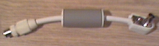
On the picture above you see the whole " J A-A Junction h�iri�adapteri" adapter from Suomen Radioamat��ritarvike Oy. The picture below is close up picture of the details inside the antenna isolator adapter:
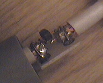
It had three turns of thin wire in promary and secondary wrapped around small ferrite core. The wiring inside the isolator is very similar to the audio isolator circuit, the only difference is that now connectors are antenna connectors and the transformer is the one designed for antenna signals (described above). The thin wires between the transformer and the coaxial cable are kept minimum to avoid the adapter to pick up interference.
If you live in Finland, you can buy this type of isolation adapter from SUOMEN RADIOAMAT��RITARVIKE OY under name J A-A Junction h�iri�adapteri televisioon. It costed 43 mk when I last checked the price (about 9 US dollars).
For more ideas how to fight against ground loop caused by cable TV connection, check the Fixing Cable-TV Hum in Audio Systems article by Jay Rose at http://www.dplay.com/tutorial/cablehum.html. Secrets of Home Theatre and High Fidelity web magazine reviewed an antenna wire ground loop isolator product UNHUMMER, so read the article if you are looking for an isolation device suitable for antenna network which is used in USA.
Simple two capacitor isolator
This circuit is a simple isolator for TV and Radio antenna connection. This circuit passes radio frequency signals nicely, but does not pass significantly 50 Hz signals, so the ground loop is eliminated. The circuit can be easily built into antenna connector or to a small box. I would recommend to use small metal box, where you connect one of the antenna connectors to the metal box and isolate other connector from box. Metal box allows mechanically strong contruction and provides good shielding against radio interference. The capacitors in the circuit should be rated at least 250VAC (400V DC) to make sure that the adapter with stands situation when antenna network ot television/radio is floating at mains live potential.
There is one disadvantage of this the circuit breaks the continuous shielding of the antenna cable which makes you antenna cable pick up radio interference more easily (for example radio interference picked by ground loop itself). Usually this is no big problem, but if you notice severe interference then you might have to stop using this isolator. The beast place tu put this isolator (to keep possibility of interference minimun) is just between TV receiver and antenna cable going to wall.
This capacitor isolator scheme might feel quite strange at the first sight, but it actually works and cuts the ground loop because it provides high impedance to low frequencies (50 or 60 Hz mains frequency) but has low impedance at the RF frequencies that are used at cable for TV channels. To eliminate the hum, you must insert a high impedance at 60 Hz. between the cable, its shield, and the audio-video system and at the same time provide a low impedance path for RF signals. The lowest signal frequency, for which the impedance must be very low with respect to the 75-ohm cable impedance, is around 50 MHz. That is about 1,000,000 times higher than 50 Hz. A 10 nF capacitor has an impedance of less than 1 ohm at 50 MHz and over 200 000 ohms at 50 Hz. Therefore, isolating the cable's center conductor and shield each with a 10 nF capacitor from the input to the cable tuner will eliminate the 60 Hz ground loop current and resultant hum without attenuating the RF signal level.
Capacitor isolator approach is an old trick used in TV industry. When the old TVs had their chassis at mains potential, they used this kind of approach to make sure that the dangerous voltage can get to the cable from the TV but the RF signal goes nicely to TV. Isolator used in one old TV had 330 pF 500 VAC capacitor which connects the center of the coaxial cable to tuner and the shield of the coaxial cable was connected to TV chassis through 820 pF high voltage feedthrough capacitor (value unknown).
A commercial isolator which plugs to TV cable made by JEBSEE uses 11 nF capacitor for connecting coax cable center wire and 22 nF capacitor to connect the shields together.
The easiest way to build the isolator is to use two chassis-mount antenna cable connectors (typically EIC antenna connectors on Europe and F-connectors on USA). Connect the center pins with one 10 nF capacitor and use the connectors' mounting nuts to connect a second 10 nF capacitor between the bodies, making sure that the connectors don't touch. You can then wrap the center with tape or put heat shrinking plastic tubing on it. This construction is a little flimsy but it won't get any stress, and the leads will be shorter than if you used a plastic box to mount the connectors, thus reducing the possibility of picking up RF interference. When constructiong the circuit remeber to keep all the component leads very short (remeber that you are dealign with very high frequency RF signals which can easily radiate out of circuit on even wuite short wires and those wires can pick up interference as well. or use a very small plastic box for the whole circuit.
Transformer isolator using two baluns
There is an alternative approach to antenna isolation problem: use transformer as in audio lines. The problem is to how to make a good transformer for antenna signals. If the transformer causes impedance mismaches, this can cause signal reflections which disturb you and maybe your neighbours also.
One way to do it is to use readily availabe 75 ohm to 300 ohm transformers (called "baluns" or "matching transformers") used when connecting old televisions with 300 ohm antenna input to modern antenna network with 75 ohm connectors. Those units are readily available from TV shops.
Notice that some 300/75 baluns are true (isolated) transformers, while others have a common ground. You can use the former type to break a CATV ground loop, but not the latter. So be sure to buy models which have no galvanic connection between 75 ohm input and 300 ohm output (so there is isolation between input and output), because some models only do impedance matching but galvanic no isolation (they are useless in this project). If you use an ohmmeter between the input and output you will find that there is a very low resistance between *all* the terminals if there is no isolation and open circuit if the balun transformet provides galvanic isolation.
The circuit is easy to build. Just take two of those 75 to 300 ohm
antenna transformers and connect their 300 ohm sides together. Now
you have antenna isolator you need.
           ____________               ____________
        __|            |------X------|            |__
75 Ohm |__             |  300 Ohm    |             __| 75 Ohm
          |____________|------X------|____________|
This circuit has been suggested by Paul Grohe ([email protected]), who
suggested that suitable transformers are available from Radio Shack
(Radio Shack cat. #'s 15-1140 and 15-1253 or MCM #33-050 and #33-010).
LiveDV magazine suggests using Radio Shack #15-1140 and #15-1523 antenna transformers wired together in their
Soundings: Getting Wired tutorial (January 1996).
According some comments I have recieved some people have pointed
out that the not all Radio Shack 75-300 baluns are not isolating,
so the above circuit might not work as epected. I don't
have access to those component from Radio Shack, so I can't
check what is the real situation. I have received mixed message
on both failing to get the circuit to work as expected (no isolation)
and some that the circuit works well ((Radio Shack cat. #'s 15-1140
and 15-1253). It is hard to say for sure what is the problem
(could the product with same code vary in this sense though
product code staus same). It is best to test by
outself that the baluns you plan to use are really isolating.
If the balun is isolatating can be tested with multimeter:
measure the reistances between all input and output pins.
If there is no conenction found between input and output,
then this balun is suitable for this circuit.
If you experience radio interference picked by this circuit, you can
can try the following method to make shilding ogh the circuit better:
You can wrap the whole little assembly in aluminium foil and ground the
foil to the "cable" cable shield. But don't let it touch the other ground.
                      Aluminium Foil Shield
                +--------------------------------+
                |    +--------+      +--------+
--Cable Co Coax-O----| Balun  |======| Balun  |--------  To TV
                |    +--------+      +--------+
                +--------------------------------+
                 connect to shield of incoming coax
Tomi Engdahl <[email protected]>