Mains connections
3 phase distribution
The most common way toi distribute high power to building is 3 phase system. That 3 phases system has advantages that it saves wiring copper and is very suitable for driving powerful electric motors. The wiring is designed so that it need that the power takem from each phase should be about equal. This is done by connecting all high power loads to all three phases and distributing all smaller loads eventually to those three phases.
Three phase power has three "hot" wires, 120 degrees out of phase with each other. These are usually used for large motors because it is more "efficient", provides a bit more starting torque, and because the motors are simpler and hence cheaper. The 3 phase wiring is usually used in electrical distribution because the power can be carried with a little bit less copper than with single phase distribution (especially when the load is well balanced).
The power comes from the power company through 4 current carrying wires: 3 phase wires and neutral wire. If the current is exactly matched in all phases, there is no current flowing in neutral wire. The neutral wire is connected to the building ground in the central mains distribution panel where is the building main grounding bar.
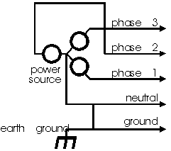
From the main central distributibution panel there goes 5 wires to the subpanels. 4 current carrying wires are 3 phase wires and neutral wires. Safety ground is a spearate wire which also goes to the central grounding bar like neutral wire. The difference of neutral and safety gound wires is that neutral wire does carry current in normal operation (the difference of currents taken from each phase) but safety ground does not carry any current in normal operations. This separation guarantees that in normal operation the whole safety ground wire is in building ground potential. This 5 wire wiring system is basically good and it is used in most buildings and places where ground loops are expected to be a problem.
All distribution of 3 phase voltage inside of building should be done using 5 wire system to avoid grounding potential difference problems. Distribution of 1 phase power should be done using 3 wire system. The safety ground wires should be interconnected in star or tree like fashion.
Three phase distribution in Europe
Three phase distribution is a very common in big houses (offices, shops, factories etc.) where lots of power is consumed and big motors are quite propably presents. In Finland and many other countries 3 phase distribution (230V from phase to ground and 400V from phase to phase) is very common in even smaller houses (typical house in Finland has 3x25A three phase main feed).
Three phase power most oftehn used in permanently wired electrical equipments like electrical ovens and large motors. In normal residental homes there are no normally anu power outlets for 3 phase power. In places where there is need to power equipments which consume more power than what is available from one mains outlet, there are usually 3 phase connectors available. Examples of this kind of places are constructuction sites, factories, places where large electrical tools are used and entertainment venues (for large PA system and lights). The most common 3 phase outlet you might to see is 16 ampere 3 phase 400V (voltage between phases) outlet which uses round red CEE 17 connector. Other popular models of this same round red connector can handle 32A, 63A and 125A.
Three phase distribution in USA
You're most likely to encounter a 3 phase circuit that shows 110 volts between any hot and ground, and 208 volts between any two hots. Those 3 phase distributions are commonly used in place where there are large motors or otherwise much consumption of electricity. Examples of this kind of places are factories, big shops, large office houses and similar buildings.
Getting a 3 phase feed to your home house in USA can be ridiculously expensive or impossible. Residential houses are typilly wired using "normal 220/110 wiring" where there are two 110V live wires (180 degrees in phase with each other) and they share a common neutral wire. Normal electrical outlets are wires between one 110V live wire and the common neutral wire. Some high current loads (air conditioning etc.) are wired between two phase wires so they get full 220V voltage.
Grounded outlets
While you may initially assume the three pronged cords to be inherently better, due to their ability to introduce multiple grounds to the audio system, they actually serve to further complicate the ground looping problems. Three pronged grounded outlets are better for electrical safety. Grounded outlets they are also good when the electrical distribution and audio wiring is well designed and constructed.
The 3-wire system that the user sees is actually derived from three phase distribution, which uses a 5-wire system. In the 5-wire system, there are 3 hot wires, 1 neutral wire, and 1 grounding wire. The common 3-wire receptacle uses only one of the 3 hot wires.
A typical office wall outlet has three electrical connections, which are the "hot", "neutral", and "grounding" wires. All office equipment requires only the hot and neutral wires to function. The third or grounding wire is connected to exposed metal parts on the equipment. Within the building, the grounding connections of all electrical receptacles are wired to one another and are connected to the water piping. This ensures that all electrical equipment with exposed metal parts has these parts electrically connected to each other and to exposed metal fixtures in the building such as water fixtures.
The hot and neutral wires are interchangeable as far as the equipment is concerned. Both are power carrying wires. One of the power carrying wires is grounded for reasons of safety.
Grounded equipments
Grounded equipment wired from mains voltage has three wires going to the equipment: live, neutral and ground. Live wire is one of the the phase wires from the 3 phase distribution systems. Neutral and ground wires are the same as in 3 phase distribution systems. The equipment load is connected between the live and neutral wires like in the picture below:
Here the two upper wires are the live and neutral wires. There is not much difference which one of those is live and which one is neutral because modern equipments are designed so that this does not matter. In some countries the power connector is designed so that you always know which wire has live and which has neutral in it. In some countries (for example Finland) the power connector is designed so that it can be put to the connector in two ways.
The third wire (the lowest one) is the ground wire. The ground wire goes to the equipment metal case and is there for giving safety to the user. When the metal case is tighly connected to the ground through the grounding wire then if there is something wrong in the equipment (like broken insulator or water leaks inside equipment) you just blow the fuse instead of getting lethal voltage to the case.
Grounding system is carefully designed so that it provides safety to the user. This includes the color coding that the safety ground wire is never mixed with any other wire (nowadays the safety ground wire must be alway yellow-green colored in Europe). The electrical connectors must be designed so that the safety ground connects before other pins and disconnects last. When wiring the safety ground wire to connectors the wire to it must be a little bit longer than what goes to other pins so that if the cable gets loose it is the last one which looses the connection,
Connectors used in grounded equipments
USA mains connector
The power supply cord used on most modern electronic equipment has a three pin plug (NEMA 5-15). The connector has place for two flat power pins for live and neutral wires and third round pin is ground. Typican mains receptable in wall in USA nowadays is a grounded 15A power outlet. A correctly installed receptacle should always be vertical with the ground pin beneath the two parallel blade slots.

There is also a 20A version of the mains connector which is used in some heavy equipments where 15A of 120V power is not enough.

Many new buildings in USA are equipped with "Isolated ground" receptacles. These are normally recognizable because they are bright orange and have a triangle marked on the face. Basically, these receptacles have a separate "green wire" equipment ground, and the wire goes back directly to the circuit breaker panel, without being connected to anything else. Isolated ground receptacles are installed in the hope that electrical noise generated in the building, or by other pieces of equipment, will not disturb the operation of delicate computer equipment plugged into them.
The black (hot ) wire goes to the brass or copper screw which is connected to the right (smaller) slot The white (neutral) wire goes to the silver or chrome screw which is connected to the left (larger) slot. The bare wire(ground) goes to the green screw for the separate ground path. These connections should always be made by a qualified electrician!
IEC connector
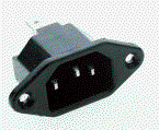
IEC connector is a standard international mains connector used in equipments like computers, printers, fax machines and many other grounded quipments which have removable power cord. The same connector is used in both 120V and 230V equipments. The connector can handle voltages up to 250V and current up to 10A.
SCHUKO
Finland, Sweden, Germany and many other European countries use a SCHUKO mains connector (CEE 7/7) in grounded equipments. The connector provides two pins for carrying live and neutral wires (current up to 16 A).
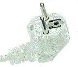
The grounding is most commonly done using the small bare metal parts on the sides on the the connector (you can see one near the pace where the wire leaves and another on the the opposite side). There is also a hole for a separate grounding pin used in some countries.
UK style grounded mains connector
Maybe the most common electrical outlet used around the worls is the UK style 3 pin mains connector (BS 1363). That connector is used in UK, Ireland and most of the countries which were once part of the British imperium. This makes this mains connector maybe the plug which is used in most countries.
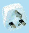
This connector is designed so that it can be only fitted in the wall in one way so it is laways know which pin is which. The toltally metal pin (up in the picture) is the ground pin. Those pins which have part of them insulted are the live and neutral pins. The speciality in the wiring used in UK is that there is a fuse placed inside the mains plug. The size of that fuse is to protect the equipment wire from overheating in case of short circuit (fuse size is determinded by the equipment wire size) because the main fuse which powers many electrical outlets is typically quite large (up to 30A). The maximum current which can be taken from one outlet is 13A.
Ungrounded equipments
Many small home electronics and light equipments designed for use inside house do not use grounding. Those equipments are built using double insulation or insulating case so that danger of electric shock is prevented in this way. Ungrounded power connection needs only live and neutral wires.

Connectors used in ungrounded equipments
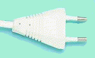
The most common connector in small electronics in Europe is so called EURO connector and is standardized in EN 50 075. This connector is designed so that it can be used in most parts of Europe. EURO mains connectors can typically handle only 2.5 ampreres of current. Typically the connector is a molded plug which is permanently connected to the cable and the plug can only be bought with the cable included.
Mains plug used in USA
Ungrounde plug is quite commonly used in small light and home electronics like TVs, VCRs etc.
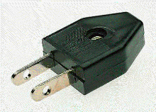
Nowadays, many two-prong devices have one prong wider than the other. This is so that the device could rely (not guaranteed!) on one specific wire being neutral, and the other hot. This is particularly advantageous in light fixtures, where the the shell should neutral (safety), or other devices which want to have an approximate ground reference (ie: some radios).
Many television and stereo components as well as appliances are being fitted with polarized plugs which have a wider spade for the neutral line cord wire. In some equipments a "bypass capacitor" which is wired between the white (neutral) wire and the equipment chassis ground. Capacitor offers a relatively low impedance to high frequencies (such as generated by radio stations and CB. radios) thereby providing them with a "short path" to ground in order to eliminate this type of interference and offers a high impedance to low frequencies (not much mains current passes through it so there is no significant shock hazard). Neutral wire is not very good ground in radio frequencies so this connection might cause more problems than it solves. Sometimes the coupling capacitor from the neutral to the case can be up to 0.1 uF and if the neutral and live are for some reason swapped you can get over 4 mA of current flowing to the equipment case. This kind of arrangement that live and neutral wires are handled differently inside equiments has not been recommended by international safety regulations for long time but it has been allowed practice in USA.
If you determine that you have a hot chassis with a system connected like this the solution is to simply reverse the plug (if you can can). Reversing the plug can sometimes solve interference problems. In some instances in transformerless consumer receivers where the case was connected to the neutral side of a polarized a-c plug via a 0.1 uf capacitor. Since at the mains the neutral is grounded, there may develop a small potential between the amp case and (extended) mains ground. If there is any heavy power draw in the vicinity of the same circuit, the potential may increase if wiring conductivity has decayed for various reasons.
Tomi Engdahl <[email protected]>


