ePanorama.net - Infrared remote controlling
IR remote control computer interfacing
This article tries to get you some idea how to interface IR remote controllers to computer. Possible applications could be controlling your computer your TV's remote control or controlling your VCR using computer.
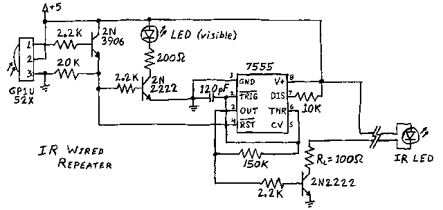
IR repeater circuit
This circuit was posted to sci.electronics newsgroup long ago. This circuit has been very useful to me because I based my first IR remote control experiments on this circuit. With some little modification the transmitter part of this circuit can be used with computer. The idea is to cut the wire going to 7555 IC pin 4. Connect the wire end coming form receiver to computer input and the end going to 7555 chip pin 4 to one computer output (computer inputs and outputs should be TTL level signals).
Famous Xanadu Zapper IR computer interfacing circuit
This circuit is a good example how to do the computer to IR remote interfacing in both ways. All you need is a simple program for sampling the data coming form receiver (few kHz sample rate is enough). When you want to control something, then just send the sampled data to the transmitter part of this circuit.
The circuit can be easily connected to PC parallel port for your experiments. If you are experimenting only with reception, then one good idea might be to connect the receiving part of the circuit to joystick port, because there are easy to use input lines and also poer for the whole circuit.
Article about interfacing
Newsgroups: sci.electronics
From: [email protected] (Dave Platt)
Subject: Re: Infra Red Retransmitters - For Remote Controllers.
Organization: New Technologies Group, Inc.  Palo Alto CA
Date: Mon, 28 Feb 1994 04:00:25 GMT

>1)Several receptors in parallel (arranged in order to have at least
>270 degree range)
You can probably use the little receiver modules made by Sharp, and marketed by Radio Shack (among other places), in a sort of wired-OR arrangment. Sony TV sets do this internally... the IR receiver is in a wired-OR arrangement with the chip which decodes the front-panel pushbuttons, and the "guts" of the TV simply listen to this signalling bus for their commands. On my KV-20XBR, at least, the control board of the TV literally cannot tell whether a button-press was on the front panel or on the IR remote... it's all bits on a Control-S/SIRCS bus by then!
>2)An amplification stage to drive the output IR led.
>
>3)The output IR led.
General recommendations:
[1] Use one of the IR receiver/demodulator modules (or several, in parallel) to receive and clean up the signal, and use this signal to switch a 40 kHz oscillator on and off. Do _not_ try to receive, amplify, and retransmit the modulated carrier directly... you will probably find that you circuit is extremely noise-sensitive and difficult to "trim". The receiver modules have a tuned 40 kHz amplifier circuit built in, which eliminates _lots_ of noise.
[2] You'll probably want to use a tunable oscillator (such as a CMOS 555 or something like that), and use the oscillator's output to drive a power transistor (a MOSFET works well), and have the power transistor drive one or more IR-LEDs in parallel.
[3] You can probably get decent retransmission using a 555 tunes to 40 kHz. However, you may get somewhat better retransmission if you run the oscillator at 80 kHz and divide down by two before driving your IR-LED - this will give you a 50% duty cycle rather than the 33%/66% duty cycle of a typical 555 circuit. The closer you get to 50%, the more easily your retransmitted carrier will get through the tuned filter in the receiver.
--
Dave Platt    [email protected] ..or.. ...netcomsv!ntg!dplatt
      USNAIL: The 3DO Company, NTG division
              2470 Embarcardero Way
              Palo Alto CA 94303


