


ePanorama.net - Joystick Documents
PC joystick interface circuits
Index
- Fake Joystick circuit
- The wire between multi-IO card and joystick connector
- Adding second joystick to PC joystick interface
- Y-cable problems with soundcards and how to solve them
- Soundcard joystick port problem solver
- Build your own joysticks and controllers
- Convert Atari-style joystick to PC joystick port
- Use PC joystick port to measure temperature and light levels
- Connect other circuits to PC joystick port
- Using the joystick port as general purpose input
NOTE: There is no guarantee as to the suitability of said circuits and information for any purpose whatsoever other than as a self-training aid. I.E. If it blows your equipments, trashes your hard disc, wipes your backup, burns your building down or just plain don't work, IT ISN'T MY FAULT. In the event of judicial ruling to the contrary, any liability shall be limited to the sum charged on you by us for the aforementioned document or nothing, whichever is the lower.
WARNING: There is lots of current (many ampreres) available on the PC joystick port without any built-in current limiting. Short circuit on the circuit connected to PC joystick port can cause wires heating, burn thin circuit board traces, crash your computer, damage your PC power supply and even catch fire. I have burnt one flatcable going from PC multi-IO-card to the joystick connector because of short in circuit connected to joystick port! So if you make mistakes your multi-IO-card or soundcard can be in the line to suffer sudden joystick port death. Usually you should be quite safe with if you do not short circuit +5V output to anything and do not apply any external signals to PC joystick port.
TIP: If you want to play with the joystick interface safely without danger of frying anything you should put some kinf of current limiting device in series with the +5V output on the connector which plugs to your joystick port. One way to do that is to put a 100mA..1A fuse in series with the +5V output. If somehing goes wrong, the fuse will blow and no damages are caused. Another possibility is to connect a current limiting resistor in line. A resistor of around 100-500 ohms (at least 1/4W power rating) soldered directly into the 'D'-type solder bucket (short lead wire, sleeved and no solder-shorts to nearby pins!) will make no practical difference to the joystick circuit operation and bring the worst case circuit current down to the mA region.
Joystick connector wirings
Fake Joystick circuit
The following very simple circuit can be used to make the computer
to think that there is a real joystick connected to joystick port.
This adapter might be useful in some special computer testing
applications when you don't have real joystick available.
     pin 1      +5      ________________
                                        |
                              100k      |
     pin 3      stick 1x ____/\/\/\_____|
                                        |
                              100 k     |
     pin 6      stick 1y ____/\/\/\_____|
Actually an even simpler circuit will also work:
     pin 1      +5      ________________
                                        |
                                        |
     pin 3      stick 1x _______________|
                                        |
                                        |
     pin 6      stick 1y _______________|
The wire between multi-IO card and joystick connector
Some PC multi-IO cards have a 16 pin header in the circuit board which is wired to the joystick connector (fitter to other slot place) using flatcable.
The wiring is straight one-to-one connection but, due to the different numbering scheme of the gameport connector vs the 16-way header, the pin numbers don't necessarily match (pin 16 in header is ocource lef not connected because joystick connector has only 15 pins).
Joystick connector pinout (15 pin D connector)
        9 10 11 12 13 14 15
        o  o  o  o  o  o  o

      o  o  o  o  o  o  o  o
      1  2  3  4  5  6  7  8
16 way header (pin 16 not connected)
        2  4  6  8 10 12 14 16
        o  o  o  o  o  o  o  o

        o  o  o  o  o  o  o  o
        1  3  5  7  9 11 13 15
Pin-1 of the header goes to pin-1 of the gameport, but
pin-2 of the header goes to pin-9 of the gameport. etc..
The pinout is done this way so that manufacturer can easily make up a connector using IDC ( Insulation displacement ) connectors.
The description above seems to be atleas tru in the multi-IO cards I have seen (your's might be different if you have bad luck).
Adding second joystick to PC joystick interface
PC joystick interface was designed to support two joysticks, but unfortunately it has only one connector. The second joystick can be added when you get a special Y-cable, which has connectors for two joysticks. Those cables can be bought ready-made from nearly any good computer store, but can be easily made if you already have the parts. If you decide to build Y-cable yourself, make it well and avoid possible short circuits (+5V line can give quite remarkable amount of current in short circuit and burn your wiring).
Some other manufacturers have made joystick interfaces which have two connectors. Some manufacturers have saved few cents in their multi-io cards and impelemented only the electronics of the joystick one.
Y-cable
                             |----------15-pin female f1
------------------           |
| 15-pin male m1 |-----------|
------------------           |----------15-pin female f2
  m1                                 f1    f2
-----------------------------------------------------------
1 : +5vDC                            1
2 : Stick 1 button 1                 2
3 : Stick 1 X-position               3
4 : Gnd                              4
5 : Gnd                              5
6 : Stick 1 Y-position               6
7 : Stick 1 button 2                 7
8 : +5vDC                            8
9 : +5vDC                            9     1
10 : Stick 2 button 1               10     2
11 : Stick 2 X-position             11     3
12 : Gnd                            12     4 and 5
13 : Stick 2 Y-position             13     6
14 : Stick 2 button 2               14     7
15 : +5vDC                          15     9
Y-cable problems with soundcards and how to solve them
Jystick connector typical PC sound card is not fully compatible with the original PC joystick interface, because soundcard manufacturers have replaced pins 12 and 15 with the MIDI interface pins. If the joystick or joystick adpater you connect to soundcard useds those pins, then it will not work properly with soundcard joystick interface. I think that it was quite stupid choice form Creative Labs to put the MIDI signals to the Soundblaster's joytick interface, and then all other manufacturers have copied this stupid idea. It seems that the manufacturer's customer support is typically unaware of this incompatibility and great deal of problems this causes to many users. Typical problem are that some joysticks doe not work properly and even in worst case the soundcard doughterboard stops to work when some otherwise well working joystick is connected to the joystick port.
It is possible to build an adapter wich enable using two joysticks
or joystick with pedals on soundcard interface.
D15S (male)----------D15S(female)
to soundcard---------to joystick
 1------------------------1
 2------------------------2
 3------------------------3
 4------------------------4
 5--------------------+---5
 6--------------------|---6
 7--------------------|---7
 8--------------------|---8
 9 ----+--------------|---9
 10----|--------------|--10
 11----|--------------|--11
 12    |              +--12
 13----|-----------------13
 14----|-----------------14
 15    +-----------------15
When you have built this interface, you can then use any standard joystick
or joystick Y-cable with it. If you heap up your soldering iron to make your own adapter,
then why not make a complete workign joystick Y-cable using the following modified
wiring scheme which works with the soundcards also.
Soundcard                         stick1  stick2
-----------------------------------------------------------
1 : +5vDC                            1     1
2 : Stick 1 button 1                 2
3 : Stick 1 X-position               3
4 : Gnd                              4     4
5 : Gnd                              5     5
6 : Stick 1 Y-position               6
7 : Stick 1 button 2                 7
8 : +5vDC                            8     8
9 : +5vDC                            9     9
10 : Stick 2 button 1               10     2
11 : Stick 2 X-position             11     3
12 : MIDI
13 : Stick 2 Y-position             13     6
14 : Stick 2 button 2               14     7
15 : MIDI
For those who are looking for ready-made cable, go to your computer store and ask for "Joystick Y cable". Many manufacturers make this type of cable, the best known cable might be Gravis "Y" Cable.
Soundcard joystick port problem solver
Typical PC soundcards (for exampel Sound Blaster family) has added MIDI interface to the joystick connector by using pin 12 for MIDI output and pin 15 for MIDI input. This causes sometimes problems with some joysticks and adapters which work pefectly on standard joystick port. The following conversion circuit enables standard joystick Y-cables to be used with soundcards without problems. This circuit provides GND to pin 12 and +5V to pin 15 as in original PC joystick interface. This enables using standard Y cables and joyticks with extra functions (like pedals) to be used with soundcards without problems like some of the joystick functions not working properly or the MIDI doughterboard does not work when joystick is installed.
D15S (male)----------D15S(female)
to PAS-----------------to joystick
 1------------------------1
 2------------------------2
 3------------------------3
 4------------------------4
 5--------------------+---5
 6--------------------|---6
 7--------------------|---7
 8--------------------|---8
 9 ----+--------------|---9
 10----|--------------|--10
 11----|--------------|--11
 12    |              +--12
 13----|-----------------13
 14----|-----------------14
 15    +-----------------15
NOTE: Do not try to connect your soundcard MIDI adapter after
this circuit ! Connecting MIDI adapter to this circuit can damage it.
Electronics projects for joystick port
Build your own joysticks and controllers
Building your own normal PC joystick is not economically wise, but if you can't find a joystick you would like to have, then you have te consider doing it yourself. The connections inside PC joystick are quite simple to do, the harder part is the mechanics. Buttons are quite easy to mout to the case you use when you select suitable buttons, but the problematic part is geeting the stick movement to move the slider in the potentimeter. Commercial sticks use different mechanical constructions for getting the stick movement to rotating or linear motion.
If you manage to get the stick movement to rotation which you can connect to normal potentiometer, then the problem is tha normal potentiometer have rotation of about 270 degrees and the sticks moves normally much less than 90 degrees. So you will not be able to use the whole scale of the potentimeter. You can solve this problem by using 470 kohm linear potentiometer instead on 150 kohm potentiometer. In this way you get nice 0-100 kohm value range when you use only first 60 degrees of potentiometer. Some commercial stick use this method.
Pedals
Build Your Own Cockpit page contains lots of rudder and pedal building projects. For example check Rudder Pedals, Throttle and Y-cable page. Check also Lew's Wheels.
Steering wheels
You can find a nice steering wheel circuit diagram and construction ideas at http://www.monmouth.com/~lw4750/.
Tips for building your own gamepad
Here are some tips if you want to try to implement your own gamepad like Gravis Gamepad for PC or similar.
The gamepad works so that the movement plate has four switches (up,down,left,right) below it. When you pus it to some direction, one or two of those switches are pressed down. The keypresses are converter to resistance values usign the follwing table:
   +----------------------------------------------+
   � x = 0 kohm   �  x = 50 kohm  �  x = 100 kohm �
   � y = 0 kohm   �  y = 0 kohm   �  y = 0 kohm   �
   +--------------+---------------+---------------�
   � x = 0 kohm   �  x = 50 kohm  �  x = 100 ohm  �
   � y = 50 kohm  �  y = 50 kohm  �  y = 50 ohm   �
   +--------------+---------------+---------------�
   � x = 0 kohm   �  x = 50 kohm  �  x = 100 kohm �
   � y = 100 kohm �  y = 100 kohm �  y = 100 kohm �
   +----------------------------------------------+
You can generate the necessary resistance values for example with the following circuit:
              +------100kohm--------+
              |                     |
   +5v >------+-----SW1----100kohm--+----> joystick  potentiometer out pin
              |                     |
              +-------SW2-----------+

Where:
SW1 = NC, normally closed switch (opens when this direction is pressed)
SW2 = NO, normally open switch (closes contacts when pressed)
Here is another circuit which works in exactly in the same way:
                     +---SW1----+
                     |          |
+5V >----+--50kohm---+--50kohm--+-----> joy pot out
         |                      |
         +--------SW2-----------+

Where:
SW1 = NC, normally closed switch (opens when this direction is pressed)
SW2 = NO, normally open switch (closes contacts when pressed)
NOTE: Those circuits can't be built with two normally open switches. If your joystick has or gamepad you want to modify has such switches then check my Convert Atari-style joystick to PC joystick ports circuit instead.
Circuit operation
For X-direction you do not press anything when you are on center. If you want to go right you pree SW1 and if you want to go to left you press SW2. +5V power can be taken from PC joystick port pin 1 and the output is connected to pin 3.
Same circuit idea applies for Y direction. You need need to build a second circuit where for down direction SW1 is closed and for up SW2 is closed. +5V power can be taken from PC joystick port pin 1 and the output is connected to pin 6.
The buttons are connected to gamepad like normal PC joystick buttons. Connect the normally open (close when pushed) switches between the joystick port pins mentioned in the following table to make them to work:
Switch 1     pins 2 and 4
Switch 2     pins 7 and 4
Switch 3     pins 10 and 4
Switch 4     pins 14 and 4
For a complete joystick wiring (using a little different component values) take a look at Connect an Arcade Joystick to your PC project at http://www.zeta.org.au/~msmcdoug/joystick.html.
Building gamepad with just normally open switches
When you are building gamepads youself, in many cases you are often stuck with switches witch are normally open. Elvir Mulahmetovic has sedigned the following circuit to allows you to use just switches witch are normally open. The circuit is very simple.
The circuit has been included to this document with the permission from Elvir Mulahmetovic.
Convert Atari-style joystick to PC joystick port
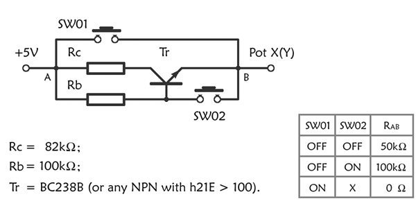
Some games are easier to play with digital joystick instead of analogue type. Unfortunately PC has only analogue joystick connector, which makes it impossible to connect normal digital joystick to it. But with a little adapter circuit, it is possible to use Atari style digital joystick with IBM PC joystick interface. The circuit adapts the joystick connectors and converts digital joystick movement signals to analogue signals. The circuit can be used with any PC game to replace the original analogue joystick. The circuit also simulates also Gravis Gamepad operations except the extra buttons.
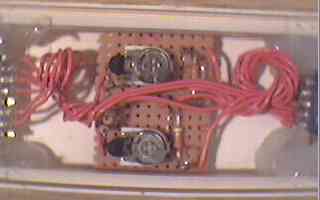
The joystick adapter can be quite easily built to a small plastic box which can be easily fitted between the PC joystick adapter and the joystick you wish to use. On the picture below you can see my protoype.

I built my prototype to a small piece of veroboard. I have not designed any real PCB for this project, so you have to design your own PC or build your own circuit to some protyping board. Take a look at the inside of my prototype to get ideas how to lay out the components in your circuit. On the left side you see the 15 pin male connector and on the right there is 9 pin male connector. Both connectors are glued to the case using hot glue.
Component list
R1,R3,R4,R6   2.2 kohm
R2,R5         100 kohm
T1,R2         BC557
D1,D2         1N4148
P1,P2         100 kohm trimmer
CON1          9 pin male D connector (joystick side connector)
CON2          15 pin male D connector (PC side connector)
Tips on replacing the components with other types
If you happen to be in USA and have problem on getting the necessary components then you can replace BC-557 with Radio Shack product 276-2023 and 1N4148 with Radio Shack product 276-1122. This replacement tip is based on the information I have received from Radio Shack product support. I have not tried myself how well the circuit will work with those components, but I have received reports that the circuit works nicely with those components. In case you can't get even those components, then you can try almost any general purpose PNP transistor in place of T1 and T2 (for example 2N3906 seem to be quite similar, I have not tried that).
Generally the circuit is not very sensitive to the component differences on diodes and transistors. Generally almost any small signal transisotr with Hfe on range of 100-500 should do the job. For the diode you can use almost any common diode, like very popular 1N4001 rectifying diode.
Placing the components on the circuit board
I have not designed a circuit board for my circuit, because I only needed to build one such circuit and it was easy to build to veroboard. The circuit is not very sensitive to any noise or interference, so you can quite freely place the components on the veroboard as you like. The following circuit board layout (designed by Peter Larsen from Denmark) which you can use as an example for your own circuit board or for designing the way to put components to veroboard. If you want to have a larger view of the circuit board, click the picture to get it enlarged.
The circuit operation
The interface circuit directly connects the joystick buttons to the corresponding PC joystick connector pins because they operate similarly in both joystick types. Because PC need different resistances to X and Y inputs to know the joystick position, the circuit converter the four switch inputs form the Atari stick connector to the different X and Y resistance values which are the outputted to PC joystick port. The circuit gives the following resistance values from the 9 different positions an Atari-style joystick stick can have:
                            UP
       +----------------------------------------------+
       � x = 0 kohm   �  x = 50 kohm  �  x = 100 kohm �
       � y = 0 kohm   �  y = 0 kohm   �  y = 0 kohm   �
       +--------------+---------------+---------------�
 LEFT  � x = 0 kohm   �  x = 50 kohm  �  x = 100 ohm  �  RIGHT
       � y = 50 kohm  �  y = 50 kohm  �  y = 50 ohm   �
       +--------------+---------------+---------------�
       � x = 0 kohm   �  x = 50 kohm  �  x = 100 kohm �
       � y = 100 kohm �  y = 100 kohm �  y = 100 kohm �
       +----------------------------------------------+
                           DOWN
The resistance values are exactly the same as what is given by
PC gamepad controllers
(like Gravis Gamepad for PC)
or what normal PC analogue joystick give out when it is in
center position or in any extreme position (fully moved to one
of the eight main directions).
The different resistance values are generating using following method (this example is for forward/back direction movevement):
- When the digital joystick is in center position the current flows through R3, D1 and potentiometer. When potentiometer is tuned center position the PC joystick interface seen around 50 kohm resistance. No current flows through T1.
- When the Forward switch is closed the point between R3 and D1 is grounded. Now the current can only go to PC joystick interface though the potentiometer, which give 100 kohm resistance.
- When Forward switch is closed then current starts to flow from T1 emitter to base and then through R2 to forward switch. This base current causes that T1 starts to conduct from emitter to collector so the PC joystick interface sees very low resistance.
Left/Right movement conversion works in exactly the same way. Normal digital joystick button is wired to Button 1 input in PC joystick interface and one extra button in digital joystick connector is wired to the Button 2 in PC joystick interface.
NOTE: The transistors and and diodes are absolutely necessary for this circuit to work. You can't avoid using active circuit elements if you want to to convert and unmodified Atari joystick to PC josytick port. I know that there are some simple circuits which use only few resistor to adapt joystick to PC, but those can't be used with unmodified Atari joysticks. They require you to completely rewire internals of the joystick (which is not always possible as shown in their circuit diagrams). The intention of my circuit was to make the circuit general and avoid any changes needed inside the joystick.
Tuning the circuit
When you have built the interface, you have to set the trimmers to correct positions.The potentiometers must be set so that the circuit shows 50 kohm to joystick interface when the joystick is in the center position. So first align the potentiometers just to the center position. If you want to more accurate alignment, use a simple test program to align those more accurately. The aligning procedure is very simple: just urn tje joystick to left and right positions and calculate the average of those values the test program shows. The align the potentiometer so that the circuit gives the calculated value when joystick is in the center position. Do the same to the forward/back direction.
Modification idea: Getting more buttons to work
Because the use of extra buttons in joystick is not standarized, what pins are used on those depend on the computer, it is possible to make a circuit which works well with all kinds of button arrangement, you need to do some experimenting to get the second butotn to work. If for some reason the circuit as it is does not work, it might be possible that your joystick uses pin 9 for extra button, instead of pin 5, you must do a small modification to the circuit to get the system work. A simple modification is to move the wire going to pin 5 on 9 pin connector to pin 9 on the same connector.
Another idea which you can try is to keep the wire on pin 5, but add an extra wire which connects pin 5 and 9 together. This causes that all extra button (no matter are they connected to pin 5 or 9) are recognized as button 2 on PC joystick port.
Modification idea: Adding support for more buttons
The circuit supports two buttons in the original configuration. Atari joystick normal fire button is wired to PC joystick button 1. For atari-style joysticks which have one extra button the adapter supports wiring the extra button as PC joystick button 2. You can easily add support for third button support by awwing a wire from 9 pin connector pin 9 to pin 10 on the 15 pin connector on the PC. For fourth button there is no place for in in 9 pin joystick connector, so you must add in in some other nonstandard way. You can add this extra button by wiring it between pins 14 and 4 in the PC side 15 pin connector.
Other similar projects
A quite similar joystick adapter building project by Heikki Kosola can be found at http://www.students.tut.fi/~k150585/joyport-en.html. That designs uses a slightly different circuit and also includes the picture of the PCB for two digital joysticks. That document is also available in Finnish at http://www.students.tut.fi/~k150585/projektit.html.
Use PC joystick port to measure temperature and light levels
Pc joystick port can be used very easily for simple measurement of light
and temperature values. All you need for light measurements is to connect
a LDR resistor between +5V and potentiometer input. For temperature
measurements substitute the LDR with suitable NTC-resistor. If you
use only one input, put a 0..100 kOhm resistor to other input so that
the computer don't think that there is no joystick available (this is
for those that use BIOS routines or some other ready-made library).
Here is thje
     pin 1      +5      ________________
                                        |
                            NTC or LDR  |
     pin 3      stick 1x ____/\/\/\_____|
                                        |
                              100 k     |
     pin 6      stick 1y ____/\/\/\_____|
Select the variable resistor (NTC or LDR) type so that is will give resistor values are in 0..100 kOhm area in your measurement situations. The larger difference between smallest and largest resistor value, more accurate the system will be. The problem is that the system will never be very accurate, because the joystick interface is not degigned to be very accurate instrument. The value given you get can vary from component temperature drift, large differences between diffrenet joystick interface cards, computer clock speed differences and some other things. I have tested the system with some LDR resistors and one NTC resistor taken from a small electronic thermometer.
You can't make very fast measurements with this method (limited by joystick port technology), because each measurement takes normally arount 1 to 2 milliseconds. You can test your own circuits using my joystick test program. You can see how X position value of the joystick 1 will change according the value you measure. Remeber that the value changes are not typically lienarly related to the temperature or the light intensity. The rensponse of LDR and NTC resistors is typically some exponential response (you can try to match an exponetial curve to some measured values you get).
Connect other circuits to PC joystick port
PC joystick connector provides easily usable four TTL level inputs
(with pull-up resistors) and four resistive inputs. Using those
inputs is very simple as you can see from the joystick circuit or the circuit diagram below:
     pin 1      +5      ________________
                                        |
     pin 3      stick1x ________        |
                                | 100K  |
                            _/\/\/\_____|
     pin 6      stick1y ________        |
                                | 100K  |
                            _/\/\/\_____|
     pin 11     stick2x ________        |
                                | 100K  |
                            _/\/\/\_____|
     pin 13     stick2y ________        |
                                | 100K  |
                            _/\/\/\_____|
                              ___
     pin 2      button1 ______o o_______
                              ___       |
     pin 7      button2 ______o o_______|
                              ___       |
     pin 10     button3 ______o o_______|
                              ___       |
     pin 14     button4 ______o o_______|
                                        |
     pin 4      GND     ________________|
PC joystick port can be a very useful interface for simple digital input circuits, because joystick connector has +5V power output, which other standard PC interface connectors don't have. You need to be a little bit careful with this power output, because it can give quite much current in short circuit situation (up to 20A in some cases). This current is enough for burning small wires in your circuit or inside your PC (I have burned one flatcable coming form multi-IO card to joytick connector !).
I have connected succesfully a light sensor, magnetic card reader, bar code reader and infra-red remote control receiver to PC joystick port. Joystick port has been also an useful power source for some other projects connected to other ports.
If you have problems in accessing you own circuits connected to joystick port using some ready made joystick routines (for example BIOS routines or routines in operating system), check that your circuit looks like the real joystick in all aspects. If the analogue inputs (or even one of them) in the joystick port are left not connected anywhere, the joytick routine might think that there is no joystick attaced. So be sure that there is always resistance of 0..100 kohm between all analogue inputs of the joytick used and +5V power connector (for more details, check the joytick schematic).
For those who can read Finnsih can check PC:n peliohjainportti ja omatekoiset anturit article which is available at http://www.helsinki.fi/~aohamala/joystick/peliportti.htm.
Using the joystick port as general purpose input
The following circuit idea is based on PCTIM003 FAQ / Application notes: Timing on the PC family under DOS by Kris Heidenstrom and is included here with the permission from the author.
The joystick button inputs can be used as general purpose button or switch inputs, and can also be driven by logic level signals or by open collector or open drain logic outputs. If used with a signal direct from a mechanical contact (e.g. a switch, microswitch, contact, or pushbutton), remember that the joystick port does not perform hardware debouncing, so this must be provided by external hardware or provided by software.
Provided that you can tolerate poor accuracy, poor repeatability, poor matching between channels, and poor temperature stability, you can use the joystick position inputs as general purpose analogue inputs, but don't fart too close to them. The inputs should not be voltage-driven, they should be driven from a variable resistor from a positive supply rail such as the 5V rail (the way the joystick itself works), or from a positive variable current source. This gives a roughly linear relationship between resistance and time measured, which means an inverse (reciprocal) relationship between current and time measured.
A voltage signal can be converted into a variable current signal, and a circuit to do this is given in Figure 5 in the FIGURES archive. This circuit converts a positive, ground-referenced voltage into a positive current source that can be fed into one joystick position input. The relationship between input voltage and output current is linear. 1V on the input produces an output current of 1mA. The circuit requires a 9-12V supply, which is unfortunately not available on the joystick port, though you could use a switched capacitor voltage booster (e.g. the Linear Technology LT1054) or a switching supply (e.g. the Motorola MC34063 or the National Semiconductor LM2574 series) to produce a higher voltage rail from the 5V output on the joystick port, but be aware that switching power supplies can create a lot of electrical noise.
The picture below is the circuit diagram of the voltage to joystick input converter. If you want a larger view on the circuit diagram, then click the picture to enlarge it.
Because the relationship between input voltage and time measured is reciprocal, a zero input voltage will give an infinite timeout. Obviously this should be avoided, as it will prevent software from reading the inputs within a reasonable period of time. This can be prevented by ensuring that the input voltage never falls below a certain threshold, or it could be prevented by incorporating an offset in the voltage to current converter. In the very unlikely event that you are interested in pursuing this, I may be able to help so please drop email message to Kris Heidenstrom.