


ePanorama.net - Joystick Documents
PC analogue joystick interface
Index
- Introduction
- Joystick connector
- How PC joystick port hardware works
- Programing support of PC analogue joystick port in DOS
- Useful tool programs
- Programming joystick in Windows
- Programming joystick in Linux
- Information sources
Introduction
Nowadays the most common analogue joystick type is PC analogue joystick. This joystick model was presented by IBM together with their first IBM PC computer. The joystick is just a basic analogue joystick with two buttons. The original joystick interface had circuit for connecting two joysticks, but had only one joystick connector. A special Y-cable was needed if there was need for two joysticks at the same time. Later time some manufacturers put two connectors to their interface card and some card manufacturers implemented only one joystick input. Fortunately most of the card nowadays have option for two joysticks like the original IBM joystick card.
The joystick interface card was designed to be as simple and cheap as possible. The card consisted only of bus interface electronics and four monostable multivibrators (all in on 558 chip). Those monostable multivibrators were simple timer circuits which put out a pulse with width directly proportional to the joystick resistance value. The pulse width was then measured using software loop. This has caused anormous amounts of problems to game programmers when computers have become faster and faster all the time. On faster machines, the joystick routine in the software does not read the joystick signal properly resulting in a timing problems. Some dedicated joystick cards are designed to vary the joystick signal so the software can properly detect the joystick and process the data.
Joystick construction
The joystick consists of two potentiometers with variable resistance value between 0 Ohm and 100 kohm (in some joysticks up to 150 kohm). The potentiometer resistances have the minimum values when the joystick is at the top left position. One end of the potentiometer is connected to +5V pin and the center pin is connected top the analogue input of the joystick. The other end of the potentiometer is left not connected to anywhere.
There are two commonly used ways how PC analogue joystick stick mechanism is constructed. Some joystick convert the stick position to linear motion, whcih then changes the position of the slider in about 100 kohm linear potentiometer. More popular construction is to use normal axial potentiometers and the joystick movement directly turns those potentiometers. Some joystick used special 100 kohm potentiometer which can only turn that 60..90 degrees which joytick can turn. The more common construction is to use the standard 470 kohm (lin) 270 degree potentiomer and use about one fourth of the scale from the beginning (in this way getting 0..120 kohm value range). Usually those potentiometers are normal carbon slider potentimeters which do not last long in intense gaming.
Joystick connector
Pinout
(male connector on joystick cable)

        .-----------------------.
        \ 8 7  6  5  4  3  2  1 /
         \ 15 14 13 12 11 10 9 /
           ~~~~~~~~~~~~~~~~~~~
  1  XY1 (+5v)
  2  Switch 1
  3  X1
  4  Ground (for switch 1)
  5  Ground (for switch 2)
  6  Y1
  7  Switch 2
  8  N.C.
  9  XY2 (+5v)
 10  Switch 3
 11  X2
 12  Ground (for switch 3&4) *
 13  Y2
 14  Switch 4
 15  N.C. *
Some I/O cards have implemented only the first joystick functions: X1, Y1, Switch 1 and Switch 2. Some joystick adapter have +5V output also in pin 8.
* Many soundcards have joystick interfaces with midi port function enbedded to the same connector. Those midi port impelemtations use pins 12 (midi data output from computer) and 15 (midi data input to computer). The midi cable includes the necessary electronics for signal conversion and isolation. That's a nonstandard way of using the pin and it may cause problems in some cases (some functions of the joyticks are not working or sound card does not even work correctly when certain joyticks are used !). Here is the joystick port pinout used in PC soundcards (Soundblaster, Gravis Ultrasound and many other):
pin     purpose
1       potentiometer common            (Joy A)
2       button 1                        (Joy A)
3       X coordinate potentiometer      (Joy A)
4       button common                   (Joy A)
5       button common                   (Joy B)
6       Y coordinate potentiometer      (Joy A)
7       button 2                        (Joy A)
8       unused
9       potentiometer common            (Joy B)
10      button 1                        (Joy B)
11      X coordinate potentiometer      (Joy B)
12      MIDI TXD (transmit)             (computer -> midi)
13      Y coordinate potentiometer      (Joy B)
14      button 2                        (Joy B)
15      MIDI RXD                        (midi -> computer)
          Joystick B             ____      Joystick A
                                /    |
                              /      |
                            /        |
                          /       1  |
                         |        O------- 5 Volt
              5 Volt -------O        |
                         |  9     2  |
                         |        O------- Button
              Button -------O        |
                         |  10    3  |
                         |        O------- Resistor X-axis
     Resistor X-axis -------O        |
                         |  11    4  |
                         |        O------- Ground
            MIDI TXD -------O        |
                         |  12    5  |
                         |        O------- Ground
     Resistor Y-axis -------O        |
                         |  13    6  |
                         |        O------- Resistor Y-axis
              Button -------O        |
                         |  14    7  |
                         |        O------- Button
            MIDI RXD -------O        |
                         |  15    8  |
                         |        O------- 5 Volt
                          \          |
                            \        |
                              \      |
                                \    |
                                  \__|
Typical PC joytick circuit diagram and inside picture
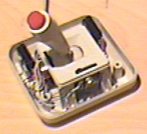
Potentiometers used in paddles are usually few hundred kilo-ohm linear potentiometers (max. 470 kOhm). Potentiometers are connected between +5V and input pin.
How PC joystick port hardware works
The joystick port is a very simple 8 bit I/0 card which resides in ISA bus I/O address 201h. The CPU can read and write to the joystick port I/O address 201h. Writing to that address starts joystick postition measurement. Joystick interface only uses the signal that somebody is writing to the I/O address to reset the multivibrators in the card. The data value is not stored anywhere, so it is really same what value is written to this address.
When you read one byte from I/O addess 201h, you get the status information of the joystick interface. The following table will show how the bits are mapped in the value you get.
 Game port 201h byte:
         _______________________________________________________
        |   7  |   6  |   5  |   4  |   3  |   2  |   1  |   0  |
        | but4 | but3 | but2 | but1 | stk4 | stk3 | stk2 | stk1 |
        |______|______|______|______|______|______|______|______|
The four most significant bits tell you the state of the joystick buttons.
Four least significant bits tell the state of the multivibrators which are
used for measuring the resistance value of the joytick position potentiometers.
More accurate description of the bit meanings can be found at the table below:
7 6 5 4 3 2 1 0
* . . . . . . .  Button B2 (pin 14), 0=closed, 1=open (default)
. * . . . . . .  Button B1 (pin 10), 0=closed, 1=open (default)
. . * . . . . .  Button A2 (pin 7), 0=closed, 1=open (default)
. . . * . . . .  Button A1 (pin 2), 0=closed, 1=open (default)
. . . . * . . .  Monostable BY (from pin 13), 1=timing, 0=timed-out
. . . . . * . .  Monostable BX (from pin 11), 1=timing, 0=timed-out
. . . . . . * .  Monostable AY (from pin 6), 1=timing, 0=timed-out
. . . . . . . *  Monostable AX (from pin 3), 1=timing, 0=timed-out
Resistive analogue inputs (joystick position)
Joystick position inputs are simply inputs where a variable 0-100 kohm joystick
potentiometer is connected to. The potentiometers are wired between the +5V power
pin and one potentiometer input pin. The following picture tries show how
the wiring is done:
                +5      ________________
                                        |
                stick1  ________        |
                                | 100K  |
                            _/\/\/\_____|
                stick2  ________        |
                                | 100K  |
                            _/\/\/\_____|
                stick3  ________        |
                                | 100K  |
                            _/\/\/\_____|
                stick4  ________        |
                                | 100K  |
                            _/\/\/\_____|
The resistance value of the joystick potentiometers are measured using very simple
monostable multivibrator circuit, where a small capacitor is loaded through the
joystick potentiometer to a certain voltage level. The joystick interface has
four this type of monostable multivibrators. Typically joystick interface multivibrators
are all in one 558 IC (that IC is like four simplified 555 type timers in one IC)
for two joystick ports and 556 (dual 555 timer) for one joystick only port.
  Joystick
   Pot in  >---+
  (stick n)    |
               \
       R1      /        ____________
       2.2K    \       |            |
               /       |            |>----------> data bit to ISA bus
               |       | Monostable |out
               +-------|   Multi-   |
               |       |  vibrator  |
       C1     ---      |            |<----------< write to I/O port strobe
       22 nF  ---      |____________|trigger
               |
               |
              ---
NOTE: Reference design in Crystal Semiconductor CD4376B calls recommends C1 to be 5.6 nF and R1 to be 2.2 kohm for their soundcard reference design.
The multivibrator work on the following way:
- 1. Normally on idle state the capacitor C1 is fully charged (5V) and multivibator output gives out logic 1.
- 2. Computer writes to I/O address 201h to reset the multivibrators. The multivibrator get a triggger pulse from I/O write signal and it discharged capacitor C1. The multivibrator output goes to logic 0 because the capacitor is discharged (0V).
- 2. The capacitor starts to charge form the current which goes through R1 and the joystick potentiometer.
- 3. When the capacitor voltage reaches certain oltage threshold level, the multivibrator output goes back to logic 1.
This simple joystick port hardware implementation (originally designed for 4.7 MHz IBM PC) causes many headaches to game programmers (problems of different computer speeds, joycitck port differences, problems in multitasking operating systems etc.). Big tolerances in joysticks and joystick ports mean that the every game must have an option to cablibrate the joystick (which actually means that the program adapts to accept the values in th range which the joystick reading routine does and then converts the values to it's internal format using the values measured in joystick calibration process).
Switch inputs (joytick buttons)
The joystick buttons are simple on/off inputs. Joystick button either leaves the
pin floating or connect it to the ground.
                              ___
                button1 ______o o_______
                              ___       |
                button2 ______o o_______|
                              ___       |
                button3 ______o o_______|
                              ___       |
                button4 ______o o_______|
                                        |
                GND     ________________|
The state of the buttons is directly fed to the joystick interface and through
it to ISA bus data lines when somebody reads the joystick interface I/O address.
The buttons are very easily wired. Every input has 1 kohm pull-up resistor R1
which ensires that the joystick button pins stay in +5V potential (logic 1)
when no button is pressed down.
                      +5V
                       |
                       \
                       / R1
                       \ 1K
                       /
   Joystick            |
   button in  >--------+-------------------------> data bit to ISA bus
  (button n)
NOTE: Reference design in Crystal Semiconductor CD4376B calls for 4.7 kohm pullup resistor and 1000 pF capacitor from input to ground.
When one button is pressed down, that input is grounded which caused the voltage on that pin goes to 0V which means that the joystick interface then gets logic 0 form that input. If you just keep reading the joystick port I/O address contantly, you will get a real-time sate of the button pins.
Circuit diagram of PC joystick interface
The following circuit diagram is from PCTIM003 document and is Copyright by K. Heidenstrom. This picture is included in this document with permission from K. Heidenstrom.
This circuit block diagram applies to all PC joystick interfaces from multi-IO cards to PC soundcards. In PC soundcards the pins 12 and 15 are used by MIDI interface which has it's own electronics separate from the joystick interface.
The 558 chip used in PC joystick adapter is a quad version of a popular
555 universal timer chip. If you are not already familar how 555 universal
timer operates then it is worth to check
555 timer chip datasheet. The 555 timer is used as
one-shot in the joystick adapter circuit.
Because the pinout of 558 is a little bit hard to find on databooks
here is 558 pinout for those whi want to hack their joystick adapter
electronics:
       +---+--+---+
    1Q |1  +--+ 16| 4Q
1RCext |2       15| 4RCext
   1TR |3       14| 4TR
    CV |4       13| /RST
   VCC |5  558  12| GND
   2TR |6       11| 3TR
2RCext |7       10| 3RCext
    2Q |8        9| 3Q
       +----------+
Is there any way to get any output from joystick port ?
There is no such function as turning the joystick port pins on/off ever designed to joystick port. Joystick port is designed as input only port.
The joystick port does not need the data you send to it (it is simply discarded). The only thing in data write operation which is needed is the data strobe signal (which comes from the ISA bus when data is ready to be read by card) triggers the monostable multivibrators which are used in converting the resistance of the joystick potentiometer to pulse length.
When the multivibrators are triggered then in normal joystick poer implementations this causes one side-effect: when the monostable multivibrator is triggered then it discharges the timing capacitor by shorting it to ground for very short time. Then the capacitor is discharged by the monostable multivibrator or is charged by the current from the joystick port there is some current flowing through the joystick potentiometer input pin (that current dicreases over time until the capacitor is fully charged to +5V).
So in typical joystick port you can detect some pulses by measuring the current flowing to joystick potentiometer input pin: every time the joystick card is written the current flow into all joystick potentiometer input pins will increase to maximum value (set by external resistor and the internal resistances in the joystick card) and then starts to decrease then time goes on. That's the only way to get anything out of joystick port.
Some digital joystick with their own special digital communication protocols use this joystick port feature to send some data and/or syncronization information from computer to joystick.
Programing support of PC analogue joystick port in DOS
I the beginning there was not ready made BIOS routines for reading joystick in IBM PC. That's why every programmer had to do their own routines. Since IBM AT, joystick routines have been a standard part of BIOS routines. But long time game manufacturers had to use their own routines, because they couldn't rely that the computer had BIOS support for joystick.
Bios functions
INT 15 - BIOS - JOYSTICK SUPPORT (XT after 11/8/82,AT,XT286,PS)
        AH = 84h
        DX = subfunction
            0000h read joystick switches
                Return: AL bits 7-4 = switch settings
            0001h read positions of joysticks
                Return: AX = X position of joystick A
                        BX = Y position of joystick A
                        CX = X position of joystick B
                        DX = Y position of joystick B
Return: CF set on error
            AH = status
                80h invalid command (PC,PCjr)
                86h function not supported (other)
        CF clear if successful

Notes:  if no game port is installed, subfunction 0000h returns AL=00h (all
          switches open) and subfunction 0001h returns AX=BX=CX=DX=0000h
        a 250kOhm joystick typically returns 0000h-01A0h
The BIOS joystick reading function (as many other joystick reading routines) locks out interrupts for more than aroun 1 ms at a time and may cause problem of lost or too much delayed interrupts. When the interrupts have been delayed too much there can be problems with device buffers (buffer under/overflow, break in data transfer or sound playback). For some accurate timing routines when interrupts are missed the time period can be extended.
Note that changing the divisor and/or operating mode of CTC channel 0 may break the BIOS's joystick reading functions.
Example for using BIOS routine for reading joystick button state
Call int 15h with:  AH = 84 hex
                    DX = 0000 hex
Call returns:       AL = Button states in bits 7-4, as read from input port
Bits 7-4 are valid in the returned value, and they default to '1' and are '0'
if the corresponding button is currently depressed. This function does not
perform any debouncing on the joystick button inputs. This means that the
bit may 'bounce' (i.e. alternate randomly, one or more times) at the instant
that it makes or breaks contact, because of the mechanical nature of the
switch.
Example for using BIOS routine for reading joystick position
Call int 15h with:   AH = 84 hex
                     DX = 0001 hex
Call returns:        AX = Joystick A, axis X (0-511, 0 if timed-out)
                     BX = Joystick A, axis Y (0-511, 0 if timed-out)
                     CX = Joystick B, axis X (0-511, 0 if timed-out)
                     DX = Joystick B, axis Y (0-511, 0 if timed-out)
This function reads each of the four inputs separately, disabling interrupts for
a few milliseconds each time. It may use CTC channel 0 for timing, and if so,
its calculations will be affected if CTC channel 0 is operating in a differently
than the BIOS has originally set it to operate.
For reasl source code examples I would recommend you to check the my JOYTEST program Turbo Pascal sourcecode and the source code for a small library it uses.If you are more familar with C, then check the joystick test program written in C by Jack Morrison.
Note that many joysticks return non-linear values, i.e. the value returned at centre-position is not half way between the values returned at corner positions, so most joystick setup programs require the user to set up the centre position as well as the corner positions. It is advisable to use a 10% 'dead zone' around the centre, as joysticks do not always centre repeatably. Joysticks are and joystick sadapters are not high quality devices, and some smoothing on the position values may help if the values are moving around randomly.
Your own routines
To read the joysticks (or your slide pot positions), you must first write a byte to port 201h. It doesn't matter what value you send, as long as you perform an I/O write. This triggers the 558 timer on the game adapter.
 Game port 201h byte:
         _______________________________________________________
        |   7  |   6  |   5  |   4  |   3  |   2  |   1  |   0  |
        | but4 | but3 | but2 | but1 | stk4 | stk3 | stk2 | stk1 |
        |______|______|______|______|______|______|______|______|
The most machine-independent way to sample the game port is to use a timer. Note the time (e.g., read the countdown register in Timer 0, you need pretty fine resolution and this timer performs 65535 counts every 55 ms) just before you trigger the 558. After triggering, sit in a loop reading port 201h and examining bits 0-3. For those bits that have a joystick pot attached, you'll see them sit for a while at 0, then become 1. As each bit flips back to 1, note the time again. When all bit 0-3 have flipped back to 1, you're almost done. Compute elapsed time for each bit, and you end up with a value that is proportional to pot position.
Pots are normally 0-150k variable resistors (0-100k sometimes), and according to the IBM techref, the time is given by Time = 24.2e-6s + 0.011e-6s * R/Ohms. This equation does not accurately represent the real situation, where theare are differences in absolute components values. In reality you have to calibrate the joystick for the application you use. Thse most straighforward way to calibrate the stick for the program isto record the values the joystick gives in extreme positions and in the center position.
Buttons can be read at any time just by reading port 201h and looking at bits 4-7. No triggering is required. Button bits are normally 1; while a button is depressed, its bit will flip to 0.
More information about accurately measuring time using PC can be found at "Timing on the PC family under DOS" document written by Kris Heidenstrom. That documents comes with example source code also. All this is available in on zip packet at ftp://garbo.uwasa.fi/pc/programming/pctim003.zip.
Low-overhead joystick LEFT/RIGHT and UP/DOWN detection idea
If you simply want to detect whether the joystick is left or right of centre, or above or below centre, and don't want the overhead of locking interrupts for several milliseconds at regular intervals, you could use a fast tick interrupt to poll the joystick port. One idea would be using an interrupt at about 500 us and working cyclically through three states. On one interrupt, trigger the joysticks.On the next interrupt, read the monostable states. On the next interrupt, do nothing. On the next interrupt, you're back to the first interrupt again, so trigger the monostables again. This will give a left/right and up/down indication every 1.5 ms, with a fairly low overhead.
Useful tool programs
I have written an simple joystick tester program which I have found to be useful in many simple electronics tests. The program is a simple DOS test program which shows the information of both joystics easily readable on the screen. The program is useful in testing joysticks and your own project.
The program is easy to use. Just download this program and run this under DOS. The program used BIOS routines to read the joystick, so the computer must be at least AT class (286 processor) to be able to run this program. The sourcecode is also freely available for those who are interrested in how to read joytick using Turbo Pascal. You need binary.tpu to compile the program so take also the binary tpu source code.
For those who prefer C can check the joystick test program written in C by Jack Morrison.
CH Producs has a free JCENTER.EXE joystick testing and centering program in their Tech Support Web page
PC Game Programmer's Encyclopedia has a good Programming the PC Joystick article which includes technical info and source code in Turbo Pascal and Assembler. Good assembler josytick reading routine examples can be found at PCTIM003 FAQ / Application notes: Timing on the PC family under DOS.
Programming joystick in Windows
In Windows there are few different ways to read joystick. For Visual Basic programmers one polssibility is to use Lib "winmm.dll" calls joyGetPosEx and joyGetDevCaps.
In modern games joyticks are read using DirectX gaming API. DirectInput part of DirectX provides functions for reading various game input devices including joysticks. DirectInput is nowadayd the recommended API for game controlling devices over the current standard API functions because it support for more types of devices and faster responsiveness Microsoft� DirectInput� provides an interface for a variety of input devices (joysticks, headgear, multi-button mice, force-feedback joysticks etc.). By working directly with device drivers, DirectInput bypasses the Microsoft� Windows� message system.
Moving Your Game to Windows article series describes keyboard, mouse and joystick inputs. Moving Your Game to Windows, Part II includes the joystick programming information and includes source code for it. You can also find information from May the Force Feedback Be with You: Grappling with DirectX and DirectInput article from Microsoft Systems Journal.
Some more links:
- Computer Game Developers' Conference - DirectInput slides
- Designing HID Game Controllers for DirectInput
- Wellcome to DirectInput - slide set
Programming joystick in Linux
The Linux Programmer's Guide mentions joystick programming briefly at chapter 9.4. The joystick is supported lin Linux kernel by joystick reading loadable kernel module. There is an example program js.c in the joystick loadable kernel module package <linux/joystick.h>. There are some ioctl calls related to joystick:
- JS_SET_CAL
- JS_GET_CAL
- JS_SET_TIMEOUT
- JS_GET_TIMEOUT
- JS_SET_TIMELIMIT
- JS_GET_TIMELIMIT
- JS_GET_ALL
- JS_SET_ALL
Linux Joystick Driver has a web page at http://atrey.karlin.mff.cuni.cz/~vojtech/joystick/.
Information sources
- The Giant Internet IC Masturbator
- PC Game Programmer's Encyclopedia
- PCTIM003 FAQ / Application notes: Timing on the PC family under DOS by Kris Heidenstrom, Release 3
- Ray Duncan, IBM ROM BIOS, Microsoft Press 1988
- Sven Goldt, Sven van der Meer, Scott Burkett and Matt Welsh, The Linux Programmer's Guide, Version�0.4, March 1995