


SCART RGB interfacing to video projectors
RGB in SCART
SCART connectors used with many European video equipments is designed to carry composite video and RGB video signals. If the equipment which outputs picture outputs RGB-signal, it will putput RGB signal from the RGB pins and a complete composite video signal at the same time.
- If the receiving equipment uses RGB, it will take picture from RGB pins and sync from the composite video pin.
- If the receiving equipment understands only composite video, it will use the picture in it.
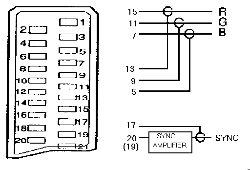
SCART pins used in RGB mode:
 5   RGB Blue Ground
 7   RGB Blue Signal  (0.7Vpp 75 ohm)
 9   RGB Green Ground
11   RGB Green Signal (0.7Vpp 75 ohm)
13   RGB Red Ground
15   RGB Red Signal (1Vpp 75 ohm)
17   Composite Video Ground
19   Composite Video Out (1Vpp 75 ohm)
20   Composite Video In  (1Vpp 75 ohm)
On pins 19 and 20 please notice that a typical standard SCART cable the pins 19 and 20 are crossed with each other. The equipment which outputs RGB or composite video signal, the composite video is available on pin 19 at the female connector on the back of the signal sending equipment. The same signal is then available on the pin 20 at the other end of the SCART cable.
The composite vidoe signal has amolitude of 1Vpp, which consists of 0.3Vpp composite sync signal plus 0.7Vpp picture signal.
SCART RGB to 4 BNC inputs
You might in some cases want to feed the RGB from SCART to some video equipment with other type of interface. One example of such equipment would be a video projector with RGB inputs with BNC connectors. The following wiring can be used for connecting an RGB signal from SCART connector to a video equipment with RGB and composite sync input.
The wiring needs an sync amplifier circuit, because the 0.3Vpp composite sync signal which is included in normal composite video signal is not generally stron enough for the sync inputs used in video projectors. Depending the projector, they usally need a sych with amplitude from atleast 0.5 to 2V to operate correctly. composte video to sync. This means that if you feed that composite vidoe signal directly then generally the video projector does not sync at all or does not sync reliably.
Sync sepatoration and amplifications electronics is almost always always needed to get the projector to work correctly. The following circuit can be used to do the sync separation and amplification.
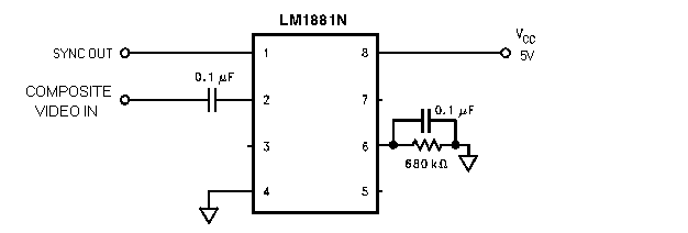
If you have hard time sourceing LM1881, you can replace with some compatible IC like EL 4581 or similar.
Projectors with VGA input
A video projector with only VGA style RGB connector might be a good candidate to try, but a normal PC monitors are out of questions (in SCART the HSYNC frequency is around 15.6 kHz but VGA monitors want atleast 31 kHz). Video projectors can usually handle the HSYNC rate used in normal video (15.6 kHz) without problem even on their VGA connector (check technical data or tech support to make sure of that).
If you display device can handle the picure sent out by SCART and your video source outputs RGB (your normal VCR does not output that, but video games and DVD players might be capable of this) the it might be possible to get nice RGB picture from SCART through VGA connector to the video projector.
What needs to be done is to convert the sync signals used in scart (composite video signal) to the sync signal wanted by VGA connector (TTL level separate sync) with some electronics.
Tomi Engdahl <[email protected]>