SCART RGB interfacing to video projectors
RGB in SCART
SCART connectors used with many European video equipments is designed to carry composite video and RGB video signals. If the equipment which outputs picture outputs RGB-signal, it will putput RGB signal from the RGB pins and a complete composite video signal at the same time.
- If the receiving equipment uses RGB, it will take picture from RGB pins and sync from the composite video pin.
- If the receiving equipment understands only composite video, it will use the picture in it.
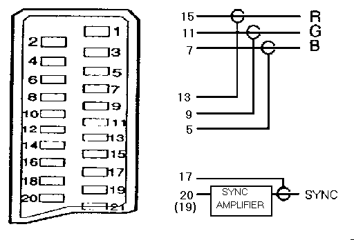
SCART pins used in RGB mode:
 5   RGB Blue Ground
 7   RGB Blue Signal  (0.7Vpp 75 ohm)
 9   RGB Green Ground
11   RGB Green Signal (0.7Vpp 75 ohm)
13   RGB Red Ground
15   RGB Red Signal (1Vpp 75 ohm)
17   Composite Video Ground
19   Composite Video Out (1Vpp 75 ohm)
20   Composite Video In  (1Vpp 75 ohm)
On pins 19 and 20 please notice that a typical standard SCART cable the pins 19 and 20 are crossed with each other. The equipment which outputs RGB or composite video signal, the composite video is available on pin 19 at the female connector on the back of the signal sending equipment. The same signal is then available on the pin 20 at the other end of the SCART cable.
The composite video signal has amolitude of 1Vpp, which consists of 0.3Vpp composite sync signal plus 0.7Vpp picture signal.
SCART RGB to 4 BNC inputs
You might in some cases want to feed the RGB from SCART to some video equipment with other type of interface. One example of such equipment would be a video projector with RGB inputs with BNC connectors. The following wiring can be used for connecting an RGB signal from SCART connector to a video equipment with RGB and composite sync input.

The wiring needs an sync amplifier circuit, because the 0.3Vpp composite sync signal which is included in normal composite video signal is not generally stron enough for the sync inputs used in video projectors. Depending the projector, they usally need a sych with amplitude from atleast 0.5 to 2V to operate correctly. composte video to sync. This means that if you feed that composite vidoe signal directly then generally the video projector does not sync at all or does not sync reliably.
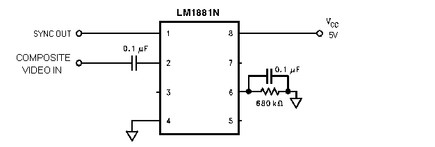
Sync sepatoration and amplifications electronics is almost always always needed to get the projector to work correctly. The following circuit can be used to do the sync separation and amplification.

If you have hard time sourceing LM1881, you can replace with some compatible IC like EL 4581 or similar.
Projectors with VGA input
A video projector with only VGA style RGB connector might be a good candidate to try, but a normal PC monitors are out of questions (in SCART the HSYNC frequency is around 15.6 kHz but VGA monitors want atleast 31 kHz). Video projectors can usually handle the HSYNC rate used in normal video (15.6 kHz) without problem even on their VGA connector (check technical data or tech support to make sure of that).
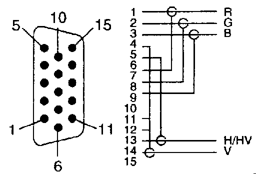
The VGA input connector pinout for using RGB input: (pins not needed in this application are not listed here)
1       Red in
2       Green in
3       Blue in
6       Red ground
7       Green ground
8       Blue ground
10      Sync ground
13      HSYNC in
14      VSYNC in
One possible wiring to feed RGB signal into VGA input is the same as used for VGA card to BNC monitor connection. The witing that can be used is the same. The the pinout drawing for the cable is for male connector side.

If you display device can handle the picure sent out by SCART and your video source outputs RGB (your normal VCR does not output that, but video games and DVD players might be capable of this) the it might be possible to get nice RGB picture from SCART through VGA connector to the video projector.
What needs to be done is to convert the sync signals used in scart (composite video signal) to the sync signal wanted by VGA connector (TTL level separate sync) with some electronics. Here is one design which is not complete design with all details explained (maybe there will be one here when I need the circuit myself):
Composite sync to HSYNC and VSYNC converter
Sync separation is a process quite often needed in video technology, but it is a little bit hard to find a chip which especially made for that. What you can find easily is a chip which takes a full composite video signal and outputs separate sync signals. Those chips can be directly used also with composite sync signal because it is just like a composite video signal without picture and has a little bith higher signal level. You can find a good list of such chips and links to their datasheets (which include example circuits) at http://www.epanorma.net/videochips.html.
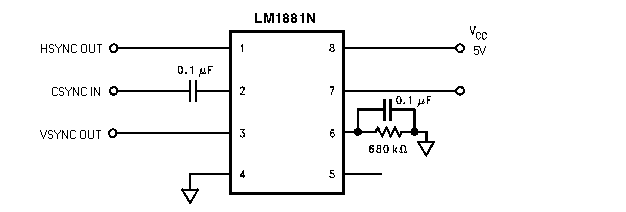
I have used the following circuit (based on example from datasheet) for separating composite sync signal for monitors which need different kind of sync than what your source gives. The circuit is based on very popular LM1881 sync separation IC.

When building this circuit remeber to connect the grounds of the signal input and output connectors to the signal ground (little triangle connected to LM1881 IC pin 4). Good ground connection is connect thei circuit to the sync signal ground on the connector. Connect also +5V power supply ground to this signal ground.
Features of the circuit:
- Circuit accepts composite sync signal at any level between 0.3Vpp and 5Vpp
- Circuit can accept sync from sync on green source if connected to green picture component line which includes sync signal
- Circuit can accept 1Vpp composte video signal as sync source
- Circuit works at least at 15kHz to 60kHz HSYNC range (tested at that range, might support higher frequencies)
- Circuit works on 50 Hz to 75 Hz HSYNC range (tested on that range)
- Circuit outputs TTL level negative sync signals
- Circuit consumes less than 100 mA current at +5V
- Circuit can also be used to to separate sync signal from composite video or sync-on-green signals (connect CSYNC input to composite video or green signal with sync in it)
The circuit have one serious drawback: The HSYNC output of the circuit is not really a HSYNC signal. To be exact the signal which the circuit outputs is TTL level composite sync signal. Many monitors accept that signal nicely as a HSYNC signal, but not all. For example Nokia 417X refused to show any picture when I connected HSYNC and VSYNC to it, but displayed nice picture when I disconnected VSYNC (that monitor definately can sync to composite sync signal and did it nicely when it received only that). SO if you have roblemss in getting your monitor to sync with both HSYNC and VSYNC connected then try your monitor with only HSYNC connected.
By adding a little bit more electronics it is possible to make a real HSYNC iput by wisely combining composite sync and VSYNC outputs from LM1881 using the following circuit which consits of two logig gates (one AND one one NAND):
           |--------------|----------------------  Composite (if you need
it)
           |              |    |-----\
           | |-----\      -----|      \
Composite ---|      \          | AND   |---------  Hsync
             | NAND  |o--------|      /
Vsync -------|      /          |-----/
           | |-----/
           |
           |-------------------------------------  Vsync
This circuit provided by
John A. Maier
eliminates any guess work on the Hsync line and guarantee it will
work with any VGA monitor.
If I would need to design a new circuit I would propably design it around some chips which has a real HSYNC output insted of just composite sync. One such IC which comes in mind is EL4583 from Elantec. This chip has a vrey suitable set of outputs: Composite sync, H sync, V sync plus 5 others.
NOTE: Before starting any circuit building projecs check if your monitor can also handle composite sync directly. Some monitors can do that (check your monitor technica data for information on this, some can accept composite sync if it is connected to only HSYNC or VSYNC input). In this case you need only to connect RGB lines directly to monitor and also the composite sync signal to right sync input.
Connecting SCART with no RGB output
Not all devices with SCART connector output RGB signals. For examples VCRs only output composite video (some can also output S-video). In order to connect composite video to RGB input the signal format needs to be converted to RGB. This need electronics which is quite complicated.
Many people have asked for this kind of conversion circuit through e-mail. I don't have a this kind of circuit project link available. You can find link to datasheets of composite video (PAL or NTSC) to RGB converters at http://www.epanorama.net/videochips.html#decoder. Some of them have some example conversion circuits in the datasheet. If you have a good idea of a good composite video to RGB converter circuit link, please e-mail me your tips on this and I add a link to here for the benefit of all.
Vellaman makes an electronics kit for converting PAL composite video signals to RGB and optinally back to composite video. That kit is K4600 VIDEO AND RGB CONVERTER/PROCESSOR. Might not be the cheapest option, but maybe worth of the try because it seems to be quite good quality product. I once though of using that kit for other applications, but finally solved the problems in other ways.
Tomi Engdahl <[email protected]>
 Back to index page


