Farnell/Newark/Element14 has been running a Conductive Ink Challenge with deadline of 31st August 2014. In it the competition the plan is to draw artistic circuits by hand using nickel or silver-laced “ink”. The aim is to make eye-catching piece of art. Judging is based on creativity, originality and technical and is final
To test conductive conductive ink pen I got an introductory packet to test the how it works, and hopefully produce something artistic. The introductory packet included pen and electronics component (including Arduino Uno board).
Conductive ink are inks that conduct electricity. Conductive inks have been used in automobiles for years and they are used in making printed electronics. Most conductive inks are made from silver. For some applications, nickel, copper, gold or other precious metals are used. Silver is popular because it’s more conductive than copper, which becomes less conductive as it oxidizes, and silver is less expensive than gold.
My introductory kit was supplied with CircuitWorks CW2200MTP (micro-tip pen) conductive ink pen. Chemtronics CircuitWorks Conductive Pen makes instant highly conductive silver traces on circuit boards and many other materials. The silver traces dry in minutes (tack-free in 3 to 5 minutes at room temperature, good electrical conductivity within 30 minutes). Before using the package recommends you to read Safety data.
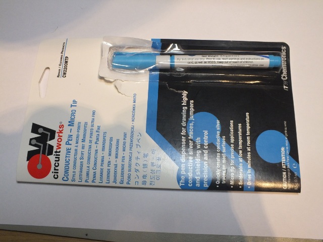
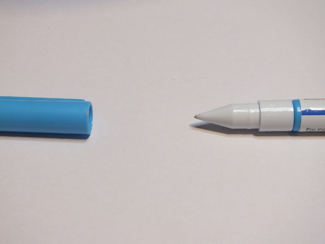
The CW2200MTP (micro-tip pen) has an orifice size of 0.7 mm and will draw traces that average 1.5 mm in width. It feels a suitable way to prototype or draw circuits by hand using silver-laced “ink”.
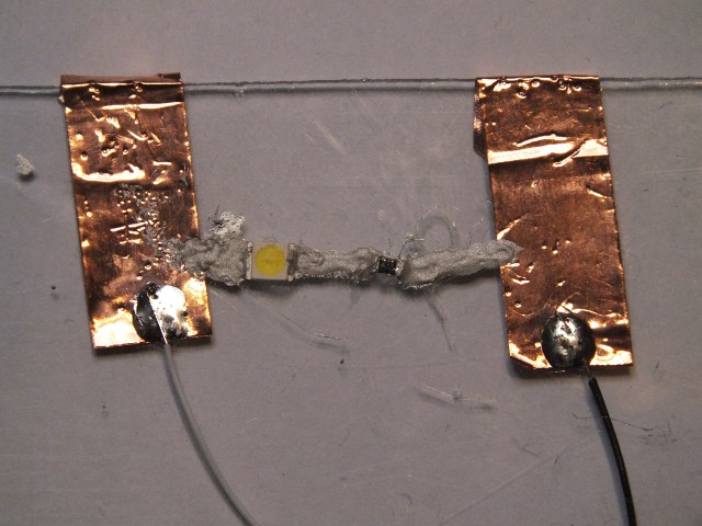
First test I did was to try to draw circuit traces to post-it note and add in one LED.
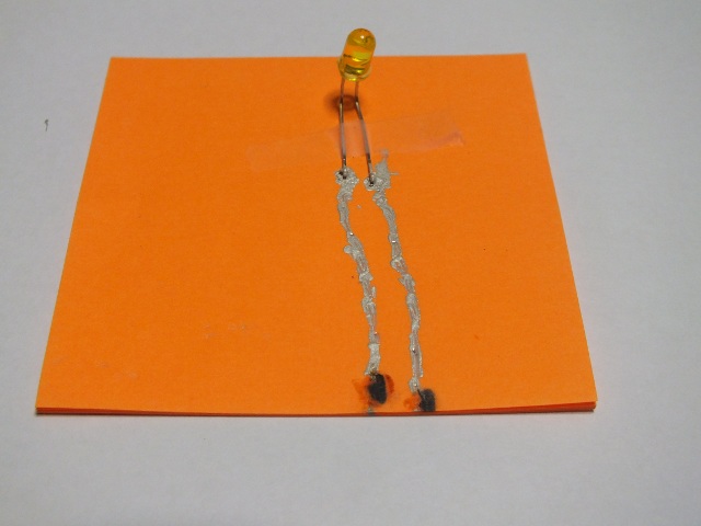
The left trace was around 10 ohm and the right one around 20 ohms. Quite a bit of resistance for quite short trace, but does not matter in this LED circuit too much. I supplied power to LED from 9V battery through resistors. Things went well when I supplied then the power with test cables. Things started to go wrong when I tried to solder wires to traces (I remember reading that temperature soldering is possible). Maybe my soldering temperature was too high for the conductive ink and the paper, because it was failure – result was just black spots where I tried to solder.
When testing different ways to use conductive ink pen to draw circuits, I found out that maybe the most useful method would be to glue the components to base material, and then draw the conductive traces between them. Normal though-home components bent suitable could work, but SMD components are usually easiest to use for this. Fortunately I had suitable SMD components so I could start testing. For test the main components I used were 270 ohm resistor and different SMD LEDs. The best construction method was first to glue the components in (gel 10 second super glue was very good glue for this) to their places, and then afterwards draw traces (or add wires where very low resistance was needed).
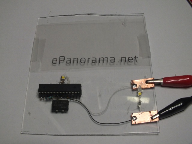
Then I got a too complex idea to implement well: How about drawing a nice ePanorama.net logo with LEDs and control them with minimal Arduino circuit? Build this on transparent piece of plastic. This sounded like a good plan to make an eye-catching “piece of art”.
Shrimping It page provided plans for very simple Arduino compatible platform building. Maybe those could be implemented with conductive ink… I already had programmed Arduino micro-controller from Arduino UNO supplied with the conductive pen evaluation package. I just needed to add IC socket and other components. All other needed components were easy to source from my components, but I could not find suitable 16 MHz crystal. Fortunately I found 16 MHz crystal oscillator that I could put it easily into circuit using tips from UNO Overdrive article.
But later trying to build Arduino with conductive ink was not so good idea. It turned out that it was hard to make very reliable connections from the IC to conductive ink traces. I had to give up the conductive ink Arduino idea. ![]() I ended up building tiny Arduino using mostly SMD components and traditional soldering. During the process also the conductive ink pen tip started to dry out. Most time I could not get anything useful from the pen, sometimes it barely worked. And the dead-line was coming. I had to make some of traces by opening the pen and trying to spread the paint to circuit other means. This took lots of work, was messy and the results did not look good. In the end due those problems I decided to simplify the circuit to something I could build: One flashing LED controlled by Arduino circuit and other LED that shows when power is on. Result did not look good, by anyways I had tried to make something on this competition.
I ended up building tiny Arduino using mostly SMD components and traditional soldering. During the process also the conductive ink pen tip started to dry out. Most time I could not get anything useful from the pen, sometimes it barely worked. And the dead-line was coming. I had to make some of traces by opening the pen and trying to spread the paint to circuit other means. This took lots of work, was messy and the results did not look good. In the end due those problems I decided to simplify the circuit to something I could build: One flashing LED controlled by Arduino circuit and other LED that shows when power is on. Result did not look good, by anyways I had tried to make something on this competition.
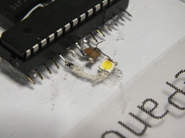
Close-up of one part made with conductive ink:
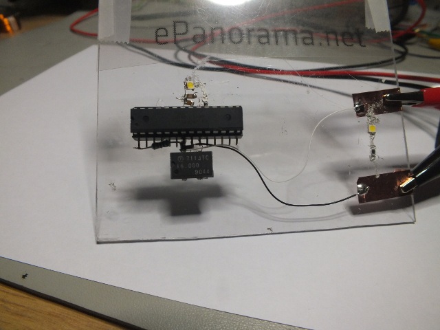
Final result showing the dirty results.
16 Comments
Tomi Engdahl says:
It seem that I was not the only one that failed with transparent circuit board making with conductive ink pen:
Fail of the Week: Transparent Circuit Design is Clearly a Challenge
http://hackaday.com/2014/10/09/fail-of-the-week-transparent-circuit-design-is-clearly-a-challenge/
He used nickel ink, which is slightly cheaper than silver ink. The ink was among the least of his problems, though.
[Frank] is going to have another go at it with copper foil and wider tracks.
Transparent Circuit Experiment Failure
http://eleccelerator.com/transparent-circuit-experiment-failure-20140604/
I wanted to make a transparent circuit, made with clear acrylic plastic, and the circuit pattern is etched onto the plastic using a laser cutter. The etching forms a groove that is about 0.1mm deep and 0.8mm wide, this groove is filled with conductive ink to form a circuit.
I attempted this experiment, but was met with…
…several difficulties. These problems are bad enough for me to not suggest this method.
ประตูม้วน says:
wonderful issues altogether, you simply gained a new reader.
What may you suggest in regards to your put up that
you just made a few days ago? Any positive?
Tomi Engdahl says:
Review: Voltera V-One PCB Printer
http://hackaday.com/2015/11/20/review-voltera-v-one-pcb-printer/
Back in Feburary, I was one of the first people to throw some cash at the Voltera V-One circuit board printer on Kickstarter. With an anticipated delivery date of Q4 2015, I sat back and waited. This week, my V-One arrived!
Opening the Voltera V-One app, you’re greeted with the “Hello World” circuit. Voltera ships the components for this simple board with the printer. It’s a little blinky LED design, consisting of a 555 timer, some LEDs, resistors, and a 9 volt battery.
The printing process has a number of steps, which the software guides you through.
Once the axes are calibrated, you load the conductive ink in and calibrate again. This calibration ensures that enough ink is dispersed to make continuous lines, while not causing those lines to overlap. The conductive ink is the equivalent of copper traces on a normal PCB, so the goal here is to ensure good connections and prevent short circuits.
Next, the conductive ink is printed. This took about 7 minutes for the Hello World board.
With the conductive ink on the board, it was time to bake it. This requires flipping the board over, and letting the V-One heat it up to about 220 degrees Celsius. The baking took a total of about 30 minutes, with another 10 minutes to cool off. The final step is to scrub the board with an included burnishing pad to prepare the surface for soldering.
Now that the Hello World board is printed, it was time to dispense solder paste. This is an interesting feature, because it can be used to dispense paste on any PCB, not just those made on the V-One.
With the paste on, it’s time to break out the tweezers and place the components. Hitting the reflow button in the app automatically starts heating the bed according to the reflow profile.
This unit is the 6th one delivered, and even had a nice “Development Unit” sticker on the packaging. I was expecting to get something pretty alpha. Overall, I’m impressed by the quality.
One concern with any tool like this is the consumables. The ink has to be purchased from Voltera, and it’s not clear if you can manually refill the syringes. The amount of ink you get with the printer doesn’t look like much, but it’s hard to tell how much printing can be done before re-ordering. You’re also buying into the company, since you’ll need them to be around to provide consumables in the future.
While the V-One might look like the laser printer for PCBs, it’s not quite at that level of convenience. There are numerous steps requiring user interaction, and the total print time for a very simple board was about an hour.
http://voltera.io/
Tomi Engdahl says:
Conductive Circuit Board Tattoos: Tech Tats
http://hackaday.com/2015/11/25/conductive-circuit-board-tattoos-tech-tats/
While hardcore body-hackers are starting to freak us out with embedded circuit boards under their skin, a new more realistic option is becoming available — temporary tech tattoos. They’re basically wearable circuit boards.
Produced by [Chaotic Moon], the team is excited to explore the future of skin-mounted components — connected with conductive ink in the form of a temporary tattoo. And if you’re still thinking why, consider this. If these tattoos can be used as temporary health sensors, packed with different biometric readings, the “tech tat” can be applied when it is needed, in order to monitor specific things.
In one of their test cases, they mount an ATiny85 connected to temperature sensors and an ambient light sensor on the skin. A simple device like this could be used to monitor someone’s vitals after surgery, or could even be used as a fitness tracker. Add a BLE chip, and you’ve got wireless data transfer to your phone or tablet for further data processing.
Tech Tats: Vice Geeks Out Over Chaotic Moon’s Coolest Biowearables
http://www.chaoticmoon.com/chaos-theory/tech-tats/
Tomi Engdahl says:
Sketchable, Stretchable Circuits
http://science.slashdot.org/story/15/12/22/208228/sketchable-stretchable-circuits
A new, elastic silver ink allows stretchy circuits to be drawn using a regular pen. Unlike previous inks, which have been made with silver nanoparticles and are prone to clog pens over time, this ink begins as a silver salt mixed with adhesive rubber
Sketchable, Stretchable Circuits
Electronics: A regular pen can be filled with ink made of silver salt and rubber to make stretchy, conductive traces
http://cen.acs.org/articles/93/web/2015/12/Sketchable-Stretchable-Circuits.html
Want to string together some holiday lights? Or test an idea for a circuit? A new elastic silver ink could let users jot down electrical circuits and wiring on walls and paper with a regular ballpoint pen
The ink, made of silver salt and adhesive rubber, sticks to various surfaces, and the resulting circuits stay conductive despite repeated bending. If the wiring breaks, retracing the lines would fix it. “It’s a very simple method to make hand-drawn stretchable circuits,” says Jun Yang, a professor of mechanical and materials engineering at the University of Western Ontario. “You can easily make wearable electronics,” he says. “Just hand draw a circuit to make a personalized T-shirt.”
Conductive silver inks have been on the market for a few years and have been used to print flexible circuits. But these inks aren’t suitable for pens because they are made of silver nanoparticles, which tend to aggregate and clog the pen tip, Yang says. Other researchers have reported pen-written circuits that use silver nanoparticle-based inks. But these inks also clog over time or work only on specific substrates. Plus, they don’t produce stretchable wiring.
Tomi Engdahl says:
MasterSil 973S-LO Product Information
Two part, electrically conductive, low outgassing silicone for bonding, sealing and coating
http://www.masterbond.com/tds/mastersil-973s-lo?utm_source=dndti&utm_medium=email&utm_content=ms973s-lo&utm_campaign=dn
Key Features
Silver filled, excellent conductivity
Addition cured type system
NASA low outgassing
Highly flexible & temperature resistant
Tomi Engdahl says:
Conductive Paint is Not Just a Toy
https://www.eeweb.com/blog/max_teodorescu/conductive-paint-is-not-just-a-toy
Spurred by the growth of low-cost, additive 3D- printing, conductive inks have regained attention in recent years despite having existed for quite some time. A 10-year forecast conducted by IDTechEx suggests that the conductive ink market will reach $400 million over the next decade.
According to the report, “Printed large-area piezoresistive, capacitive and biosensors are set to become one of the largest constituents of the greater printed electronics industry.”
Tomi Engdahl says:
From
https://www.facebook.com/groups/majordomo/permalink/10158287535754522/
https://www.youtube.com/watch?v=FAC3kqzWm4g
You can actually make an approximation of this just using an ultrasonic cleaner and silver gilding foil, with the particles dried and mixed with “Humbrol Liquid Poly”. Worked for me though not as good as this: conductivity was about 1/10 that of store bought silver demister paint and it wasn’t compatible with as many materials. Someone should try this with some of the tiny RGB LEDs with dual data lines and make a mask.
Enrgtech says:
The article is much informative which i was searching for.
Enrgtech Electronic Distributor says:
Could not say anything i am sure the above answer will help …
https://www.enrgtech.co.uk
Tomi Engdahl says:
Last week I used conductive ink to repair a small electronics gadget with conductive ink.
The flex from keyboard was damaged on the connector end. Repainting the damaged traces with conductive silver based ink solved the problem nicely. I used sharp plastic pin to do the painting, and had to do some cleaning afterwards between the traces with a needle under microscope.
I used ELECTROLUBE brand conductive paint that came in small bottle. It had been on my storage cabinet for many years and was still useful while by newer conductive ink pens had dried out.
Tomi Engdahl says:
Print-a-Sketch Turns Any Surface Into A Printed Circuit Board
https://hackaday.com/2022/02/15/print-a-sketch-turns-any-surface-into-a-printed-circuit-board/
Although powerful design software and cheap manufacturing services have made rolling your own PCBs easier than ever, there are some situations where a piece of FR-4 just doesn’t cut it: think art projects with hidden LEDs or biomedical applications that need to attach to the human body. For such occasions, [Narjes Pourjafarian] and her team at Saarland University in Germany developed Print-a-Sketch: a handheld device that lets you print electric circuits on almost any surface using conductive ink.
The heart of the device is a piezoelectric print head, as used in some types of inkjet printer. It dispenses tiny droplets of silver nanoparticle ink, which is conductive enough to make useful electronic circuits by simply printing a schematic. Lines can be drawn to connect components, while customized footprints can hold LEDs, capacitors or even integrated circuits.
Print-A-Sketch: A Handheld Printer for Physical Sketching of
Circuits and Sensors on Everyday Surfaces
https://narges-pourjafarian.github.io/assets/img/Print_A_Sketch.pdf
Tomi Engdahl says:
A robot that draws circuits with conductive ink to survive
https://techxplore.com/news/2022-09-robot-circuits-ink-survive.html
Researchers at Worcester Polytechnic Institute, Imperial College London, and University of Illinois Urbana Champaign have recently developed a new robotic system that can visually rearrange its surroundings to receive the maximum amount of energy from a given power source.
LION says:
Key Features
https://www.9icnet.net/
Silver filled, excellent conductivity
Addition cured type system
NASA low outgassing
Highly flexible & temperature resistant
Tomi Engdahl says:
https://hobbypoint.fi/kauppa/maalit-ja-maalaus/erikoismaalit/sahkoa-johtava-maali/
Tomi Engdahl says:
https://www.bareconductive.com/products/electric-paint