Measurement of earth loop impedance and determining the Prospective Fault Current (PFC) are critical for safety and form integral parts of the International Electrotechnical Commission
(IEC) guidelines like standard IEC 60364 (and its various national equivalent standards).
The prospective short circuit current (PSCC) or available fault current or short circuit making current is the highest electric current which can exist in a particular electrical system under short-circuit conditions. It is determined by the voltage and impedance of the supply system. It is of the order of a few hunded to few thousand amperes for a standard domestic mains electrical installations andas high as hundreds of thousands of amps in large industrial power systems.
A basic electrical theorem says the amount of current that will flow through a short circuit depends on two variable values: The system voltage and the connected total impedance of the current flow path from the source to the point of the fault. The connected total impedance of the short-circuit current flow normally includes the feeder conductors’ resistance and reactance, any transformers’ impedances (going from the point of fault back to the energy source), and any other equipment connected in the path of current flow. In many short-circuit current calculation examples the source voltage has said to have no internal impedance, making short circuit calculations simpler and giving you result that corresponds short-circuit current will be at its worst case (real short circuit current somewhat lower than this). As in most situations, we take conservative shortcuts, conservative on the side of safety, until situations present themselves that warrant digging into the details.
In designing domestic power installations the short-circuit current available on the electrical outlets should not be too high or too low. The short circuit current should be around 20 times the rating of the circuit to ensure the branch circuit so that protection clears a fault quickly and voltage drop at maximum load current is reasonable. If the short circuit current is lower than this figure, special precautions need to be taken to make sure that the system is safe; those usually include using a residual current device (sometimes called a ground fault interrupter) for extra protection.
There are also reasons why the prospective short circuit current (PSCC) shiuld not be too high. Short Circuit Current Rating (SCCR) is a rating on components and assemblies representing the maximum level of short-circuit current that a component or assembly can withstand. After initiating fault, the short circuit current stays until the interrupting unit of CB, breaks. During this short circuit time practically all the heat produced during fault is absorbed by the conductor on the wiring. The higher the current, more the wiring heats. Also the ciruit breakers have the maximum current they can safely break. Short circuit current ratings (SCCR) and available interrupting current (AIC) ratings marked on the equipment provide the information needed to provide a safe, code complying installation – those rating need to be higher than the prospective short circuit current (PSCC) available. In a fully rated system is one in which all of the electrical equipment (panelboards, switchboards, and overcurrent protective devices) is installed with SCCR or AIC ratings equal to or greater than the available fault current to which they might be subjected.
This was the theory, but how is the practice. So how can I measure this short circuit current? Shorting the mains outlet with multimeter in the current range would be dangerous, damages your multimeter and burns the fuse (in the best case). There are commercial electrical installation testers that can measure the available fault current.
But can you do this measurement with cheap common measurement instruments?
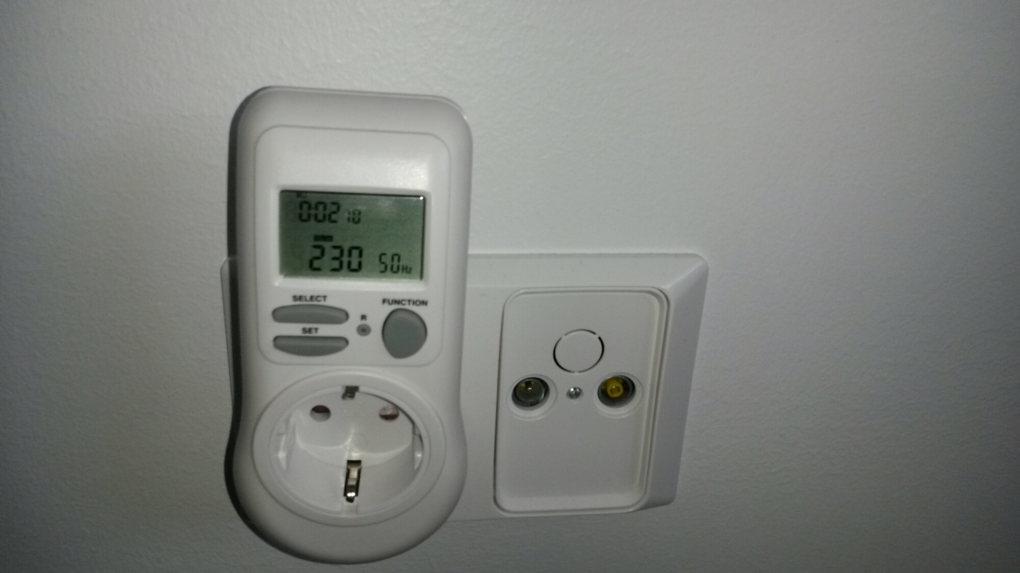
The answer is that you can do that. To do the measurement that reveals the loop impedance and the prospective short circuit current (PSCC) you need basically a voltage meter and a load that takes a known current from the mains power (current from few amperes to maximum outlet circuit rating should be OK). The idea is that you measure the voltage on your outlet without the load and with the load connected. Then you calculate the voltage drop cause by the load, and dividing it with the load current, you get the impedance. With this impedance and mains voltage, you can calculate the prospective short circuit current (PSCC).
I did this testing on normal electrical outlet in Finland. Here the nominal mains voltage is 230V AC, and the maximum current available from outlet is 10A or 16A (depending on the fuse size in the electrical panel).
For the masurements of the mains voltage (and load current) I used a pretty cheap meter designed to measure mains voltage, current, power and so on. This instrument was sold many years ago by Lidl (ENERGY SAVING TIMER model 9149 from year 2008).
Add 1 kW load
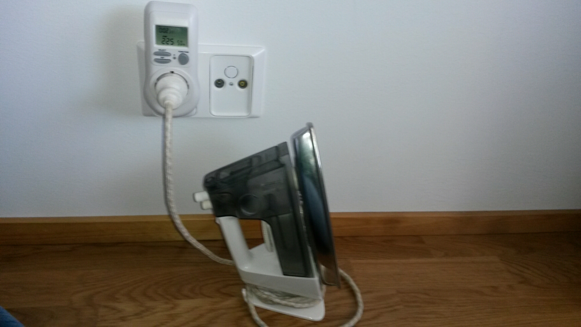
Results
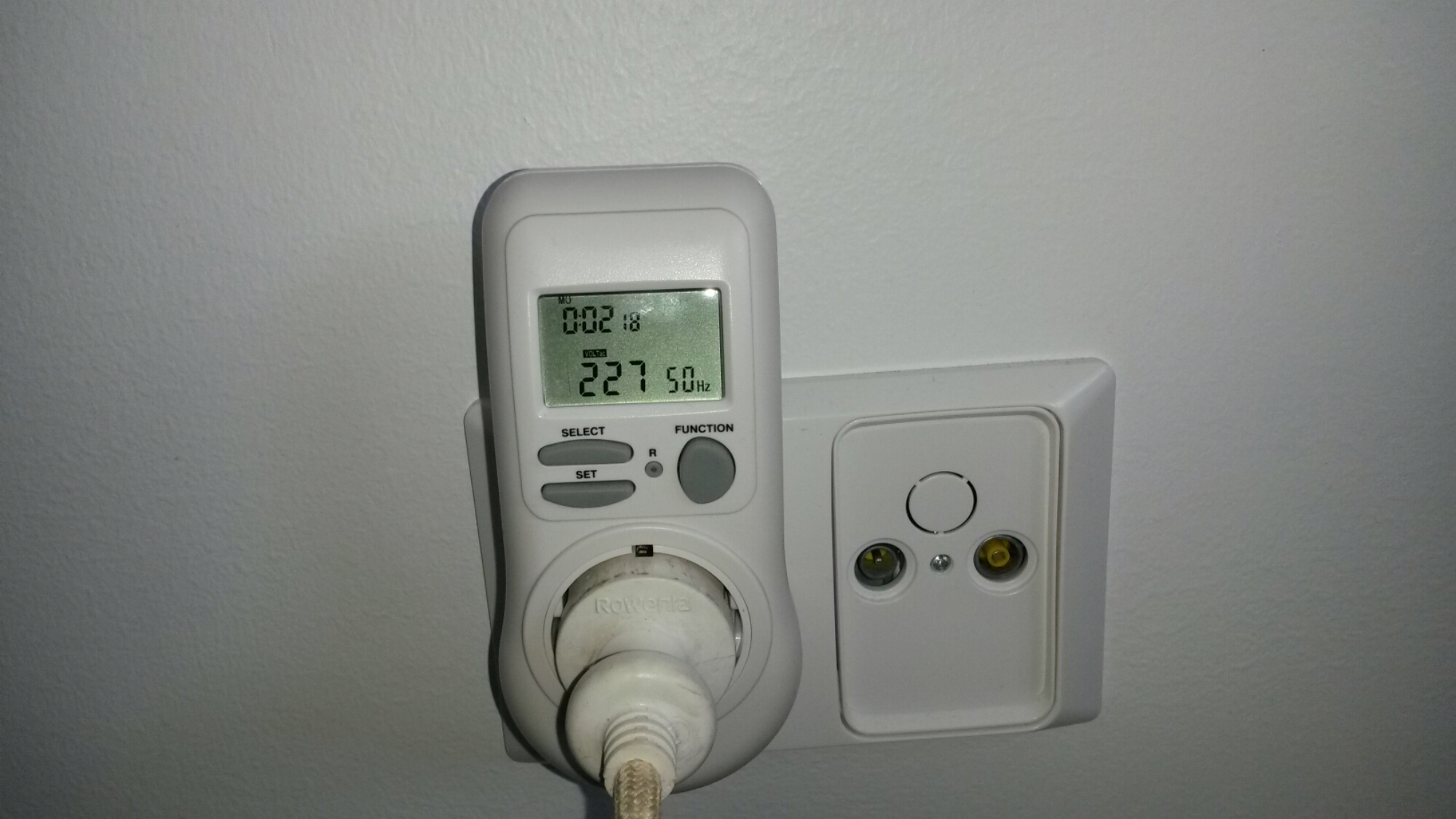
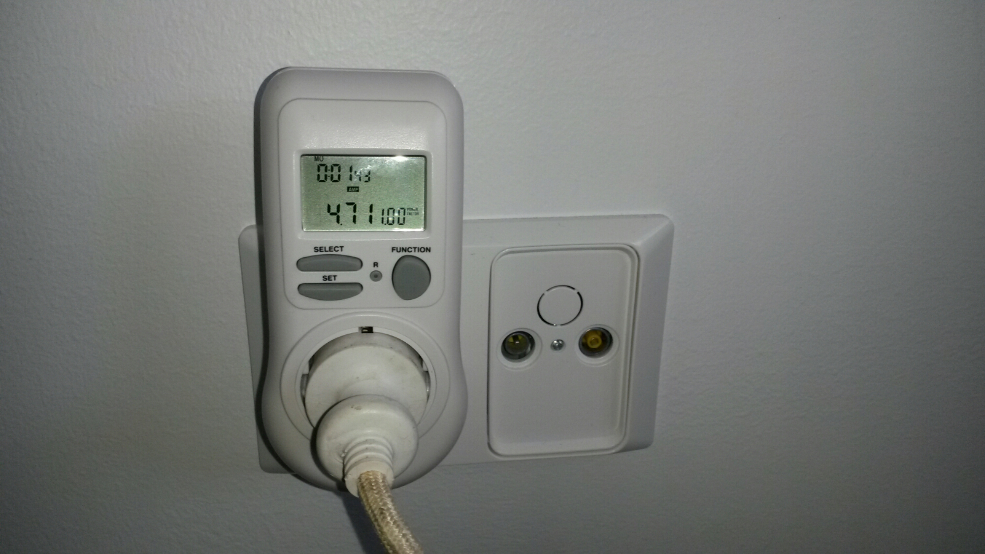
Result: voltage drop 3V at current 4.71A
Calculate loop impedance: 0.64 ohms
Maximum short circuit current: 359A
Sources:
Fluke: The importance of loop impedance testing
Wikipedia: Prospective short circuit current
Short Circuit Current of Circuit Breaker
Short Circuit Current Rating (SCCR)
UL: Panelboard and Switchboard Short Circuit Current Ratings
Ecmweb: Basic short-circuit current calculation
Calculating Short-Circuit Current
25 Comments
Tomi Engdahl says:
Breaking capacity
https://en.wikipedia.org/wiki/Breaking_capacity
Breaking capacity or interrupting rating[1] is the current that a fuse, circuit breaker, or other electrical apparatus is able to interrupt without being destroyed or causing an electric arc with unacceptable duration. The prospective short circuit current which can occur under short circuit conditions should not exceed the rated breaking capacity of the apparatus. Otherwise breaking of the current cannot be guaranteed.
Calculation of the required breaking capacity involves determining the supply impedance and voltage.
Miniature circuit breakers and fuses may be rated to interrupt as little as 85 amperes and are intended for supplementary protection of equipment, not the primary protection of a building wiring system.
In North American practice, approved general-purpose low-voltage fuses must interrupt at least 10,000 amperes
Tomi Engdahl says:
Loop Impedance
https://www.youtube.com/watch?v=HsWWKzjVUxE
Loop impedance, why it matters and typical values.
Tomi Engdahl says:
Voltage Drop in Electrical Circuits
https://www.youtube.com/watch?v=hPHLxi9qBH8
A demonstration and explanation of voltage drop in electrical installations.
Tomi Engdahl says:
Measuring earth-fault loop impedance and prospective short-circuit current
https://www.tlc-direct.co.uk/Book/8.6.2.htm
Tomi Engdahl says:
Voltage Drop in Electrical Circuits
https://www.youtube.com/watch?v=hPHLxi9qBH8
A demonstration and explanation of voltage drop in electrical installations.
Tomi Engdahl says:
Total Earth Fault Loop Impedance Zs = Ze + R1 + R2 for TN-S and TN-C-S Earthing Arrangements
https://www.youtube.com/watch?v=Ksg2zQLuiAs
Total Earth fault Loop Impedance for an installation connected to a TN-S and TN-C-S earthing arrangements: this video shows drawings to aid with City and Guilds and EAL electrical exams at level 1, 2 and 3.
Earthing Arrangements TN-C-S, TN-S and TT
https://www.youtube.com/watch?v=i22OiHyWeUg
Tomi Engdahl says:
Voltage Drop in Electrical Circuits
https://www.youtube.com/watch?v=hPHLxi9qBH8
Tomi Engdahl says:
Recap of TN-S Earthing Arrangements and Measuring External Earth Fault Loop Impedance Ze
https://www.youtube.com/watch?v=zgxrGoTMmDY
Recap training aid for correctly identifying a single phase installation earthing arrangements in this case TN-S. includes a size of tails and earthing conductor max Ze 0.8 vohms.
Tomi Engdahl says:
On-Site Changing an Outside LED Light Connected to a TT Supply (Read Description) Includes Testing
https://www.youtube.com/watch?v=Z1VW93u_5pU
Tomi Engdahl says:
Loop Impedance Testing
https://www.youtube.com/watch?v=79rT9SrWXrY
Methods of testing external loop impedance and prospective fault current.
Explanation of loop impedance:
Loop Impedance
https://www.youtube.com/watch?v=HsWWKzjVUxE
Tomi Engdahl says:
Earth Fault Loop Impedance Test & Prospective Fault Current Test
https://www.youtube.com/watch?v=_twVvsGo81A
Trade Skills 4U tutor Andy Summers talks you through earth fault loop impedance and prospective fault current testing. Please note this video is intended as a revision aid only.
Tomi Engdahl says:
Recap of TN-S Earthing Arrangements and Measuring External Earth Fault Loop Impedance Ze
https://www.youtube.com/watch?v=zgxrGoTMmDY
Sorry the sound isn’t as good as my later videos but all the points covered in this compilation are required during our installation theory exams thanks Gaz.
Recap training aid for correctly identifying a single phase installation earthing arrangements in this case TN-S. includes a size of tails and earthing conductor max Ze 0.8 vohms.
Videos are training aids for City and Guilds (C and G) and EAL courses Level 1, 2 and 3
Tomi Engdahl says:
Why clamp meter / tester for grounding?
https://electrical-engineering-portal.com/measure-ground-resistance-clamp-meter
The ground clamp meter / tester is an effective and time-saving tool when used correctly because the user does not have to disconnect the ground system to make a measurement or place probes in the ground.
The method is based on Ohm’s Law, where:
R (resistance) = V (voltage) / I (current)
The clamp includes a transmit coil, which applies the voltage and a receive coil, which measures the current. The instrument applies a known voltage to a complete circuit, measures the resulting current flow and calculates the resistance
Tomi Engdahl says:
Earth/ground measurement guide
http://www.chauvin-arnoux.com/sites/default/files/documents/dc_earth-ground_measurement_ed1.pdf
Tomi Engdahl says:
AC loop impedance testing
https://www.plantengineering.com/articles/ac-loop-impedance-testing/
Electrical safety testing isn’t just for the sake of bureaucratic compliance. It has practical implications that literally protect lives. Improvements in electronic instrumentation have gone a long way toward eliminating the perceived “nuisance factor” in such testing. A tragic instance of the failure to insure safety was reported in the IAEI News (International Association of Electrical Insp…
Tomi Engdahl says:
Voltage Drop in Electrical Circuits
https://www.youtube.com/watch?v=hPHLxi9qBH8
A demonstration and explanation of voltage drop in electrical installations.
The excessive volt drop shown in this video was caused by a fault with the supply, which was fixed shortly after this video was made.
Tomi Engdahl says:
Loop Impedance Testing
https://www.youtube.com/watch?v=79rT9SrWXrY
Methods of testing external loop impedance and prospective fault current.
Tomi Engdahl says:
LEARN ABOUT HOW EARTH FAULT LOOP IMPEDENCE TESTING IS DONE
https://carelabz.com/about-earth-fault-loop-impedence-test/
Tomi Engdahl says:
Socket & See SOK36 | Earth loop impedance test plug
https://www.youtube.com/watch?v=GQhaXfCleR0
The socket and see sok36 is a socket tester with a difference. Not only can it check that the socket is wired correctly, it can also check the earth loop impedance. The tester also has a polarity check and can also test the RCD is working correctly. The tester also has a built in self check.
Socket & See SOK36 Professional Socket Tester
https://www.amazon.co.uk/Socket-See-SOK36-Professional-Tester/dp/B01KL9X9T8
Tomi Engdahl says:
Martindale MAREZ150 Loop Check Plug tester-Yellow
https://www.amazon.co.uk/Martindale-MAREZ150-Loop-Check-tester-Yellow/dp/B002L651LY/ref=pd_day0_hl_328_4/257-7039794-7562026?_encoding=UTF8&pd_rd_i=B002L651LY&pd_rd_r=db9bcb39-9904-11e9-94c1-e74c64e5ee94&pd_rd_w=K2y2E&pd_rd_wg=56qJ1&pf_rd_p=92d624bb-a334-423e-8722-8024dd09667f&pf_rd_r=GGF5YJWJZ7D87Y66TPV5&psc=1&refRID=GGF5YJWJZ7D87Y66TPV5
This is the first socket tester that gives a measurement of the earth loop impedance. This is the only safe solution for socket testing, as other testers can indicate as safe a socket with a dangerously high earth resistance. Conventional indicators have the weakness that they only tell if the earth is connected, they don’t indicate how safe it is. Martindale’s new T-Safety patented technology gives safe, earth loop impedance checking within carefully selected bands without tripping the RCDs. Features: Non-trip earth loop test Voltage test Socket test for open termination and correct wires T-Safety patented technology Identifies faults other checkers can’t This unit is an indicator and is not designed to give readings for completing certificates.
Tomi Engdahl says:
https://www.repelec.com.au/socket-tester-earth-loop-polarity-rcd-check.html
The SOK32 povides clear indication of correct wiring plus 18 wiring fault conditions. The SOK36 in addition to the SOK32 functions performs a non trip earth loop impedance test & indicates the result as <1.5Ω, 2.5Ω. Additional selectable functions are available to check the tripping function of 30mA RCD’s and also a mains Active/Neutral polarity check.
Tomi Engdahl says:
What Does Available Fault Current Mean?
https://www.youtube.com/watch?v=7-zkAo1EtIM
What does the term Available Fault Current mean? It’s not a term we hear terribly frequently in the industry unless you are having to mark the panel you are installing, or you hear about it while studying for an exam. It is not as baffling or confusing as it may sound! In this episode of Electrician U, Dustin talks about what the term stands for and how it is used.
Tomi Engdahl says:
Earth Fault Loop Impedance
https://www.youtube.com/watch?v=GvQS8fK39yU
Earth Loop Impedance Test | Electrical Tutorial
https://www.youtube.com/watch?v=rMA0KycGgYY
Tomi Engdahl says:
Breaking Capacity of 5x20mm glass fuse is typically at 35 A – 200 A range, while the current that you can get at full short circuit from normal 230V mains outlet can be easily 400A or more.
Tomi Engdahl says:
https://elek.com/resources/free-electrical-calculators/fault-loop-impedance/