Sometimes there is need to measure power going to different devices. Measuring DC power consumption is pretty easy, but when you try to do the same for AC circuit, things start to become complicated. How to Measure Electrical Power article will discuss best practices for making electrical power measurements, starting with power measurement basics and proceeding to the types of instruments and associated components typically used to make measurements. DC power measurement is relatively simple as the equation is simply watts = volts x amps. For AC power measurement, the power factor (PF) introduces complexity as watts = volts x amps x PF. This measurement of AC power is referred to as active power, true power or real power. Power is typically measured with a digital power analyzer or a DSO (digital storage oscilloscope) with power-analysis firmware.
What if you want to implement power mesurement yourself? Power consumption in AC circuit is correctly measured by calculating volts x amps = volt-amps (apparent power) over time, using at least one complete cycle. Using digitizing techniques, the instantaneous voltage is multiplied by the instantaneous current then accumulated and integrated over a specific time period to provide a measurement. This method provides a true power measurement and true RMS measurements for any waveform up to the bandwidth of the instrument.
In addition to math, you will need to provide some sensors to measure current and voltage. For AC current measurements potential sensor types are shunt resistor, current transformer, hall current sensor and rogowski coil. Usually current transformer and hall current sensor are the most suitable types to use with Arduino (they both provide isolation from measurent circuit). For AC voltage measurements the most suitable sensor types are voltage transformer, capacitive voltage divider and resistive voltage divider. From those alternatives only voltage transformer can provide galvanic isolation from circit being measured.
Can this measurement of AC power made using Arduino? The answer is yes, ans there are several ways it can be done. AC Power Theory – Arduino maths web page provides inntroduction how this can be implemented with Arduino (check also Advanced maths). There is EmonLib library that provides you a set of ready made AC measurement calculation routines that you can use easily.
Arduino sketch – voltage and current from OpenEnergyMonitor project shows how you can do the AC power measurements with Arduino.
#include "EmonLib.h"              // Include Emon Library
EnergyMonitor emon1;              // Create an instance

void setup()
{
  Serial.begin(9600);

  emon1.voltage(2, 234.26, 1.7);  // Voltage: input pin, calibration, phase_shift
  emon1.current(1, 111.1);        // Current: input pin, calibration.
}

void loop()
{
  emon1.calcVI(20,2000);          // Calculate all. No.of crossings, time-out
  emon1.serialprint();            // Print out all variables
}
To us this simple looking source code, you need to have EmonLib installed (it does all the complex calculations so you don’t need to worry about them). The simplest way is to download EmonLib zip packet and extract it to arduino libraries folder. It will give the needed library and project examples.
Here is example code I used “voltage_and_current” (my modified version):
// EmonLibrary examples openenergymonitor.org, Licence GNU GPL V3
#include “EmonLib.h” // Include Emon Library
EnergyMonitor emon1; // Create an instance
void setup()
{
Serial.begin(9600);
emon1.voltage(2, 11.7 /* 234.26 */, 1 /* 1.7 */); // Voltage: input pin, calibration, phase_shift
emon1.current(1, 5.5 /* 111.1 */); // Current: input pin, calibration.
}
void loop()
{
emon1.calcVI(20,2000); // Calculate all. No.of half wavelengths (crossings), time-out
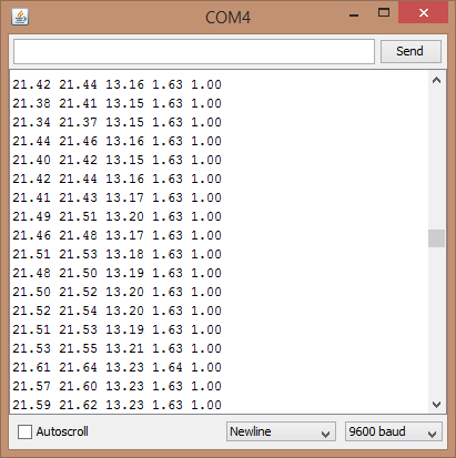
emon1.serialprint(); // Print out all variables (realpower, apparent power, Vrms, Irms, power factor)
float realPower = emon1.realPower; //extract Real Power into variable
float apparentPower = emon1.apparentPower; //extract Apparent Power into variable
float powerFActor = emon1.powerFactor; //extract Power Factor into Variable
float supplyVoltage = emon1.Vrms; //extract Vrms into Variable
float Irms = emon1.Irms; //extract Irms into Variable
}
I got the following output when I measured 20W halogen lamp system:
Here is picture of the Arduino Nano + Nano Sensor Shield based test circuit I used:

In this test circuit I measured 12V halogen lamp system current and voltage. For current mesurement I used ACS712 sensor based current measurement sensor module with +-5A current measurement range. For voltage measurement I used a simple voltage divider module (22k ohm from input pin to +5V, 22 kohms from input pin to ground, 120 kohms from AC voltage source to input pin).
One note in plannng to use this power measurements: If you plan to measure mains power, you need to understand all the safety details related to mains power. When testing the circuit, I highly recommend that you have a low voltage test system that you can sefely test and debug your designs (hardware and software). I have used 12V halogen lamp system for this: a traditional 12V transformer gives out safe 12V AC output usually at several amperes, you can control the load easily by turning 12V lamps on/off as needed. When you have debugged your design at safe voltages, you can start thinking of working with higher dangerlous voltages!
Related project pages:
OpenEnergyMonitor building blocks
Watt Meter build walks you through Power Measurement basics
Digital Data from a Cheap Power Meter
115 Comments
Tomi Engdahl says:
Interesting current sensor for DC applications for Arduino INA219B
https://learn.adafruit.com/downloads/pdf/adafruit-ina219-current-sensor-breakout.pdf
Tomi Engdahl says:
Self Built Power Meter Uses Dual Sense Transformers
http://hackaday.com/2015/08/08/self-built-power-meter-uses-dual-sense-transformers/
[Renaud] built a AC power meter from scratch. While commercial power meters like the Kill A Watt are available [Renaud’s] build gives an interesting insight into the methods used.
currentAt the heart of [Renaud’s] design lie two sense transformers. The first is a typical voltage stepdown transformer. This brings the AC line voltage down to +/- 10V, which is more amenable to digital sampling. The second is a current sense transformer
http://renaud.schleck.free.fr/wattmetre.php
Tomi Engdahl says:
Another mains power meter project:
WiFi Power Monitor
http://hackaday.com/2015/10/04/wifi-power-monitor/
Building your own hardware to measure AC power isn’t a simple task. There’s a number of things to measure, including voltage, current, power, and power factor. The Atmel 90E24 is a single chip solution designed for this exact purpose. Connect a few components, and all the power data is available to a microcontroller over SPI.
Aside from the Atmel 90E24 device, a high power and low resistance resistor is needed for shunt sense current measurement.
[hwstar] built a custom power monitoring board based on this IC. His AC-Emeter will give you all the measurements you’d want, and includes an ESP12 module for data collection and WiFi connectivity.
Hardware for an ESP8266 or Arduino based AC power meter using the Atmel 90E24 energy management chip
https://github.com/hwstar/HW-AC-Emeter
Tomi Engdahl says:
Energy monitor with Arduino
Measure energy consumption with Arduino
https://hackaday.io/project/8505-energy-monitor-with-arduino
Recently I discovered http://openenergymonitor.org/
It has all necessary information for building home energy monitor – software and hardware.
I have a few ideas for improvement.
Tomi Engdahl says:
Using low cost appliance energy meter for AC power measurements:
Energy Meter Hacking – Reading EOUT Pulses
http://steelcityelectronics.com/2015/08/02/energy-meter-hacking-reading-eout-pulses/
Tomi Engdahl says:
Finally, a Power Meter Without Nixies
http://hackaday.com/2016/01/22/finally-a-power-meter-without-nixies/
https://github.com/TSalwach/ICPA/wiki/Design-considerations
First steps lead me to OpenEnergyMonitor. I looked into https://github.com/openenergymonitor/EmonLib/blob/master/EmonLib.cpp
and found that is not something that I’m looking for.
it’s one phase only (3 phase = 3 Arduinos ~ still cheap for AVR based one but not so cheap for 12-bit resolution ARM based one )
Arduino’s way of using ADC’s is very slow – only about 50 I,V samples per mains cycle. They do some “weird” filtering to deal with that.
I wanted:
to collect all 3 phases currents and voltages simultaneously
to make AC waveform graphs
12-bit resolution
accuracy…as I plan to use only one device on whole home and like to see 1W difference on meter capable measuring some kWatts
reactive power with sign (indication of capacitive or inductive load)
to have frequency measurement like on MainsFrequency.com – read the story behind that
to have whole system in my home network – without need of internet connection and cloud storage
I love everything open and I wanted this project to be replicable, customizable and very simple
After some research starting at AC power I’ve found excellent application note: Texas Instruments SLAA577G – Implementation of a Three-Phase Electronic Watt-Hour Meter
Syed says:
how you get this calibration??
emon1.voltage(2, 234.26, 1.7); // Voltage: input pin, calibration, phase_shift
emon1.current(1, 111.1); // Current: input pin, calibration.
Syed says:
i am confused about calibrating voltage and current sensor??? i want to make pf meter to measure pf of loads such as bulb.
Kindly help
Tomi Engdahl says:
I did the calibration on one of my protoype using the following method:
I had 12V halogen 20W lamp that used traditional transformer (gave out 50 Hz AC).
I connected the Arduino board plus to multimeters (one for current and other for voltage).
Then I looked at what the Arduino showed and what the multimeter showed. For example if the voltage Arduino showed was for example around twice what it should be, I adjusted the cablibration values according to the difference (in this case multiplier should be either twice or half of the original value depending how it is used, I don’t remember, but easy to test which is right direction).. Do the same for current.
For phase shift, use the data from the current transformer data sheet.
suleman says:
Are u done it???
Tomi Engdahl says:
What do you mean?
Talha says:
emon1.calcVI(20,2000);
What it is for? why 20 and 2000
Tomi Engdahl says:
The first parameter (20) defines over how long time period the calculation is performed. Here the value 20 means over 20 zere crossings (=10 AC cycles).
The second parameter (2000) is some kind of timeout to stop analyzing if it takes more than reasonable amount of time.
Thien says:
20 means sample. My code on 1 second: emon1.calcVI(2000,1000); // Calculate all. No.of half wavelengths (crossings), time-out
Akpellas says:
First of all, I’m not an energy expert, but I would like to explain two concepts that I think are misunderstood.
The EmonLib library is designed to measure 3-phase electric power , so uses the factor (sqrt root) 3 = 1.732050 (380V), but when you want to measure 1-phase electric power, the factor is (sqrt root) 2 = 1.414213 (230V), in this case must be replace value 1.7 –> 1.41 in the formula
emon1.voltage (2, 234.26, 1.41); // Voltage: input pin, calibration, phase_shift.
About Power factor,this value is provided by the company that builds motors, which writes on specifications plate, and shows how many energy transforms in job, always this value is between 0.80 to 0.85, never will be over 1. In 1-phase electric power isn’t need power factor, due Electrical appliances consume low energy.
Thien says:
Thank’s about your comments!
emon1.voltage(0, 240.074, PhaseV); // Voltage: input pin, calibration, phase_shift
Where: PhaseV = 1.41; adaptor Power 220/9 therefore calibration = 240.074
nabin bera says:
I’m using 230/2 volt PT and 5/1 amp 15 VA CT to step down voltage and current respectively.and using two 8.2 ohms 2watt resistor in series across CT to get voltage drop corresponding current.this two parameters are fed to arduino analog pin A0 and A1 .so what will be the calibration values and phase sift emonlb.h related program.
Here is the program
#include “EmonLib.h” // Include Emon Library
EnergyMonitor emon1; // Create an instance
void setup()
{
Serial.begin(9600);
emon1.voltage(2, 234.26, 1.7); // Voltage: input pin, calibration, phase_shift
emon1.current(1, 111.1); // Current: input pin, calibration.
}
void loop()
{
emon1.calcVI(20,2000); // Calculate all. No.of crossings, time-out
emon1.serialprint(); // Print out all variables
}
Tomi Engdahl says:
Here are some articles with calibration advice:
https://openenergymonitor.org/emon/buildingblocks/ct-and-ac-power-adaptor-installation-and-calibration-theory
https://openenergymonitor.org/emon/buildingblocks/calibration
Tomi Engdahl says:
Put a Reverse Engineered Power Meter in Your Toolkit
http://hackaday.com/2016/07/11/put-a-reverse-engineered-power-meter-in-your-toolkit/
It seems that one can buy cheap power meters online and, well, that’s it. They work just fine, but to use them for anything else (like datalogging or control or…) they need a bit more work. The good news is that [Thomas Scherrer], alias [OZ2CPU], just did that reverse engineering work for us.
Inside these budget power meters, you’ll find an LCD driver, a power-monitoring chip, and an STM32F030, which is a low-cost ARM Cortex M0 chip that’s fun to play with on its own. [Thomas] traced out the SPI lines that the power-monitoring chip uses to talk to the microcontroller and broke in to snoop on the signals. Once he got an understanding of all the data, tossing an ATmega88 chip on the SPI line lets him exfiltrate it over a convenient asynchronous serial interface.
Peacefair pzem-021 energy meter hacked SPI to SERIAL out AVR mega 88
http://webx.dk/oz2cpu/energy-meter/energy-meter.htm
The Peacefair PZEM-021 energy meter is very popular and super cheap at ebay
the unit is very good and usefull for all sorts of projects and to be used when working with mains powered electronics.
Tomi Engdahl says:
Root Mean Square
http://hackaday.com/2016/08/04/root-mean-square/
Meters
You can compute RMS voltage using an oscilloscope. However, with a meter, it can be tricky depending on what the meter measures. Most meters that don’t claim to measure RMS, read the average value of the voltage. Some meters measure RMS but only for a sine wave. Older true-RMS meters used thermal or electrodynamic methods to measure the RMS value. However, modern meters are usually adept at measuring RMS, at least for pure AC signals. A very few meters will have an option to measure RMS voltage for signals with a DC component, like an offset.
According to Fluke, an average-reading meter will read 10% high on a square wave, 40% low on the output of a single-phase diode rectifier, and anywhere from 5% to 30% low on the output of a three-phase diode rectifier. Big difference.
Mohit yadav says:
How can measure ac power for variable load.
Suppose 2 load is on for “t” sec then, 1 load aaded or removed form it how can we measure power now.
Which type of sensors we should use. To measure current and voltage.
Tomi Engdahl says:
> Which type of sensors we should use. To measure current and voltage.
When you measure mains power with your own electronics for safety reasons you should use sensors that provide isolation between dangerous mains voltages and Arduino (commercial mains power measurement devices packed to well insulated case can be built without isolation).
For voltage measurement a transformer isolation is a good idea, for example 230V AC to 12V AC mains transformer followed with suitable resistive voltage divider has proven to work. Other transformer output voltages are suitable down to few volts.
For current measurement a current transformer. I have for example used this:
http://www.epanorama.net/newepa/2014/10/21/stc-013-20-current-transformer/
Hall sensor can also be used to measure AC current:
http://www.epanorama.net/newepa/2014/02/28/meeeno-acs712-current-measuring-sensor/
Tomi Engdahl says:
Measuring AC power with the Industruino PROTO
http://www.epanorama.net/newepa/2016/11/21/measuring-ac-power-with-the-industruino-proto/
Tomi Engdahl says:
Decabit: Or The Conspiracy Theory That Wasn’t
http://hackaday.com/2016/12/06/decabit-or-the-conspiracy-theory-that-wasnt/
[LDX] first noticed the odd sounds coming out of his ceiling fan, regularly, on the hour and half-hour. Then he noticed that the lights were flickering as well. Figuring something was up, he built a logging power-line monitor to see if he could decode the shadowy signals and figure out what cryptic messages were being transmitted over the power lines. Naturally, he suspected the Illuminati were behind it.
Even if you’re not prone to flights of fancy, you might want to keep track of your power line because it can serve as an accurate long-run timebase for projects, or because it can tell you something about the overall health of the grid.
Investigating AC
Get your tinfoil hat ready!
https://hackaday.io/project/18619-investigating-ac
I used a Teensy 3.1 running at 96MHz connected to a voltage divider circuit from a 10v AC adapter, the waveform is shifted up above 0v to capture the full wave.
The code averages 2 readings before pushing to serial port, use the ‘Serial Plotter’ function
to view the wave (it is really fast but screenshot-able).
Tomi Engdahl says:
Mains Frequency Display
http://hackaday.com/2013/12/12/mains-frequency-display/
Tomi Engdahl says:
How to Trick Your Electrical Meter By Saving Power
http://hackaday.com/2017/04/04/how-to-trick-your-electrical-meter-by-saving-power/
A group of Dutch scientists have been testing out some of today’s “smart” electrical meters to check their accuracy, among other things. Not ones to disappoint, the scientists have found consistently false readings that in some cases are 582% higher than actual energy consumption.
Their results? Well, “results varied wildly, with some meters reporting errors way above their disclosed range, going from -32% to +582%. Tests with uncommon results were repeated several times
Millions of Smart Meters May Over-Inflate Readings by up to 600%
https://www.bleepingcomputer.com/news/hardware/millions-of-smart-meters-may-over-inflate-readings-by-up-to-600-percent/
Lab tests carried out by Dutch scientists have shown that some of today’s “smart” electrical meters may give out false readings that in some cases can be 582% higher than actual energy consumption.
The study involved several tests conducted on nine different brands of “smart” meters, also referred to in the industry as “static energy meters.” Researchers also used one electromechanical meter for reference.
Using a simple test rig, portrayed above, researchers connected the smart meters to various power-consuming appliances found in regular homes, such as energy saving light bulbs, heaters, LED bulbs, and dimmers.
Problems blamed on smart meter designs
Researchers blamed all the issues on the design of some smart meters, and, ironically, electrical devices with energy-saving features.
The latter devices, researchers say, introduced a large amount of noise in electrical current waveforms, which disrupt the smart meter sensors tasked with recording power consumption.
“The reason for faulty readings appears to be the current sensor,
and the associated circuitry,”
Since the research only covered smart meters commonly installed in Dutch homes, researchers say that around 750,000 smart meters deployed around the Netherlands may be giving out false readings.
Worldwide, the numbers of possibly faulty smart meters could be in the millions, especially after some governments, especially in the EU, have pushed for smart meters to replace classic electromechanical (rotating disk) meters.
UPDATE [March 27, 2017]: ESMIG, which describes itself as |the European voice of the providers of smart energy solutions” has published research that disputes the findings of the Dutch researchers. Here are their main conclusions :
The electromagnetic interference phenomena created in the tests of the University of Twente grossly exceed emissions limits allowable under EU regulation for equipment typically used in households.
These conditions would not be found in any imaginable normal household scenario.
There is no reason to question smart metering technology.
Tomi Engdahl says:
How Many Watts Are You Using?
http://hackaday.com/2017/04/22/how-many-watts-are-you-using/
[Bogdan] built up a simple whole-apartment power monitor from scratch over the weekend, and he’s been nice enough to walk us through the whole procedure, starting with picking up a split-core CT sensor and ending up with a finished project.
The brains of his project are an ESP8266 module, which means that he needed to adapt the CT sensor to put out a voltage that lies within the chip’s ADC range of 0 V to 3.3 V.
The microcontroller reads the ADC frequently, does a little math, and you’re done.
The rest of the code was borrowed from here or there. EmonLib takes care of the math, ArduinoOTA allows him to reflash the firmware over the air, and Blynk takes care of making a nice Android app for visualization.
Power meter for the entire apartment
http://bogdan.nimblex.net/diy/2017/04/19/apartment-energy-monitor.html
Tomi Engdahl says:
How to Measure Electrical Power
http://www.edn.com/design/test-and-measurement/4392053/How-to-Measure-Electrical-Power
If a product uses power, then power consumption and power quality measurements must be made as part of product design and test. These measurements are essential to optimize product design, comply with standards and provide nameplate information to customers.
This article will discuss best practices for making these measurements, starting with power measurement basics and proceeding to the types of instruments and associated components typically used to make measurements.
Tomi Engdahl says:
Review: SmartPi – smart meter extension for Raspberry Pi
https://www.elektormagazine.com/news/review-smartpi-smart-meter-extension-for-raspberry-pi
What is the SmartPi?
The SmartPi is an extension board to turn a Raspberry Pi into a smart energy meter. All the parts, including the enclosure, are available separately but it is also possible to buy a fully assembled device (discussed here). The assembled version is built on a Raspberry Pi 3 model B.
The SmartPi can measure current (up to 100 A, with a hardware modification up to 300 A is possible), voltage (up to 400 V) and frequency on three phases plus neutral and calculate several flavors of power (active, reactive & apparent) and consumption.
The software is open source and available from GitHub.
The evaluation SmartPi came with three current sensors.
The web interface showed three currents, three voltages and three frequencies.
Conclusion
The SmartPi is a Raspberry Pi extension board for makers, not a consumer product. The software supporting it is basic — three-phase only, configuration over SSH —, documentation is insufficient. People without RPi or Linux experience will be lost quickly.
On the other hand, if you are looking for a platform on which to build yourself a smart energy consumption metering system, the SmartPi definitely is a good start.
Tomi Engdahl says:
Nabito Is an Open Meter for EV Charging
https://blog.hackster.io/nabito-is-an-open-power-meter-for-ev-charging-d221093d26e8
As electric vehicles become more popular, one problem is where to charge them.
In order to provide a charging and billing method for these spaces, Systems Distributed has come up with Nabito — the Open Socket.
The device is powered by an OrangePi single-board computer, and users are pointed to a web interface where they can interact with it via a QR code. Additionally, an Arduino Uno with a current sensor is used to measure power supplied, and a relay switches the outlet on or off.
Though there are commercial charging options available, this project was implemented for around $60, potentially making this type of metered charging more accessible.
Nabito – the Open Socket: Smart Meter for EV Charging
http://www.instructables.com/id/Nabito-the-Open-Socket-Cheap-Smart-Meter-for-EV-Ch/
Tomi Engdahl says:
Dr. Wattson Energy Monitoring Board
https://blog.hackster.io/dr-wattson-energy-monitoring-board-8b5b6fb6a23a
The breakout board is equipped with a Microchip MCP39F521 chip to measure the power used on a single outlet. It features an Arduino library to facilitate use with this and similar dev boards, meaning your custom monitoring or even control solution is only a few steps away.
Tomi Engdahl says:
Dr. Wattson
http://upbeatlabs-wattson.launchrock.com
Tomi Engdahl says:
Real-Time Energy Monitor with Arduino and LabVIEW
https://www.open-electronics.org/real-time-energy-monitor-with-arduino-and-labview/
This is a simple power meter to analize the current consuming in a house using the led indicator of a house energy meter.
Reading the red led of a home energy counters the system detects the corrent consumption in a house.
It is a noninvasive method
The system consists of two parts: the Arduino board that detects the led pulses and sends the data via the XBee module, and a PC that recive the data through a USB/Xbee module and processes the data with LabVIEW so you can prepare and study the consumption in a very instant.
Arduino sends two datas to the PC:
1 – Real time datas
2 – Average consumption measured in a time of 5 minutes.
Tomi Engdahl says:
https://openenergymonitor.org
Tomi Engdahl says:
Grid-2-Audio
https://hackaday.io/project/79848-grid-2-audio
A convenient adapter to view the electrical grid waveform through your PC’s sound card.
There is a lot to be observed from the waveform of the electrical mains. Harmonics, transient changes, periodic fluctuations, frequency shifts, impedance, power line communications – These all give clues as to the state of the country’s electrical transmission system (or what loads your neighbour has connected). Platforms like MATLAB allow for the easy analysis of waveforms through powerful software tools, but only once the signal has been acquired.
The purpose of this project is to allow easy and safe access to the electrical grid waveform without a hassle. It’s as simple as power cable in and 3.5mm audio out.
Tomi Engdahl says:
HomeEnergy – Pi
https://www.hackster.io/michael-nigbor/homeenergy-pi-cecfdf
Turn a Raspberry Pi into a home energy monitor with inexpensive components.
Tomi Engdahl says:
Smart Outlet Cover Offers Lessons on Going from Project to Product
https://hackaday.com/2018/04/25/smart-outlet-cover-offers-lessons-on-going-from-project-to-product/
Going from idea to one-off widget is one thing; engineering the widget into a marketable product is quite another. So sometimes it’s instructive to take an in-depth look at a project that was designed from the get-go to be a consumer product, like this power indicating wall outlet cover plate. The fact that it’s a pretty cool project helps too.
Although [Vitaliy] has been working on this project for a while, he only recently tipped us off to it, and we’re glad he did because there’s a lot to learn here. His goal was to build a replacement cover for a standard North American power outlet that indicates how much power is being used by whatever is plugged into it.
Energy and power indication inside the space of standard outlet cover
http://smartoutletcover.blogspot.fi/2017/11/energy-and-power-indication-inside.html
Main Function
Provide non intrusive way to sense total outlet current and process it for visual indication of:
power usage and energy usage (this prototype measured apparent power rather than real power)
Relative accuracy throughout the large range of measurements from ~21mA which is about 2.5W smallest cell phone charger to 13A or 1560W aprox max allowed power draw from outlet.
IoT connectivity and data processing
This was not implemented in this version but something I was thinking of in the future if prototype worked. There’re lots low cost, IoT MCUs on the market today that can be used for this purpose. But the first objective was to see if reliable sensing will be possible.
Taking apart one of the outlets to see where the best, non intrusive place to sense the current could be, I noticed that the center mounting bracket is ferromagnetic in nature and serves as a conductor (concentrator) of the magnetic flux flowing through the center of the two prongs of the plugs when current flows. As long as this magnetic circuit is not short circuited during installation it could be used for sensing.
One idea was to build a the current transformer using the plug’s prongs as a single loop primary and using mounting bracket as a magnetic core.
However, that idea was short lived. The number of turns of the primary coil needed was making the coil too large even with the smallest wire diameter.
The least cost in parts, assembly labor and size seem to be placing two small magnetic pick up coils positioned at the opposite sides of the center mounting bracket to pick up the magnetic field generated from the current in the plug(s). The small profile, high inductance, off the shelf coils are also readily available.
Symmetrical positioning of sensors allowed consistency in current measurement from upper and lower outlet.
The coils used were off the shelf throughole parts, 100mH each, B82144A2107J.
Some specs for the power supply: to drop down the AC line voltage to the 3.3V to power circuits, has to be small enough to fit into thin space, safe enough not to overheat or start fire especially in the event of voltage spikes or lighting transients and component failures, be reliable enough to supply fixed and clean voltage to the sensitive circuits like microcountroller. Power supply must also be of little cost, which relates to simplicity.
ATMEGA328PB is a low cost 8 bit, 16Mhz processor that has all the core functions needed for this design with 8 multiplexed 10 bits ADC inputs. The very first prototype I had was done using Arduino Mini that uses this processor. In order to drop the power usage to minimum the processor speed is set at 8 Mhz max speed (~38% less power than 16Mhz) it was more than enough to do the job. All other processor internal modules were shut off to save power.
Software
The software IDE I used was MisualMicro plugin for the MS Visual Studio. It’s free to use and has much better environment for codding than arduino IDE. Microprocessor performs all the work in sampling, converting and displaying power/energy usage. In first version of software, processor measures the apparent power by simply computing RMS of the current and multiplying it by RMS of the voltage (fixed constant).
Manufacturing Cost Estimates
The goal was to try to find most “bare bones” design that will adequately satisfy the requirements at the lowest component cost and count. With the current design there’s still room to reduce the cost by for example getting rid of crystal (~$0.71) and by using internal RC for clock generation, although with degradation in timing accuracy.
PWB assembly only:
Component BOM cost (based on digikey/mouser pricing): $10.1/ea Qnty 1000 (~$21 Qnty 10)
Bare PWB cost: <$0.20/ea Qnty 1000
Assembly of PWB cost: $1.3/ea Qnty 1000
TOTAL: $11.6/CCA
Mechanical assembly (qnty 1000):
Outlet plastic cover injection molded with holes and studs for CCA mount: $0.80
Contacts and misc assemlyl parts: $0.10
TOTAL: $0.9/Parts
Known problems
One major limitation of this sensing approach is that since magnetic circuit is not closed, it's naturally will be susceptible to external interference. In this case the accuracy seem to suffer if the outlet is not the last on the wiring branch.
The sensors, even positioned to sense magnetic flux deferentially, are still appear to be susceptible to the stray fields to the point where reading are off by more than 30% depending on the current even more
The other limitation is the interference caused by "wall wart" type of adapters (e.g. cell phone chargers).
Tomi Engdahl says:
Commercial meter
https://www.egauge.net/
Three-Phase Installation Tutorial
https://www.youtube.com/watch?v=EFikTPK045o
Three-phase installation tutorial for the eGauge EG3000 energy meter. This video explains the basics of installing the EG3000 in a three-phase distribution panel, defines each incoming line-voltage and shows how to connect the meter to a three-phase breaker.
Tomi Engdahl says:
Listening To Mains Power
https://hackaday.com/2018/08/23/listening-to-mains-power/
There’s a lot you can learn by looking at the waveform coming out of your outlets, but how do you tap into that? [David] is doing it with a PC sound card and some really interesting hardware.
The Grid 2 Audio module is [David]’s entry to this year’s Hackaday Prize, and it consists of three main parts. The first is the mechanical part of the design. This comes in the form of an IEC power socket with a built-in switch, fuse, and illumination.
The second part of this build is the PCB power supply and mains input. This is basically a pair of transformers, a PCB, and a whole lot of isolation to make this a safe board. The third part is a signal conditioning board that sends the waveform to a 3.5mm jack, for easy processing with any audio capture hardware.
The hardest part of this board is, by far, the PCB design, and for that [David] went all out. There are some big, meaty traces on this thing and real separation between the high voltage and low voltage portions of the board.
Grid-2-Audio
https://hackaday.io/project/79848-grid-2-audio
A convenient adapter to view the electrical grid waveform through your PC’s sound card.
There is a lot to be observed from the waveform of the electrical mains. Harmonics, transient changes, periodic fluctuations, frequency shifts, impedance, power line communications – These all give clues as to the state of the country’s electrical transmission system (or what loads your neighbour has connected). Platforms like MATLAB allow for the easy analysis of waveforms through powerful software tools, but only once the signal has been acquired.
The purpose of this project is to allow easy and safe access to the electrical grid waveform without a hassle. It’s as simple as power cable in and 3.5mm audio out.
Tomi Engdahl says:
Monitoring Power By Counting Blinks
https://hackaday.com/2018/09/05/monitoring-power-by-counting-blinks/
What do you do when you want to add a new feature to some electronics but you can’t or don’t want to tear into the guts? You look for something external with which you can interface. We like these hacks because they take some thinking outside the box, literally and figuratively, and often involve an Aha! moment.
[Simon Aubury’s] big household load was electric heating and his ancient heaters didn’t provide any way to monitor their usage. His power meters weren’t smart meters and he didn’t want to open them up. But the power meters did have an external LED which blinked each time 1 Wh was consumed. Aha! He could monitor the blinks.
Doing so was simple enough. Just point photoresistors at the two meter’s LEDs and connect them and capacitors to a Raspberry Pi’s GPIO pins. Every time a pulse is detected, his Python code increments the LED’s counter and every fifteen minutes he writes the counters to an SQL database.
Home Power Monitoring using a Raspberry Pi.
https://medium.com/@simon.aubury/home-power-monitoring-65d0fded7769
Tomi Engdahl says:
Chapter 20: Components and methods for current measurement
https://www.powerelectronics.com/power-management/chapter-20-components-and-methods-current-measurement?NL=ED-003&Issue=ED-003_20180914_ED-003_640&sfvc4enews=42&cl=article_2_b&utm_rid=CPG05000002750211&utm_campaign=19953&utm_medium=email&elq2=1f3c7edb844b46aaa9ea9a7f03774644
Current measurement components and methods must provide an accurate output signal as well as preventing damage to the associated printed circuit board.
Current sensing is used to perform two essential circuit functions. First, it is used to measure “how much” current is flowing in a circuit, which may be used to make decisions about turning off peripheral loads to conserve power or to return operation to normal limits.
Tomi Engdahl says:
Grid-2-Audio
https://hackaday.io/project/79848-grid-2-audio
A convenient adapter to view the electrical grid waveform through your PC’s sound card.
BS says:
Hi,
I am using ZMCT103C 5A Range Single Phase AC Active Output Onboard Precision Micro Current Transformer Module Current Sensor For Arduino. I tried different calibration values for current measurement, but it is not giving correct reading, it is not linear. If I adjust calibration value for with 4A load it is showing correct but when I reduce load for 2A it is not giving correct measurement, it shows more than 2.25A.
Can anyone please suggest solution for ZMCT103C Active Output module.
Tomi Engdahl says:
Strange.
I have no personal experience with ZMCT103C so it is hard to say where is the problem and what to do.
First it would be a good idea to measure with some known good instrument and different currents that ZMCT103C works as intended and works acceptably linearly (taking into account possibility that there is some manufacturing or design issue with that module).
BS says:
Thanks Tomi Engdahl
ZMCT103C module hasn’t work with Emon Library, I removed CT from this module and built new circuit with this CT (burden resistance 100 Ohm) and it is working perfectly with emon1.current(1, 90.0)
Tomi Engdahl says:
Wattmeter (simple AC power meter)
http://danyk.cz/wmetr_en.html
decided to use a specialized integrated circuit AD633 (AD633JN in classical THT case DIP8) – a four-quadrant analog multiplier with differential inputs and precision of 2%.
Simple Wattmeter circuit: Fig. 1 is the simplest power meter (wattmeter) design with the AD633 and a single range. The current is sensed by a shunt. If we require the output signal conversion 1mV/1W, the value of the shunt should be 0R4 (0.4 ohm). Maximum RMS current through meter is determined by the maximum allowable shunt power dissipation. For 0.4 ohm 40W shunt the max continuous current is 10A. Maximum measured power is 2300W for ideal resistive load, for different loads it must be lower. Another limitation is the maximum input voltage of multiplier (10V), so the maximum peak current must be below 25A.
Tomi Engdahl says:
The Most Expensive Way to Steal Music
https://www.youtube.com/watch?v=QDwN41Px_sY
Today, we’re finding out if you can cast a playable record out of resin!
Tomi Engdahl says:
Monitor Your Energy Bills via Modbus
https://www.hackster.io/123325/monitor-your-energy-bills-via-modbus-814e5e
Connect a Modbus energy meter to an Arduino and monitor power consumption via Home Assistant.
Tomi Engdahl says:
Energy Data Logger © CC BY-SA
https://create.arduino.cc/projecthub/javidambra/energy-data-logger-3e2dba
Simple data logger that stores electrical data (voltage, current, power, energy, etc.) in an SD card, with timestamp for later analysis.
Tomi Engdahl says:
Design and evaluation of
sampling, digital processing and
networking abilities of new
energy-sensing platforms
http://fse.studenttheses.ub.rug.nl/12871/1/thesis.pdf
Tomi Engdahl says:
High Voltage Measurement is Shockingly Safe
https://hackaday.com/2018/11/17/high-voltage-measurement-is-shockingly-safe/
With the right equipment and training, it’s possible to safely work on energized power lines in the 500 kV range with bare hands. Most of us, though, don’t have the right equipment or training, and should take great care when working with any appreciable amount of voltage. If you want to safely measure even the voltages of the wiring in your house there’s still substantial danger, and you’ll want to take some precautions like using isolated amplifiers.
Performing safer AC line voltage measurements using isolated amplifiers
https://ripitapart.com/2018/11/13/performing-safer-ac-line-voltage-measurements-using-isolated-amplifiers/
Tomi Engdahl says:
Monitor Home Energy Use with CircuitSetup’s Split Single Phase Energy Meter
https://blog.hackster.io/monitor-home-energy-use-with-circuitsetups-split-single-phase-energy-meter-1718b9d683fb
CircuitSetup’s Split Single Phase Energy Meter allows you to monitor the energy use in your entire home in real-time, which would let you calculate how much money is being spent, and find any appliance that may be drawing too much power.
The Split Single Phase Energy Meter features a Microchip ATM90E32AS, samples two current channels and one voltage channel, and can be paired with an ESP32/8266 for wireless monitoring
Tomi Engdahl says:
How to Build an Arduino Energy Monitor and Data Logger © GPL3+
https://create.arduino.cc/projecthub/sridhar-rajagopal/how-to-build-an-arduino-energy-monitor-and-data-logger-3bf795
How I built an Arduino energy monitor and data logger to collect energy data for different loads and plotted that data using Excel.
Tomi Engdahl says:
Monitor Home Energy Use with CircuitSetup’s Split Single Phase Energy Meter
https://blog.hackster.io/monitor-home-energy-use-with-circuitsetups-split-single-phase-energy-meter-1718b9d683fb
Tomi Engdahl says:
Power Measurement Oscilloscope Style
https://hackaday.com/2019/04/24/power-measurement-oscilloscope-style/
Truth is, an oscilloscope can measure almost anything if you know how. [Jim] shows how to measure the voltage and current in a circuit and then it is simply a matter of doing a little math, something modern scopes can do very easily.
Electronics can be pretty abstract and the oscilloscope is probably the best tool for visualizing what’s going on inside.
Tomi Engdahl says:
Phase Shift Detection Saves Pool Pump From Running Dry
https://blog.hackster.io/phase-shift-detection-saves-pool-pump-from-running-dry-a2dfb57cb51a
Luc Brun built a pump monitoring solution that is able to detect the phase shift between voltage and current, stopping the pump if the water level is too low.
system that keeps an eye on the voltage and current levels to the pump using an Arduino Nano and an ACS712 current sensor module, then measures the offset between the two. For a pump in normal operation, the phase shift will be 25°, while if the pump is running on empty, the shift between the two will be 45°.
Tomi Engdahl says:
Monitor Your Energy Bill via Modbus, MKR WiFi 1010 and RS485
https://create.arduino.cc/projecthub/123325/monitor-your-energy-bill-via-modbus-mkr-wifi-1010-and-rs485-814e5e
Connect a Modbus energy meter to an Arduino and monitor power consumption via Home Assistant.
Tomi Engdahl says:
A Non-Invasive ESP32 Energy Monitor
https://blog.hackster.io/a-non-invasive-esp32-energy-monitor-cae066cde600
uses a CT (current transformer) that clips onto a main power line to read current usage, and requires no direct electrical modifications.
This voltage signal is fed into an ESP32 module that controls the device, and pushes it to the AWS cloud over WiFi. From here, Savjee created a custom app to visualize his usage, which can show nearly instantaneous readings and graphs things nicely over time
DIY Home Energy Monitor: ESP32 + CT Sensors + Emonlib
https://savjee.be/2019/07/Home-Energy-Monitor-ESP32-CT-Sensor-Emonlib/
The ESP32 is a no-brainer for me because I’ve used it before on small projects. They are small, are easy to program (Arduino compatible), have a lot of power (160MHz dual-core processor, 520K memory) and have built-in WiFi which means they can directly connect to the internet. No hubs needed.
I went for the YHDC SCT-013-030 which can measure up to 30 amps of current (almost 7000 watts). More than sufficient for my small apartment. This model will output a voltage between 0 and 1, which is easy to measure using the built-in ADC of the ESP32.
JZ says:
Hello, can I please get an explanation of how the calibration and phase_shift is calculated?
emon1.voltage(2, 234.26, 1.7); // Voltage: input pin, calibration, phase_shift
Tomi Engdahl says:
Calibration information from
https://community.openenergymonitor.org/t/calibration-and-parameters-in-emonlib/6855
“234.26” is the mains voltage that gives you 1 V at the ADC input.
“111.1” is the mains current that gives you 1 V at the ADC input.
To calculate those, you must work backwards from the ADC input through the various resistors and transformers to the mains circuit.
“1.7” is the correction for the phase errors in the transformers and the timing error between sampling voltage and current. It’s hard to calculate, it is best to set it on test as explained on the calibration pages in “Learn”.
https://learn.openenergymonitor.org/electricity-monitoring/ctac/ct-and-ac-power-adaptor-installation-and-calibration-theory
Tomi Engdahl says:
https://learn.openenergymonitor.org/electricity-monitoring/ctac/calibration