I have testes several logic analyzers (both commercial and DIY) and software for them. I would like to see on this Open Source world is some kind of common format logic analyzer data presentation and maybe common API for accessing the information. In this way it would be easy to write all kinds of applications that decode data and hardware that captures the data independently. I would want something like what Wireshark did for network traffic analyzing – open source and easily expandable software.
Not I think I have found one software that seems to match those needs, and it is called sigrok.
When sigrok project started, the developers focused on logic analyzers because those devices used to be expensive. Nowadays heap FX2-based boards that work with sigrok can be had for as low as $15, and there is even hardware specifically sold for this software. The scope has expanded as Sigrok can also handle analog signals and the developer consider any kind of test and measurement equipment in scope of the project; “if it can be queried or controlled, we’ll take it on“. Nowadays sigrok is a software suite for extracting data collected by various types of analyzers and displaying them or analyzing them using protocol decoder plugins.
The sigrok project aims at creating a portable, cross-platform, Free/Libre/Open-Source signal analysis software suite that supports various device types. At the current state sigrok is a portable, cross-platform, free open source signal analysis software suite that supports various device types, such as logic analyzers, MSOs, oscilloscopes, multimeters, LCR meters, sound level meters, thermometers, hygrometers, anemometers, light meters, DAQs, data loggers, function generators, spectrum analyzers, power supplies, IEEE-488 (GPIB) interfaces, and more. It supports a wide variety of hardware and many protocol decoders (new decoders can be written in Python).
This suite consists of several sub-projects:
- libsigrok: a library written in C that standardizes access to different test and measurement devices. libsigrok is a shared library written in C, which provides the basic hardware access drivers for logic analyzers and other supported devices, as well as input/output file format support.
- libsigrokdecode: a C library that provides an API for protocol decoding. The decoders are written in Python 3 and later.The libsigrokdecode library ships with a collection of various protocol decoders out of the box (but you can write your own too, of course; see Protocol decoder HOWTO and Protocol decoder API for details).
- sigrok-cli: a command line interface to manipulate sigrok.
- PulseView: a Qt GUI to manipulate sigrok.
- Fx2lafw: sigrok also provides an open source implementation of the Cypress FX2 chip firmware, which is used — among others — by Saleae in all versions of its logic analyzers except the logic Pro 16. This firmware can program the embedded logic to function as a single logic analyzer hardware.
I write in this article mostly about PulseView and sigrok-cli. They at downloadable for Linux, Windows and OS X from http://sigrok.org/wiki/Downloads. This video introduces how to use sigrok PulseView: Cheap logic analyzer + Sigrok pulseview = timesaver (LHT00SU1)
I decided to test sigrog on Windows. Sigrok provides nightly Windows installers for sigrok-cli and PulseView. PulseView is a Qt based logic analyzer, oscilloscope and MSO GUI for sigrok. PulseView can record signals from suitable device and display then nicely on the screen. PulseView software provides also decoders for many popular types of communication protocols including UART, CAN bus, I2C, SPI, JTAG, PWM, etc.
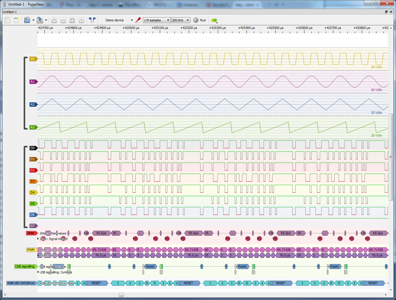
For initial testing I used first the Demo device, that generates semi-random signal you can look at without need for any hardware. I did the first tests with this Demo signal.
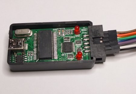
To be able to record real world signals, I need some supported hardware that can capture signals. Luckily I had several hardware that should be suitable. First I tried PulseView Windows to work with 8 logic channel Saelae clone device. It worked pretty much “plug and play” when I just plugged it in and selected to use FX2-based boards driver fx2lafw: Sigrok found the device with the drivers I had in my computer.
Next I tried to do the same with with USBee AX clone, that should be compatible (I think), but did not work “plug and play” as PulseView failed to find it. It seems that it would need some more work with the drivers. At the moment I did not want to mess up with the drivers as described at How to use it with PulseView (I think I would risk compatibility with some other software doing that). Maybe some later time.
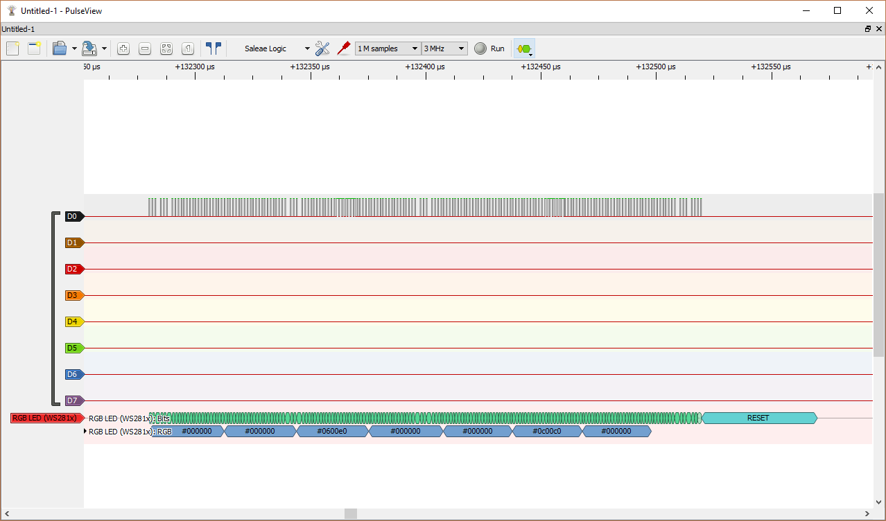
Next I tried RGB LED decoder with signal captured from my WS2812 addressable LEDs test circuit.
PulseView has a quite good list of supported protocol decoders (PDs) as the libsigrokdecode library ships with a collection of various protocol decoders out of the box. If that is not enough for your special needs, you can write your own too, of course; see Protocol decoder HOWTO and Protocol decoder API for details. Every protocol decoder is a Python module and has its own subdirectory in libsigrokdecode’s decoders directory. Protocol decoder HOWTO offers a minimalistic example of how a protocol decoder looks like.
Sigrok links:
https://sigrok.org/wiki/PulseView
https://sigrok.org/wiki/Supported_hardware
http://sigrok.org/wiki/Input_output_formats
https://en.wikipedia.org/wiki/Sigrok
https://www.sigrok.org/blog/blog
Related articles on signal analysis:
Signal analysis using Sigrok blog posting tells how to install Sigrok on Ubuntu and and capture signals with command-line utilities.
Rocking with sigrok article gives introduction to using sigrok commant line tools in Linux.
Logic analyzer: visualizing latency between two digital signals in real time with sigrok and matplotlib tells how to manipulate data extracted fromlogic analyzer with Python, to view the latency between two digital signals
High-Level Automated Hardware Debugging article shows how to use logic analyzers based on the FX2 chip with sigrok to debug hardware.
Collectd Wiki Plugin:sigrok page tells that sigrok plugin is a fully fledged libsigrok client, and can use any sigrok supported hardware to feed measurements to collectd and output data to RRDtool.
Sigrok: Using Logic to Debug Logic presentation slide set from Linux Foundation event gives introduction to usign sigrok
Information on logic analyzer hardware options:
fx2lafw is an open-source firmware for Cypress FX2 chips which makes them usable as simple logic analyzer hardware. The fx2lafw firmware is meant to work on any FX2-based hardware, including logic analyzers, FX2 eval boards, or other hardware which has this chip on-board.
How to use it with PulseView article tells how to use cheap “USBEE AX” logic analyzer with PulseView on Windows (tells the tricks how to configure Windows drivers).
Hobby Components low cost 8 channel logic analyser was first dedicated hardware for sigrok. Together with sigrok’s PulseView or sigrok-cli (command line version) software you can capture up to 8 digital logic channels at sample rates up to 24MHz.
Arduino logic analyser article tells how you can turn Arduino Uno R3 board to open logic sniffer compatible device (that should be supported with sigrok). You need code from .
USB-PD Sniffer article describes a USB-PD sniffing dongle with Type-C connectors.You can use the opensource Sigrok framework to acquire and decode USB Power Delivery traces with the USB-PD dongle.
Raspberry PI Logic Sniffer project turns the Raspberry PI into a logic sniffer that is compatible with sigrok. The logic sniffer runs on “bare metal”
A BeagleBone Logic Analyzer article tells that BeagleLogic realizes a logic analyzer on the BeagleBone Black using the Programmable Real-Time units and matching firmware and Linux kernel modules on the BeagleBone Black. BeagleLogic Turns your BeagleBoard into a 14-channel 100Msps Logic Analyzer page tells that with the sigrok project, BeagleLogic gets support for software triggering and decoding a large variety of digital communication protocols.
Related postings in this blog:
http://www.epanorama.net/newepa/2012/10/10/low-cost-logic-analyzers/
http://www.epanorama.net/newepa/2010/10/26/saelae-logic-analyzer/
http://www.epanorama.net/newepa/2013/01/28/debugging-rs-232-with-logic-analyzer/
http://www.epanorama.net/newepa/2013/02/11/open-logic-sniffer-software-and-hardware/
http://www.epanorama.net/newepa/2014/06/17/ht-usbee-axpro-review/
http://www.epanorama.net/newepa/2012/10/11/diy-logic-analyzers/
75 Comments
Tomi Engdahl says:
Everything You Need To Know About Logic Probes
http://hackaday.com/2017/07/29/everything-you-need-to-know-about-logic-probes/
comprehensive treasure trove of information regarding a subject that we should all know more about — sniffing logic signals. Sure, it’s a long video, but [Joel] of [OpenTechLab] leaves no stone unturned.
At the center of the video is the open-source sigrok logic capture and analyzer. It’s great because it supports a wide variety of dirt cheap hardware platforms, including the Salae logic and its clones. Logic is where it shines, but it’ll even log data from certain scopes, multimeters, power supplies, and more. Not only can sigrok decode raw voltages into bits, but it can interpret the bits as well using protocol decoder plugins written in Python. What this all means is that someday, it will decode everything. For free.
[Joel] knows a thing or two about sigrok because he started the incredibly slick PulseView GUI project for it, but that doesn’t stop him from walking you through the command-line interface, which is really useful for automated data capture and analysis, if that’s your sort of thing. Both are worth knowing.
In our opinion sigrok, and the el cheapo hardware logic probes that it supports deserve a place in every hacker’s toolbox. This video is the best introduction to the software, and the topic in general, that we’ve ever seen.
[001] Sigrok and Logic Analyzers
https://www.youtube.com/watch?v=dobU-b0_L1I
Tomi Engdahl says:
Cheap logic analyzer + Sigrok pulseview = timesaver (LHT00SU1)
https://www.youtube.com/watch?v=KiDDL5xtnG0
Cheap logic analyzer SPI i2c UART
https://www.youtube.com/watch?v=rR5cEFRO9_s
Tomi Engdahl says:
Getting Started with a $10 Logic Analyzer using Sigrok and PulseView
https://www.youtube.com/watch?v=z8Tdz7eQ8n4
Tomi Engdahl says:
Using a Logic Analyzer to Generate Screenshots from a Game Boy
http://hackaday.com/2017/08/01/using-a-logic-analyzer-to-generate-screenshots-from-a-game-boy/
Wouldn’t you like to go back to a dead handheld and extract the proof of your 90s-era high scores? Of course you would.
[svendahlstrand] bought his first logic analyzer, a Logic 8 from Saleae and decided to play around with an old Game Boy. He opened up the handheld with a tri-point screwdriver and hooked six wires up to the LCD data bus, generating screen shots from the logged data. He got screens from Solomon’s Club, Mole Mania, Kid Dracula, and more.
After figuring it out he posted his LCD sniffing tutorial to GitHub, where he also has a C program for manually piecing together the screen shots, pixel by pixel.
Sniff your Game Boy’s LCD using a logic analyzer
https://github.com/svendahlstrand/game-boy-lcd-sniffing
Tomi Engdahl says:
New protocol decoder: USB request
https://www.sigrok.org/blog/new-protocol-decoder-usb-request
libsigrokdecode has received support for another, quite interesting protocol decoder recently: usb_request.
It decodes USB transactions / requests from the packets received from the usb_packet decoder
In addition to emitting annotations (for displaying in GUIs), the PD also supports (currently) one SRD_OUTPUT_BINARY output type named “pcap”.
This will emit the decoded data in the widely-used PCAP format, which you can then further process in other tools such as Wireshark
Tomi Engdahl says:
USB-PD Sniffer
https://www.chromium.org/chromium-os/twinkie
This page describes a USB-PD sniffing dongle with Type-C connectors.
The dongle can be supported by Chrome devices as part of a USB-Type C implementation.
Capturing traces with the Sigrok tool
Tomi Engdahl says:
Hands-on review: Analyze signals with free, open-source sigrok PulseView
https://www.electronicproducts.com/Software/Development_Tools_and_Software/Hands_on_review_Analyze_signals_with_free_open_source_sigrok_PulseView.aspx
Sigrok is an awesome signal analysis software suite that works with a broad range of interfaces and instruments
The sigrok project is creating a portable, cross-platform, free and open-source signal analysis software suite that supports a wide variety of signal acquisition hardware, including logic analyzers, multimeters, oscilloscopes, and the like. While the suite contains several front-end subprojects, including sigrokcli (a command-line interface to manipulate sigrok), and sigrokqt (a Qt-based GUI to manipulate sigrok), in this article, I am concentrating on sigrok’s PulseView, an oscilloscope, logic analyzer, and mixed-signal (MSO) GUI front end.
The sigrock software consists of the following components:
Libsigrok: a shared library written in C, which contains the general infrastructure for handling logic analyzer data in a streaming fashion. It also contains the individual hardware drivers, which add support for various logic analyzers.
Libsigrokdecode: a shared library written in C, which contains the protocol decoder infrastructure and the protocol decoders themselves, which are written in Python.
Sigrokcli: a command-line front end, which uses both libsigrok and libsigrokdecode. It can acquire samples from logic analyzers and output them in various formats into files or to stdout and/or run protocol decoders on the acquired data.
Sigrokqt: a Qt-based GUI for sigrok, using both libsigrok and libsigrokdecode. This is intended to be a cross-platform GUI (it runs fine and looks native on Linux, Windows, and Mac OS X) supporting data acquisition and protocol decoding.
PulseView under Windows
One of the first things to notice is that the sigrok suite needs some kind of hardware to interface to the signals you want to examine. In order to use libsigrok (via a sigrok front end) on Windows, then, you need to install the proper driver for the desired device. If the device is connected through a (virtual) COM port, libsigrok doesn’t need a special driver; only the driver provided by the manufacturer is required.
USB is a different story, however. The device-specific USB driver shipped with vendor software is, in almost all cases, not going to work. Hence, you will need to install the WinUSB driver using the “Zadig” executable from the libwdi project. Fortunately, the PulseView installers ship with Zadig executable files for total convenience, and they’re accessible via the Windows “Start” menu.
Tomi Engdahl says:
[001] Sigrok and Logic Analyzers
https://www.youtube.com/watch?v=dobU-b0_L1I
Introduction and experiments with low-cost logic analysers and the sigrok software suite.
Tomi Engdahl says:
Cheap logic analyzer + Sigrok pulseview = timesaver (LHT00SU1)
https://www.youtube.com/watch?v=KiDDL5xtnG0
Tomi Engdahl says:
[011] USB Debugging with sigrok
https://www.youtube.com/watch?v=4FOkJLp_PUw
Advanced USB packet capture with logic analyzers and sigrok.
USB Debugging with sigrok
https://opentechlab.org.uk/videos:011:notes
Comments:
Excellent video buddy.
Very nice video. Shows the power of debugging software races through hardware techniques when you’re close to the hardware. On larger systems where I’ve worked you’re forced into debuggers or worse yet debugging through compilers (printf ugh!) . Heisenbugs become inevitable.
As usual ……informative, detailed ,well thought out video and debugging thought process. Thanks for the video.
Amazing video as always? Is it possible to capture the USB packets with 24MHz fx-2 Chinese clones? Or you chose DSLogic Plus Logic Analyzer since it support higher bandwidth?
Yeah 24MHz would be a cutting it a bit close on bandwidth. Also the FX2 logic analyzers are rather unreliable at max speed- they tend to halt if there’s even a tiny amount of congestion on the bus
If you stick to low speed (1.5MBps), it works. Full speed will likely not work, you need at least 2.5 oversampling (30 MS/s), better 4 (~50MS/s).
Tomi Engdahl says:
Sniffing the USB for answers
http://implementality.blogspot.com/2013/09/sniffing-usb-for-answers.html
The first bit was buying a logic analyser. I looked at getting a dedicated USB analyser but they tend to be a bit on the pricey side and, besides, they are very specialised – I don’t expect I will be doing too much USB sniffing so buying a special device just to sort out a particular bug was hard to justify. Since USB uses standard logic level signals I could get away with capturing the logic levels and using some software to decode what that translated to in terms of USB data. The added bonus is that I would have a tool for decoding other protocols such as SPI, one-wire, I2C, serial and so forth.
There are a lot of logic analysers based on the Cypress FX2 chips, these guys are just dumb samplers that feed the data back to a host PC over USB – all the triggering and data storage is done on the host.
The next step was the software. The salea came with software which is functional and has some decoding facilities but, unfortunately, those facilities don’t extend to decoding USB transactions. To decode the USB transactions I used the sigrok open source software to perform the decodes.
The spec says white is the D- signal, green is the D+ signal and black is ground. So I connected probe 0 (black) to the white wire and probe 1 (brown) to the green wire.
I configured a trigger to start sampling on the falling edge of D+ as this transition will happen when a device is plugged in and to sample at 24MHz. I then connected the arduino to the other end of the extension cable. The analyser triggered and started saving samples. I let the attach process for the arduino complete, then stopped the capture and exported the sample data as a VCD file.
Analysing the data was a challenge. The sigrok software is capable of doing it but, to be blunt, their documentation is rather poor.
The decoding was not always perfect, I think because the data rate of the USB was right at the limit of the sample rate for the logic analyser (remember Mr. Nyquist says you need a sample rate of at least twice your highest frequency to properly sample data) so sometimes I would see decode errors but, fortunately, the decode mostly worked right and provided us with valuable clues.
Tomi Engdahl says:
[001] Sigrok and Logic Analyzers
https://www.youtube.com/watch?v=dobU-b0_L1I
Introduction and experiments with low-cost logic analysers and the sigrok software suite.
Sigrok and Logic Analyzers
https://opentechlab.org.uk/videos:001:notes
Tomi Engdahl says:
Jason Gin Reverse Engineers a SanDisk High Endurance microSD, Just to Discover the Flash Type
https://www.hackster.io/news/jason-gin-reverse-engineers-a-sandisk-high-endurance-microsd-just-to-discover-the-flash-type-7f2f722e2cb2
After getting the runaround from SanDisk support, Gin turned to a carefully-soldered breakout and a logic analyzer for answers.
https://ripitapart.com/2020/07/16/reverse-engineering-and-analysis-of-sandisk-high-endurance-microsdxc-card/
I used my DSLogic Plus logic analyzer to analyze the signals on all of the pins. Since the data pinout was previously discovered, the hard part of figuring out what each line represented (data bus, control, address, command, write-protect, ready/busy status) was already done for me. However, not all of the lines were immediately evident as the pinouts I found online only included the bare minimum of lines to make the NAND Flash accessible, with one exception being a control line that places the controller into a reset state and releases its control of the data lines (this will be important later on).
By sniffing the data bus at the DSLogic’s maximum speed (and using its 32 MB onboard buffer RAM), I was able to get a clear snapshot of the commands being sent to the NAND Flash from the controller during initialization.
Tomi Engdahl says:
https://en.wikipedia.org/wiki/Sigrok
https://github.com/martinling/sigrok-cli-python
https://sigrok.org/wiki/Libsigrok
Tomi Engdahl says:
https://sigrok.org/wiki/Protocol_decoder_HOWTO
https://sigrok.org/wiki/Protocol_decoder_API
https://sigrok.org/wiki/Protocol_decoder_API/Queries
https://sigrok.org/wiki/Example_dumps
Tomi Engdahl says:
https://elinux.org/images/9/92/Sigrok_-_Using_Logic_to_Debug_Logic_-_ELCE_2013.pdf
Tomi Engdahl says:
Logic analyzer: visualizing latency between two digital signals in real time with sigrok and matplotlib
https://blog.savoirfairelinux.com/en-ca/2014/logic-analyzer-visualize-latency-with-sigrok-and-matplotlib/
Tomi Engdahl says:
https://sigrok.org/wiki/Protocol_decoder_output#SDR
https://sigrok.org/wiki/Protocol_decoder_API
http://www.polypux.org/projects/read-edid/
Tomi Engdahl says:
PulseView User Manual
https://sigrok.org/doc/pulseview/unstable/manual.html
Tomi Engdahl says:
https://github.com/droghio/sigrok
https://sigrok.org/wiki/Downloads
https://sigrok.org/wiki/Protocol_decoders
https://sigrok.org/wiki/Protocol_decoder_API#Required_functions
Tomi Engdahl says:
https://github.com/cranphin/sigrok-rc_switch
https://www.rudiswiki.de/wiki9/SigrokDecoder
https://research.kudelskisecurity.com/2020/01/08/decoding-lecroy-oscilloscope-traces-with-sigrok/
https://sigrok.org/wiki/Protocol_decoder_HOWTO
https://sigrok.org/wiki/Getting_started_with_a_logic_analyzer
.
Tomi Engdahl says:
libsigrok Toy Decoder
https://gist.github.com/geekman/c3a6d22741eb8cecd28e4191f67d39ad
This is a very minimal example for writing your own quick-and-dirty decoder that you can use in PulseView.
This decoder displays annotations for a signal that’s made up of 1 ms units. It annotates from one signal edge to another, without regard for time. If you want to handle the actual units of time, more logic is required and that’s left as an exercise for the reader
Tomi Engdahl says:
Recreating lab measurements as RTLstimulus
https://ntnuopen.ntnu.no/ntnu-xmlui/bitstream/handle/11250/2628808/no.ntnu:inspera:2544611.pdf?sequence=1
Most of modern IC design verification is conducted as RTL simulations. However, thefinal verification steps must be done on physical silicon.
This thesis investigates ways of assisting the designer in this process. By taking advantageof most stimulus applied to the DUT being part of a communication protocol, focus can bemoved from the signals them self, to the information transmitted by the signals. Decodingthe signals to a protocol level allows for reuse of existing testbenches. The informationbeing presented at a protocol level also makes analysis of the problem simpler for thedesigner.
Assuming a UVM testbench for the design already exist, the workflow proposed in thisthesis can be implemented with limited effort from the designer. Waveform files recordedwith a logic analyzer are decoded with easy to configure python scripts controlling protocoldecoders from the free/open source project Sigrok. Examples are presented on how toadapt an existing testbench to generate stimulus based on the decoded waveforms.
Tomi Engdahl says:
https://hackaday.com/tag/sigrok/
https://hackaday.com/2020/10/31/scratching-that-itch/
Tomi Engdahl says:
Need A Logic Analyzer? Use Your Pico!
https://hackaday.com/2022/03/02/need-a-logic-analyzer-use-your-pico/
There’s a slew of hardware hacker problems that a logic analyzer is in a perfect position to solve. Whether you’re trying to understand why an SPI LCD screen doesn’t initialize, what’s up with your I2C bus, or determine the speed of an UART connection, you’ll really want to have a logic analyzer on hand. People have been using a Pi Pico as a logic analyzer in a pinch, and now [pico-coder] has shared a sigrok driver that adds proper support for a Pico to beloved tools like Pulseview.
The specs offered are impressive. Compared to the $10 “Saleae” clone analyzers we are so used to, this thing boasts 21 digital channels with up to 120 MHz capture speed, 3 ADC channels at up to 500 KHz, and hardware-based triggers. The GitHub repository linked above stores the driver files out-of-tree, but provides build instructions together with an easily flash-able uf2 firmware.
https://github.com/pico-coder/sigrok-pico
Tomi Engdahl says:
Fix it Friday! (Logic Series 03) – Using a Logic Clip
https://www.youtube.com/watch?v=BNF1JfNes7U
In this Fix it Friday we demonstrate the extremely handy HP 548A Logic Clip.
Tomi Engdahl says:
Logic Analyzers: Tapping Into Raspberry Pi Secrets
https://hackaday.com/2023/08/31/logic-analyzers-tapping-into-raspberry-pi-secrets/
Today, I’d like to highlight a tool that brings your hacking skills to a whole new level, and does that without breaking the bank – in fact, given just how much debugging time you can save, how many fun pursuits you can unlock, and the numerous features you can add, this might be one of the cheapest tools you will get. Whether it’s debugging weird problems, optimizing your code, probing around a gadget you’re reverse-engineering, or maybe trying to understand someone’s open-source library, you are likely missing out a lot if you don’t have a logic analyzer on hand!
It’s heartbreaking to me that some hackers still don’t know the value that a logic analyzer brings. Over and over again, tactical application of a logic analyzer has helped me see an entirely different perspective on something I was hacking on, and that’s just the thing I’d like to demonstrate today.
Tomi Engdahl says:
TPM Bitlocker
Bypassing Bitlocker With A Logic Analzyer
https://hackaday.com/2023/08/25/bypassing-bitlocker-with-a-logic-analzyer/
Security Engineer [Guillaume Quéré] spends the day penetration testing systems for their employer and has pointed out and successfully exploited a rather obvious weakness in the BitLocker full volume encryption system, which as the linked article says, allows one to simply sniff the traffic between the discrete TPM chip and CPU via an SPI bus. The way Bitlocker works is to use a private key stored in the TPM chip to encrypt the full volume key that in turn was used to encrypt the volume data. This is all done by low-level device drivers in the Windows kernel and is transparent to the user.
TPM chip pins too small? Just find something else on the bus!
The whole point of BitLocker was to prevent access to data on the secured volume in the event of a physical device theft or loss.
Simply pulling the drive and dropping it into a non-secured machine or some other adaptor would not provide any data without the key stored by the TPM. However, since that key must pass as plaintext from the TPM to the CPU during the boot sequence, [Guillaume] shows that it is quite straightforward — with very low-cost tools and free software — to simply locate and sniff out this TPM-to-CPU transaction and decode the datastream and locate the key. Using little more than a cheapo logic analyser hooked up to some conveniently large pins on a nearby flash chip (because the SCK, MISO, and MOSI pins are shared with the TPM) the simple TIS was decoded enough to lock onto the bytes of the TPM frame.
Bypassing Bitlocker using a cheap logic analyzer on a Lenovo laptop
https://www.errno.fr/BypassingBitlocker.html
Have you ever been told that the company’s data on laptops is protected thanks to BitLocker? Well it turns out that this depends on BitLocker’s configuration…’
Capturing the TPM exchange
We’ll be using a dirt cheap logic analyzer, DSLogic Plus. I bought this for under $100 in 2021 (tax and shipping included).
A note on signal capture: to comfortably acquire a signal the sampling frequency should be 3 to 4 times the bus frequency. This means that for our SPI 33MHz bus we should sample at the very least at 100MHz. Notice that the specs of the analyzer state that it can do up to 400MHz on up to 16 channels. I’ll help you read between the lines here:
the more channels you capture at a time (by sets of 3), the lower the sampling frequency
you have to distinguish stream mode and buffer mode. The first one will send results directly to the host computer and permits capture of large sets, up to a minute but it’s limited to 100MHz on 3 channels. The buffer mode allows sampling at 400MHz but it will only work for a few milliseconds, so there’s no practical use for it here.
This means that this hardware can barely do the job we’re asking it to do. For a more professional option both hardware and software-wise (but also 10x pricier) have a look at Saleae. Otherwise there’s sigrok’s list of supported hardware.
As for plugging the analyzer to the board, remember that SPI is a shared bus. This means that there’s no need to capture the signal right at the tiny TPM pins if there is a larger SPI component on the board that the hooks can be latched on to. From experience I identified a neighbouring SPI flash, but fortunately all components are marked so it’s rather easy to identify their use by looking up their datasheet.
SPI has several lines but only 3 can be captured using the DSLogic because otherwise the sampling frequency drops. The 3 most important ones are the clock CLK and the two data lines MOSI and MISO.
The threshold voltage (level at which the analyzer decides that the line has changed states) should be around half of the signal’s voltage, here the latter was measured at 3.3V so an appropriate threshold is around 1.6V.
Decoding the captured signal
There are 3 layers to decode:
SPI, which is the physical layer
TIS
TPM2.0, which contains the VMK
SPI
As far as SPI is concerned any logic analyzer should do this properly
TIS
TIS, which stands for TPM Interface Specification, is another beast entirely and that’s where I had most of my troubles. I couldn’t find a decoder that worked for my capture and decided to do it “manually”. Short of correctly decoding the data, the libsigrock decoders did at least indicate a rough window for the TPM exchanges which was a welcome tip since each capture has several million bytes of data. Maybe the decoders fail be because the capture is missing Chip Select (CS#) which is required in the TPM specification, maybe because the clock is incorrect, maybe because some bytes are occasionally missing, maybe for some other reason, who knows.
TPM 2.0
The TPM command that requests the key be sent back is the TPM2_Unseal command. It is described in part 3 of the TPM 2.0 specification.
You might ask how I isolated the frames below since no decoder would work. We don’t actually care about the requests happening on MOSI, we’re mostly interested in the responses on the MISO line. As we’ve seen previously the TIS encoding around TPM bytes is rather simple, so the simplest way to isolate all TPM transactions is to filter the raw SPI data using the mask “80 00 00 00 01 ..” and only keep this wildcard last byte.
In the buffer lies our key, it starts with 5761 and is 32 bytes long.
Mounting and backdooring the disk
Mounting the disk live in read/write mode (if you’d rather work offline do a disk copy with dd and then mount this copy using a loop device):
echo 5761A391DF1F00E1B3852828C6DDA6F9A5FEACE971A4AAAE442518F74AA7FED6E0FC | xxd -r -p > key
dislocker-fuse -K key /dev/sdd3 ./mnt/
mount ./mnt/dislocker-file ./mnt2/
Then the simplest backdoor is to just overwrite the sticky keys program with cmd
Limitations
I cannot recommend using the DSLogic for this task:
a lot of captures were duds and had to be thrown away
sampling at 3 times the bus speed was barely enough to have a coherent clock and some bytes were missing
This forced me to spend way too much time to understand the protocols in order to decode the capture. In the end time is money, if you’re an employer reading this just buy a professional logic analyzer for your employees.
Takeaways
The use of a discrete (physical) TPM does not increase the security of the system as one would expect and creates the illusion of security.
To protect against this attack you could either use a fTPM or if the discrete TPM has to be used, then it is necessary to set a PIN or passphrase on BitLocker (as recommmended by Microsoft).
Tomi Engdahl says:
Logic Analyzers: Tapping Into Raspberry Pi Secrets
https://hackaday.com/2023/08/31/logic-analyzers-tapping-into-raspberry-pi-secrets/
I’m using a $10 logic analyzer you can get off Aliexpress or Amazon, a laptop, and a Raspberry Pi with an SD card and a power supply.
Tomi Engdahl says:
USB logic analyzer microcontroller is suitable for ARM FPGA debugging tool 24M sampling 8 channels
https://www.aliexpress.com/item/1005005817667297.html?spm=a2g0o.detail.0.0.5408tGjGtGjGBp&gps-id=pcDetailTopMoreOtherSeller&scm=1007.40000.327270.0&scm_id=1007.40000.327270.0&scm-url=1007.40000.327270.0&pvid=2069ebe6-b5c3-47bc-87eb-f901213749db&_t=gps-id:pcDetailTopMoreOtherSeller,scm-url:1007.40000.327270.0,pvid:2069ebe6-b5c3-47bc-87eb-f901213749db,tpp_buckets:668%232846%238116%232002&pdp_npi=4%40dis%21EUR%216.95%215.7%21%21%2153.33%21%21%402103246c16940729750195889e112d%2112000034456281459%21rec%21FI%212528467667%21S&search_p4p_id=202309070049350518943776579770657375_11
EZ-USB FX2LP CY7C68013A USB logic analyzer core board+Source Code
https://www.aliexpress.com/item/1005004997973484.html?spm=a2g0o.detail.0.0.de653dpR3dpRLe&gps-id=pcDetailTopMoreOtherSeller&scm=1007.40000.327270.0&scm_id=1007.40000.327270.0&scm-url=1007.40000.327270.0&pvid=425cb746-3d5a-453b-bb4a-4214ee232554&_t=gps-id:pcDetailTopMoreOtherSeller,scm-url:1007.40000.327270.0,pvid:425cb746-3d5a-453b-bb4a-4214ee232554,tpp_buckets:668%232846%238116%232002&pdp_npi=4%40dis%21EUR%216.52%215.02%21%21%216.83%21%21%402103246c16940728059123835e112d%2112000031294125966%21rec%21FI%212528467667%21S&search_p4p_id=202309070046459422000890369144589743_5
Tomi Engdahl says:
USB Logic Analyzer 24MHz 8 Channel 24M/seconds Logic Analyzer Debugger For ARM FPGA Logic Analyzer Logic 24M 8CH
https://www.aliexpress.com/item/1005005389032154.html?spm=a2g0o.detail.0.0.cc08VsURVsURiN&gps-id=pcDetailTopMoreOtherSeller&scm=1007.40000.327270.0&scm_id=1007.40000.327270.0&scm-url=1007.40000.327270.0&pvid=73fe3399-c52c-4318-b9f1-370fe7d0d917&_t=gps-id:pcDetailTopMoreOtherSeller,scm-url:1007.40000.327270.0,pvid:73fe3399-c52c-4318-b9f1-370fe7d0d917,tpp_buckets:668%232846%238111%231996&pdp_npi=4%40dis%21EUR%215.33%214.8%21%21%215.59%21%21%402103146c16940784407076232e1268%2112000032852336326%21rec%21FI%212528467667%21S&search_p4p_id=202309070220407431270967067542068073_0
NanoDLA Logic Analyzer TYPE-C SCM ARM FPGA Debugging Protocol Analysis 24MHz SampleRate 8 Channels Open Source Sigrok PulseView
https://www.aliexpress.com/item/1005005680498612.html?spm=a2g0o.detail.0.0.cc08VsURVsURiN&gps-id=pcDetailTopMoreOtherSeller&scm=1007.40000.327270.0&scm_id=1007.40000.327270.0&scm-url=1007.40000.327270.0&pvid=73fe3399-c52c-4318-b9f1-370fe7d0d917&_t=gps-id:pcDetailTopMoreOtherSeller,scm-url:1007.40000.327270.0,pvid:73fe3399-c52c-4318-b9f1-370fe7d0d917,tpp_buckets:668%232846%238111%231996&pdp_npi=4%40dis%21EUR%216.32%214.55%21%21%216.62%21%21%402103146c16940784407076232e1268%2112000033991699774%21rec%21FI%212528467667%21S&search_p4p_id=202309070220407431270967067542068073_3
Tomi Engdahl says:
DLA Logic Analyzer ARM FPGA Debugging Tool Protocol Analysis 24MHz Sampling Rate 8 Channels Open Source Sigrok PulseView
https://www.aliexpress.com/item/1005005554828963.html?src=criteo&albch=criteo_New&acnt=criteo-LF&albcp=157651&device=pc&clickid=64f9de9b2d794274a82ca4a4c2ea7fa8_1694097051_1005005554828963&aff_fcid=06de10a918b640acb68d0c50542feb53-1694097080889-08329-UneMJZVf&aff_fsk=UneMJZVf&aff_platform=aaf&sk=UneMJZVf&aff_trace_key=06de10a918b640acb68d0c50542feb53-1694097080889-08329-UneMJZVf&terminal_id=a84dd682a66047c694dfe5628f2eb974&afSmartRedirect=y
Tomi Engdahl says:
Agreeing By Disagreeing
https://hackaday.com/2023/09/09/agreeing-by-disagreeing/
And in the end, we both absolutely agreed on the fact that great open-source software has made the modern logic analyzers as useful as they are, and the lack thereof is also partially responsible for the demise of the old beasts. Well, that and he needs a lab cart then to carry around what I can slip in my pocket today. Take that!
https://sigrok.org/wiki/PulseView
Tomi Engdahl says:
8 Channels Mini Logic Analyzer Microcontroller ARM FPGA Debugging Tool 24MHZ Sampling Type-C USB Interface
https://www.aliexpress.com/item/1005005734480096.html?src=criteo&albch=criteo_New&acnt=criteo-LF&albcp=157651&device=pc&clickid=64fec2937e1e6e50dbe7ea9c790025cb_1694417555_1005005734480096&aff_fcid=e0245520b9d94247a3659a79ac646037-1694417574469-06640-UneMJZVf&aff_fsk=UneMJZVf&aff_platform=aaf&sk=UneMJZVf&aff_trace_key=e0245520b9d94247a3659a79ac646037-1694417574469-06640-UneMJZVf&terminal_id=a84dd682a66047c694dfe5628f2eb974&afSmartRedirect=y
DLA Logic Analyzer ARM FPGA Debugging Tool Protocol Analysis 24MHz Sampling Rate 8 Channels Open Source Sigrok PulseView
https://www.aliexpress.com/item/1005005554828963.html?spm=a2g0o.detail.0.0.2a55UwQLUwQLtZ&gps-id=pcDetailTopMoreOtherSeller&scm=1007.40000.327270.0&scm_id=1007.40000.327270.0&scm-url=1007.40000.327270.0&pvid=b8ad9a69-e120-4411-ac7f-5f9aa99fe612&_t=gps-id:pcDetailTopMoreOtherSeller,scm-url:1007.40000.327270.0,pvid:b8ad9a69-e120-4411-ac7f-5f9aa99fe612,tpp_buckets:668%232846%238111%231996&pdp_npi=4%40dis%21EUR%211.64%211.56%21%21%211.72%21%21%402101c5b116944175767391011e1ffd%2112000033523872509%21rec%21FI%212528467667%21S&search_p4p_id=202309110032567737090786108880837830_1
Tomi Engdahl says:
USB Logic Analyzer 24MHz 8 Channel 24M/seconds Logic Analyzer Debugger For ARM FPGA Logic Analyzer Logic 24M 8CH
https://www.aliexpress.com/item/1005005639218752.html?spm=a2g0o.detail.0.0.652f1f34FmRjfc&gps-id=pcDetailTopMoreOtherSeller&scm=1007.40000.327270.0&scm_id=1007.40000.327270.0&scm-url=1007.40000.327270.0&pvid=dff0e5bf-8d0c-4aa4-9abf-07961dbb42f5&_t=gps-id:pcDetailTopMoreOtherSeller,scm-url:1007.40000.327270.0,pvid:dff0e5bf-8d0c-4aa4-9abf-07961dbb42f5,tpp_buckets:668%232846%238111%231996&pdp_npi=4%40dis%21EUR%218.89%216.22%21%21%2168.30%21%21%402103249616944441299968516ef278%2112000033845434177%21rec%21FI%212528467667%21S&search_p4p_id=202309110755300261523868422064556804_2
Tomi Engdahl says:
USB Logic Analyzer 24MHz 8 Channel 24M/seconds Logic Analyzer Debugger For ARM FPGA Logic Analyzer Logic 24M 8CH
https://www.aliexpress.com/item/1005004866074298.html?spm=a2g0o.detail.0.0.1a21WKiyWKiyGn&gps-id=pcDetailTopMoreOtherSeller&scm=1007.40000.327270.0&scm_id=1007.40000.327270.0&scm-url=1007.40000.327270.0&pvid=6944c85e-41e4-4399-ae22-22dfac758e3e&_t=gps-id:pcDetailTopMoreOtherSeller,scm-url:1007.40000.327270.0,pvid:6944c85e-41e4-4399-ae22-22dfac758e3e,tpp_buckets:668%232846%238111%231996&pdp_npi=4%40dis%21EUR%215.72%215.72%21%21%215.99%21%21%402103249616944442896753791ef278%2112000030805575007%21rec%21FI%212528467667%21S&search_p4p_id=202309110758097072240987312777446114_6
Tomi Engdahl says:
USB Logic Analyzer 24MHz 8 Channel 24M/seconds Logic Analyzer Debugger For ARM FPGA Logic Analyzer Logic 24M 8CH
https://www.aliexpress.com/item/1005005388926667.html?spm=a2g0o.detail.0.0.2249pVvkpVvk2P&gps-id=pcDetailTopMoreOtherSeller&scm=1007.40000.327270.0&scm_id=1007.40000.327270.0&scm-url=1007.40000.327270.0&pvid=ed9c0273-abca-488e-9a81-41c6864cfd05&_t=gps-id:pcDetailTopMoreOtherSeller,scm-url:1007.40000.327270.0,pvid:ed9c0273-abca-488e-9a81-41c6864cfd05,tpp_buckets:668%232846%238111%231996&pdp_npi=4%40dis%21EUR%215.34%214.8%21%21%215.59%21%21%402103249616944443201964498ef278%2112000032852332807%21rec%21FI%212528467667%21S&search_p4p_id=202309110758402283340685317750003948_7
Tomi Engdahl says:
10Pcs Test Hook Clip Logic Analyzer Cable Jumper Wire Yellow/Red/Black/Green/White/Blue Test Clamp Kit 20/30CM
https://www.aliexpress.com/item/1005004938665294.html?spm=a2g0o.detail.0.0.5ca5luBcluBcV4&gps-id=pcDetailTopMoreOtherSeller&scm=1007.40000.327270.0&scm_id=1007.40000.327270.0&scm-url=1007.40000.327270.0&pvid=e2da07fb-d2b5-44ed-8edd-43d0b8ad9f5d&_t=gps-id:pcDetailTopMoreOtherSeller,scm-url:1007.40000.327270.0,pvid:e2da07fb-d2b5-44ed-8edd-43d0b8ad9f5d,tpp_buckets:668%232846%238111%231996&pdp_npi=4%40dis%21EUR%213.96%213.01%21%21%214.15%21%21%402103249616944443606205328ef278%2112000031092094510%21rec%21FI%212528467667%21S&search_p4p_id=202309110759206506079859959598551526_11
Tomi Engdahl says:
USB Logic Analyzer 24MHz 8 Channel 24M/seconds Logic Analyzer Debugger For ARM FPGA Logic Analyzer Logic 24M 8CH
https://www.aliexpress.com/item/1005004866074298.html?src=criteo&albch=criteo_New&acnt=criteo-LF&albcp=157651&device=pc&clickid=65002806061513728a2629d38a285172_1694509062_1005004866074298&aff_fcid=49347fb563224bd297d057a6359474e2-1694509125225-04089-UneMJZVf&aff_fsk=UneMJZVf&aff_platform=aaf&sk=UneMJZVf&aff_trace_key=49347fb563224bd297d057a6359474e2-1694509125225-04089-UneMJZVf&terminal_id=a84dd682a66047c694dfe5628f2eb974&afSmartRedirect=y
Tomi Engdahl says:
Data Repair Tool SD Card Repair Memory Card Repair Test Flying Cable Tool PC3000 FE Tool
https://www.aliexpress.com/item/1005004738971704.html?spm=a2g0o.detail.1000014.28.6e85KqJsKqJs4I&gps-id=pcDetailBottomMoreOtherSeller&scm=1007.40000.326746.0&scm_id=1007.40000.326746.0&scm-url=1007.40000.326746.0&pvid=dc832572-f960-44c7-9cdc-23283516e37a&_t=gps-id:pcDetailBottomMoreOtherSeller,scm-url:1007.40000.326746.0,pvid:dc832572-f960-44c7-9cdc-23283516e37a,tpp_buckets:668%232846%238111%23456&pdp_npi=4%40dis%21EUR%2177.30%2176.52%21%21%2181.10%21%21%402101c5b116945234945341337e56be%2112000030297109130%21rec%21FI%212528467667%21S
When repairing data, you may need to solder the flying leads, which may damage your data card and cause great inconvenience to the operation. In order to create a good tool for the majority of electronic engineers, we have developed this for you. Data repair shop tool, the needle can move up and down, up and down, you can also adjust the position. There are 10 sets of needles on our kits. If you need more needles, you can buy them separately. I hope this tool can help you.
Tomi Engdahl says:
How does a USB keyboard work?
https://www.youtube.com/watch?v=wdgULBpRoXk
The USB 2.0 spec: https://eater.net/downloads/usb_20.pdf
Tomi Engdahl says:
https://hackaday.com/2023/09/12/logic-analyzers-capabilities-and-limitations/
Tomi Engdahl says:
1 set of USB Logic analyzer 24MHz 8-channel 24M/s ARM FPGA Logic analyzer debugger Logic analyzer logic 24M 8CH
https://www.aliexpress.com/item/1005005866283269.html?spm=a2g0o.detail.0.0.3bbc5DIZ5DIZVv&gps-id=pcDetailTopMoreOtherSeller&scm=1007.40000.327270.0&scm_id=1007.40000.327270.0&scm-url=1007.40000.327270.0&pvid=b9b42d44-4942-444b-9821-da71a4a1b19d&_t=gps-id:pcDetailTopMoreOtherSeller,scm-url:1007.40000.327270.0,pvid:b9b42d44-4942-444b-9821-da71a4a1b19d,tpp_buckets:668%232846%238111%231996&pdp_npi=4%40dis%21EUR%215.58%215.58%21%21%215.85%21%21%40210313e916946725192395804ea0fb%2112000034628875760%21rec%21FI%212528467667%21S&search_p4p_id=202309132321592725061557845494742238_2
Tomi Engdahl says:
How does USB device discovery work?
https://www.youtube.com/watch?v=N0O5Uwc3C0o
What happens when you first plug a USB device in? There’s a whole bunch of negotiation where the computer discovers what a USB device is capable of. In this video I capture the conversation and walk through what’s going on
Tomi Engdahl says:
https://hackaday.com/2023/10/09/decoding-the-8088/
Tomi Engdahl says:
https://sigrok.org/wiki/Protocol_decoder_HOWTO
Tomi Engdahl says:
https://github.com/pysigrok/pysigrok
Tomi Engdahl says:
Managing sigrok-cli data with Python
https://sigrok.org/wiki/Managing_sigrok-cli_data_with_Python
This page provides an example of how to incorporate sigrok-cli input commands and output data into a Python script. This allows for the easy setup of automated testing, data plotting and analysis. Note that sigrok-meter already serves this function for some devices, but does not currently support oscilloscopes.
http://sigrok.org/wiki/Protocol_decoder_HOWTO
Tomi Engdahl says:
pysigrok
This re-implements the sigrok core and utilizes Python’s entry points for plugins. This alleviates the need for a central repo of decoders, hardware and file format implementations.
https://github.com/pysigrok/pysigrok
Tomi Engdahl says:
https://github.com/ultraembedded/openlogicbit?tab=readme-ov-file