A grid-tie inverter converts direct current (DC) into an alternating current (AC) suitable for injecting into an electrical power grid, normally 120 V RMS at 60 Hz or 240 V RMS at 50 Hz. Grid-tie inverters are used between local electrical power generators: solar panel, wind turbine, hydro-electric, and the grid. They range from small 250 watt micro inverters that sit under each individual solar panel, up to single units of many kWs to allow larger 10 kW wind generators and solar arrays to be grid-connected.
An Engineer’s Guide to Power Inverters for Solar Energy Harvesting article gives a good introduction on the circuit techniques used on solar inverters including grid tie inverters.

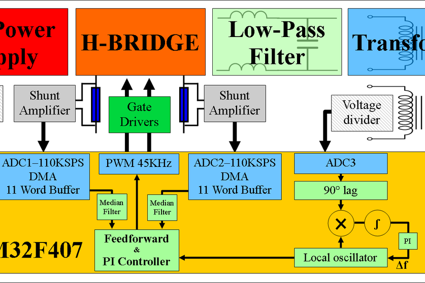
To inject electrical power efficiently and safely into the grid, grid-tie inverters must accurately match the voltage and phase of the grid sine wave AC waveform. It must be also designed for electrical safety in mind. Inverters now include all the necessary protective functions needed to synchronize safely and reliably with the utility grid, to protect utility power quality, and to prevent “islanding” by preventing backfeeding during a utility power outage.
Grid-tie inverters are also designed to quickly disconnect from the grid if the utility grid goes down. This is an electrical code requirement in many counties. It that ensures that in the event of a blackout, the grid tie inverter shuts down to prevent the energy it transfers from harming any line workers who are sent to fix the power grid.
One of the most important aspects of the inverter is the anti-islanding circuit that prevents the inverter from energizing the “dead” power system. The anti-islanding circuit is designed to keep the utility electrical system (both premises wiring and utility feeder) safe in the event that the utility is being serviced or is disconnected at some point in the transmission system, distribution system or premises wiring system. If the utility power is suddenly not present at the output terminals for any reason (inverter ac output disconnect opened, service disconnect opened, meter removed from the socket, utility maintenance, or utility blackout), the inverter senses this and immediately ceases to send power to the output terminals
Anti-inlanding circuit prevents the inverter from delivering ac power if the utility voltage and frequency are not present, or if they are not within narrowly defined limits. This circuit monitors the voltage and frequency at the output terminals of the inverter. If the voltage varies more than plus ten percent or minus twelve percent from the nominal output voltage the inverter is designed for (120, 230, 208, 240 277, 400 or 480 volts), the inverter cannot send power to the output terminals. Nor, is there any voltage on these terminals when the inverter shuts down. In a similar manner, if the frequency is not right it shuts down.
Grid tie inverters are complicated devices covered by many regulations, so not idea for DIY. But it has not stopped for some people to try.
BUILD YOUR OWN GRID TIE INVERTER article and Grid Tie Inverter Walkthrough video describe a 40-60w transformer based grid tie inverter project. It does all the functions you need: DC to AC conversion as well as phase and voltage matching. Instructables project Grid Tie Inverter gives more details. Remember safety guidelines.
2 Comments
Tomi Engdahl says:
EEVblog 1518 – Hoymiles Solar Microinverter TEARDOWN
https://www.youtube.com/watch?v=_H4IP_iEzWw
Depotting, teardown, and some reverse engineering schematic analysis of the 400W Hoymiles solar microinverter.
00:00 – Hoymiles 400W Micro Inverter
01:05 – Removing the silicone thermal potting compound
04:20 – Mains wiring and dangers of high voltage DC string inverters
05:43 – Installation requirements. Electrican vs solar installer
06:40 – PCB top side
07:54 – Anti-islanding safety feature
09:56 – What’s a bit of flex…
10:48 – Bottom the PCB
11:41 – Reverse engineering time
15:57 – Mains voltage and frequency detection
17:03 – Schematic
https://www.eevblog.com/forum/blog/eevblog-1518-hoymiles-solar-microinverter-teardown/
CORRECTIONS: https://www.youtube.com/watch?v=yOJ7xPugsdc
Tomi Engdahl says:
#mdpienergies #highlycitedpaper
State-of-the-Art of Mini Grids for Rural Electrification in West Africa
https://t.ly/dwCDD
University of La Rioja
Colorado State University
Authors: Fernando A. et. al
#minigrid #ruralelectrification #offgridenergy