This article is about measuring resistance, capacitance and inductance. The measurements described here talks about measuring components that not wired into any circuit.
Resistors, Inductors and Capacitors are the most commonly used passive components in almost every electronics circuit. Out of these three the value of resistors and capacitors are commonly marked on top of it either as resistor colour code or as numeric marking. Also the resistance and capacitance can also be measured using normal Multimeter. But most of the inductors, especially the ferrite cored and air cored ones for some reason does not seem to have any sort of marking on them. This becomes quite annoying when you have to select the right value of inductor for your circuit design or have salvaged one from an old electronic PCB and wanted to know the value of it.
Resistance with a multimeter
Resistance is the measure of difficulty electrons have in flowing through a particular object. Resistance can be measured with an analog or digital multimeter or ohmmeter. Resistance is can be usually usually most easily measured using an instrument such as digital multimeter.
Resistance measurement does not involve measuring the circuit’s resistance value itself. Instead, resistance is calculated by measuring the current and voltage applied to the circuit. Resistance can be calculated by measuring the current and voltage using Ohm’s Law.
Many multimeters typically apply a low current to the circuit under measurement, the circuit (resistance) exhibits a voltage a voltage drop related to resistance value. In most cases, when measuring resistance with a digital multimeter, you’ll use the two-terminal measurement method. This method applies a constant current and measures the resistance value using the instrument’s voltmeter. There are advanced meters that use a four-terminal resistance measurement for more accurate low-resistance measurement.
Capacitance measurements
Many modern “better” multimeters have a measurement range to measure capacitance. Simple DMMs can measure capacitance by just charging the capacitor with a constant current and measuring the rate of voltage build-up. This simple technique provides surprisingly good accuracy and wide dynamic range, therefore it can be implemented in almost any DMM, without significant cost penalties. There are other techniques as well: A multimeter determines capacitance by charging a capacitor with a known current, measuring the resulting voltage, then calculating the capacitance. Those multimeter capacitor measurements are simple to use, but can have limited accuracy. Capacitors measured by means of a multimeter in capacitance mode may be expected to read low by as much as 10%. This accuracy is sufficient for many applications such as the starting circuit for an electric motor or for power supply filtration. Greater accuracy is available by performing a dynamic test.
A capacitance meter is a piece of electronic test equipment used to measure capacitance, mainly of discrete capacitors. Depending on the sophistication of the meter, it may display the capacitance only, or it may also measure a number of other parameters such as leakage, equivalent series resistance (ESR), and inductance. For more details on capacitor measurements check out IFIXIT Introduction to Capacitors.
You can to check bad Capacitors in circuit boards with ESR meter and multimeter that can measure capacitance. For more details on this check out 3 Ways to Check Capacitors in Circuit with Meters & Testers video. If you are interested in capacitor ESR measurements, check my posts on ESR meters and DIY ESR meter.
Inductance measurements
Inductance is usually measured in units called millihenrys or microhenrys. It is commonly measured by using a frequency generator and an oscilloscope or an LCR multimeter. The only reason DMMs can’t measure inductances is that it is more difficult to measure inductance than resistance or capacitance: this task requires special circuitry, which is not cheap. Since there are relatively few occasions when inductance measurements are required, standard DMMs do not have this functionality, which allows for lower cost.
Theoretically, one could measure inductance by applying a constant voltage across an inductor and measuring the current build-up; however, in practice this technique is much more complicated to implement, and the accuracy is not that good. It can be also hard to separate ESR from reactive value at low frequencies unless a dc resistance measurement is also taken. The DC resistance itself is easy to measure separately with a multimeter resistance measurement range.
RLC meter instruments
LCRs are special meters designed for inductance measurements and containing the required circuitry. These are costly tools.
A basic LCR meter is very similar to a multimeter. With the RLC measurement electrical components can be measured in detail.
determine resistance (R), inductance (L) and capacitance (C).
The simplest method to measure L or C is with a series resistor and a low frequency oscillator. A cheap DMM and a cheap LCR will both use this method. The accuracy with DMM or LCR will therefore be similar. However, because inductors have more parasitic effects than capacitors, like resistance, leakage flux, saturation, non-linearity, hysteresis, eddy currents, frequency depending mu, the simple measurement of the inductivity may not be sufficient for you. The cheaper ones are accurate enough, but don’t distinguish resistance from inductance when measuring coils, so you need to know both to get an accurate reading. Like all things, you get what you pay for.
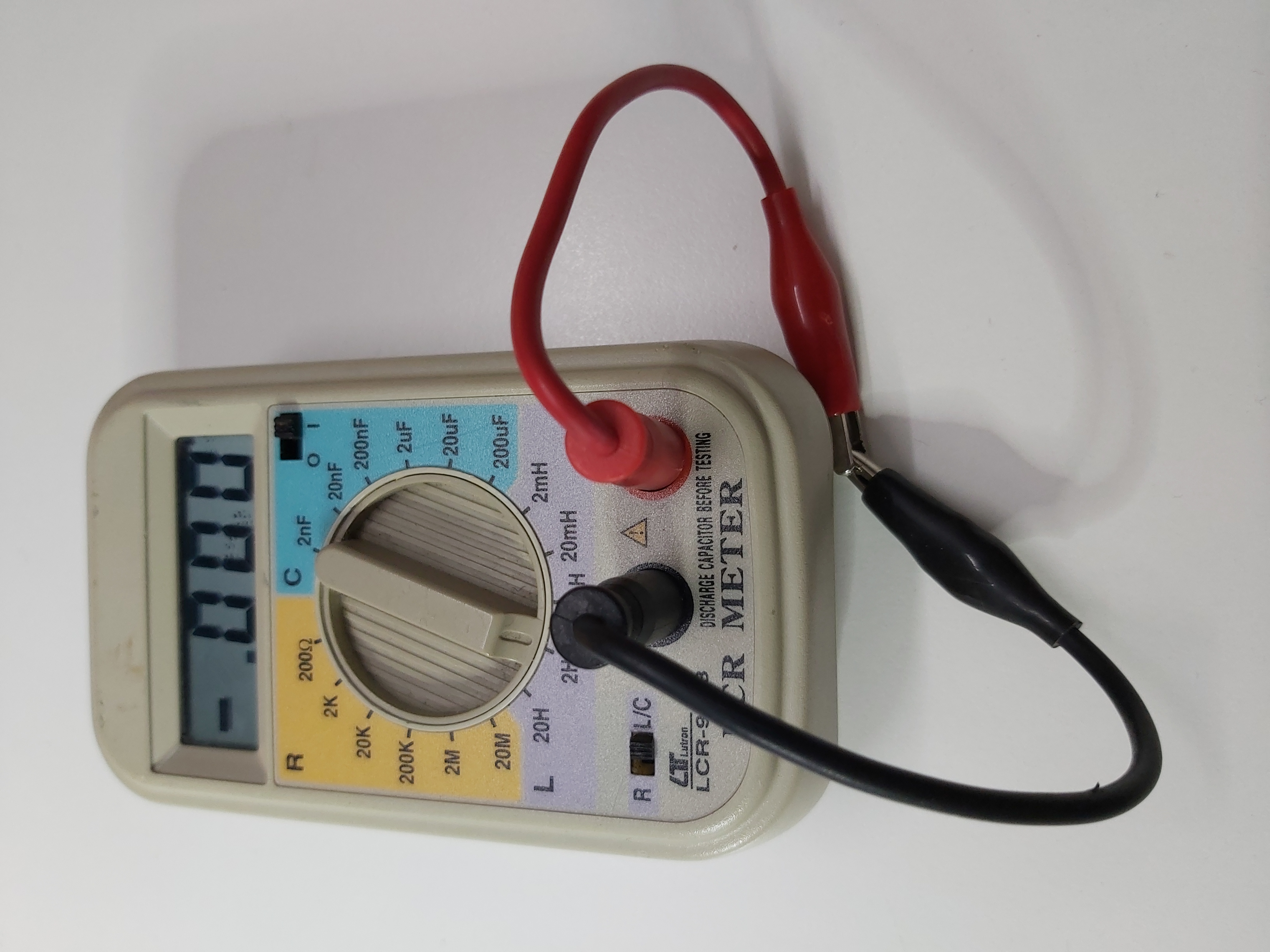
I own Lutron LCR-9063 that I use to make RLC measurements (it is similar to VOLTCRAFT LCR-9063 LCR-meter):
There are also more advanced meters that simultaneously measures the voltage across and current through the device. From the ratio of these amounts it algebraically calculates the impedance. The measurement results from programming (stimulus) an AC voltage/current with a given frequency and the measurement of the voltage curve and the current profile.
Subsequently, advanced meters measure the phase angle between the applied voltage and resulting current. The simultaneous determination of current (I) and voltage (U) in short intervals over a period of several intervals allows for the determination of the phase angle between U and I.
They use this information to display the equivalent capacitance, inductance, and resistance of the device in question. The meter operates under the assumption that the capacitance and inductance it detects exist in either a parallel or series configuration.
Der EE DE-5000 Handheld LCR Meter is one more advanced meter I seen. It can do measurement at many frequencies. For more details on it check out Der EE DE-5000 Unboxing and Teardown.
Multi component testers
There are many cheap tester circuit boards, DIY kits and ready made instruments marketed like $20 LCR ESR Transistor checker. Those instruments can measure transistors, resistors, capacitors and inductors. You can but those from online market, and their capacitance meter usually also ESR meter built in.
For capacitance, inductance and resistance measurements I have successfully used component testers like this:
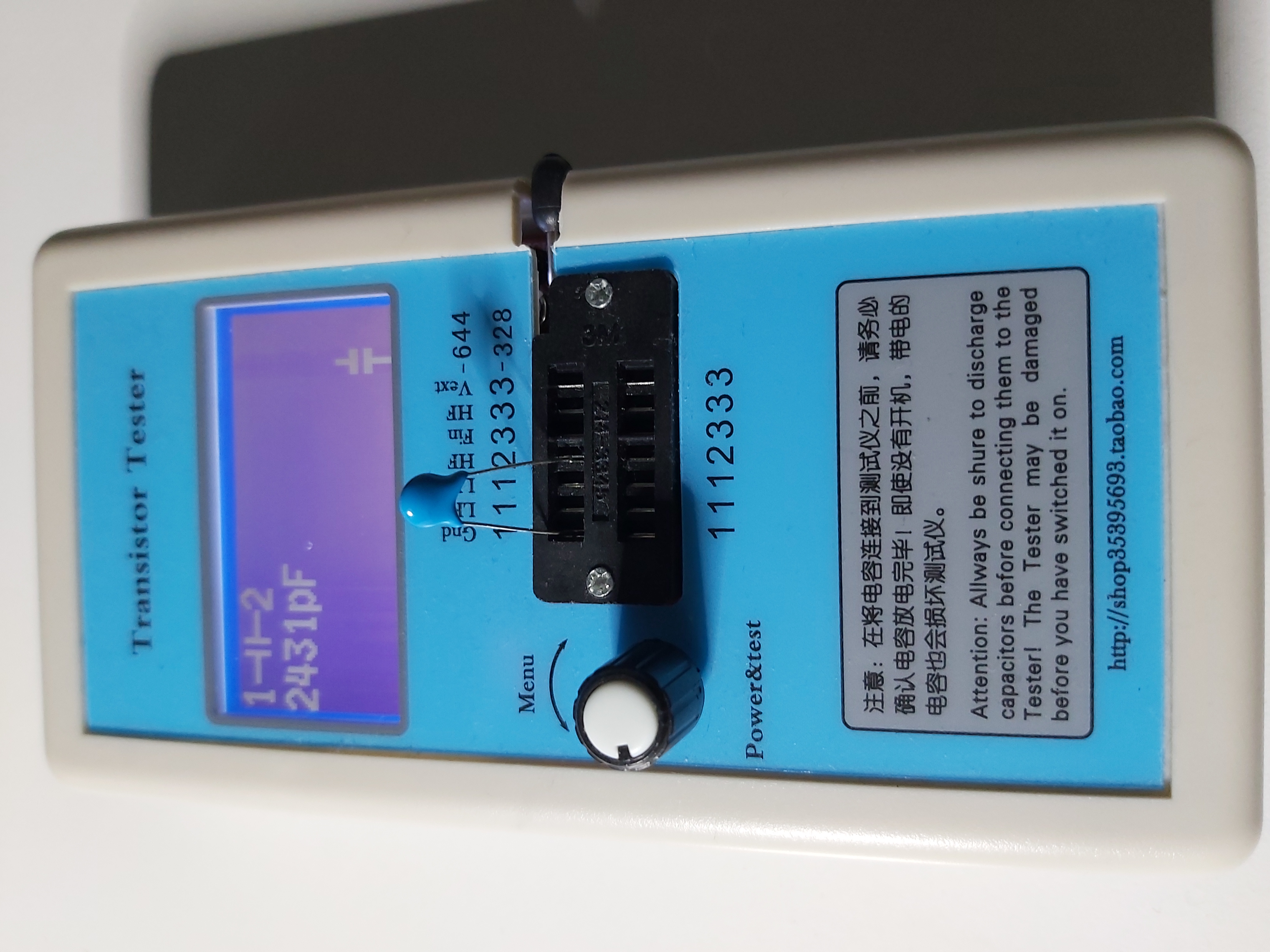
I have tested several different component tester DIY kits and boards:
DIY Electronics Tester Kit M168
Component tester M12864
Transistor tester M12864 advanced version
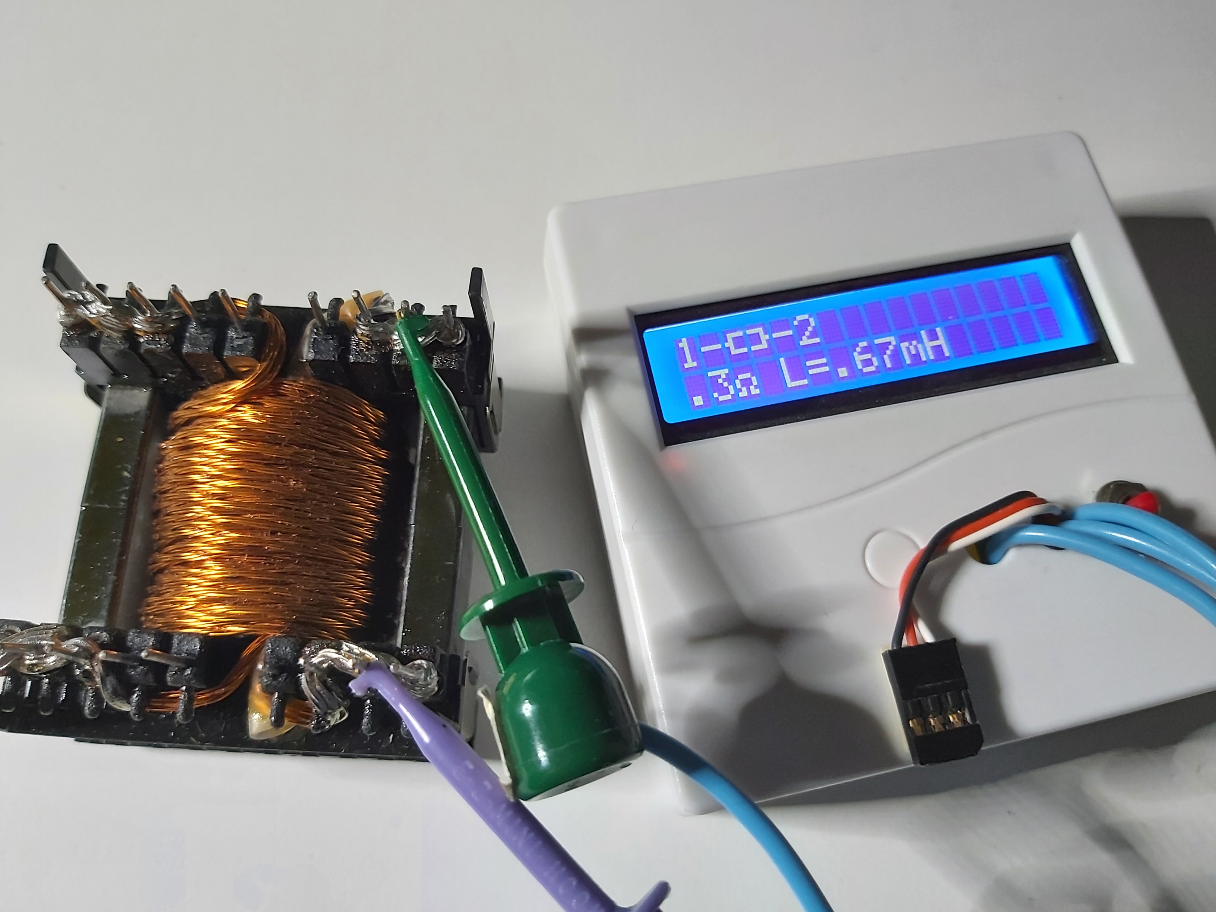
They are good for many things, but have limitations also – do not always give accurate inductance reading with some coils that use large iron or ferrite core. The reason is that those testers typically measure the inductance with a short measurement pulse that can behave somewhat differently with magnetic core than continuous waveform sent by specific RLC meters.
Audio measurement instruments
There are audio measurement tools that are designed to measure different audio system components like speaker elements and passive components. For example DATS V3 can measure the exact values of passive components like resistors, capacitors and inductors.
If you are a DIY person, it is also possible to measure RLC parameters using a sound card. You will need some inexpensive DIY hardware and suitable software. Check for example 2-Pound RLC meter article and Sound Card LCR Meter Mini-App with ESR, DF, and Q web pages.
Vector network analyzer
Vector Network Analyzers are used to test component specifications and verify design simulations to make sure systems and their components work properly together. they are typically used to verify radio frequency circuit component and wiring impedance matching. R&D engineers and manufacturing test engineers commonly use VNAs at various stages of product development. Vector Network Analyzer (VNA) helps measure both phase and magnitude related measurements. They are primarily designed to measure system impedance matching, but many VNAs can also measure resistance, capacitance and impedance values over certain range.
A Vector Network Analyzer contains both a source, used to generate a known stimulus signal, and a set of receivers, used to determine changes to this stimulus caused by the device-under-test or DUT. They have used to to be very expensive special instruments only found on advanced RF and high speed electronics circuit design laboratories.
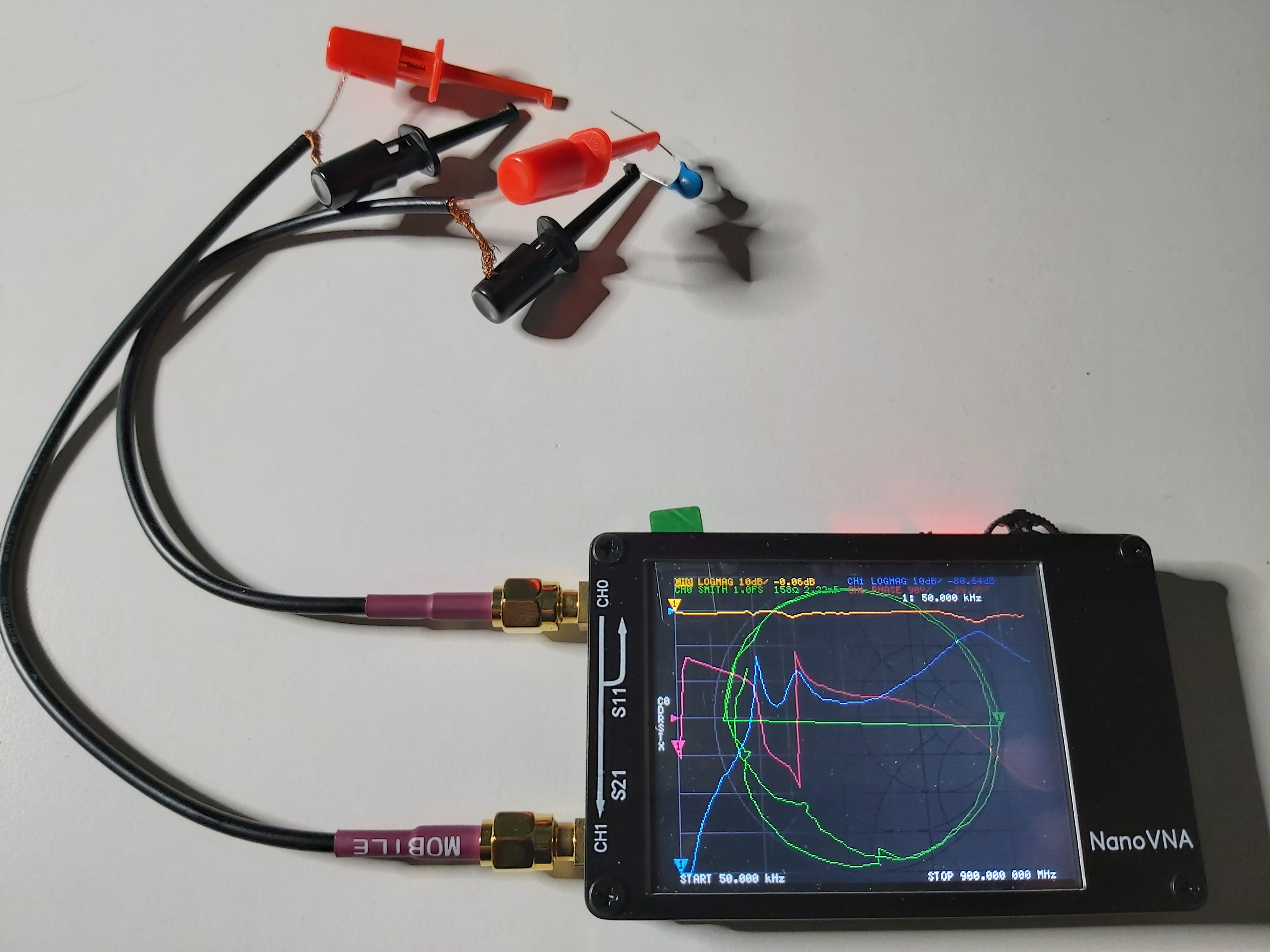
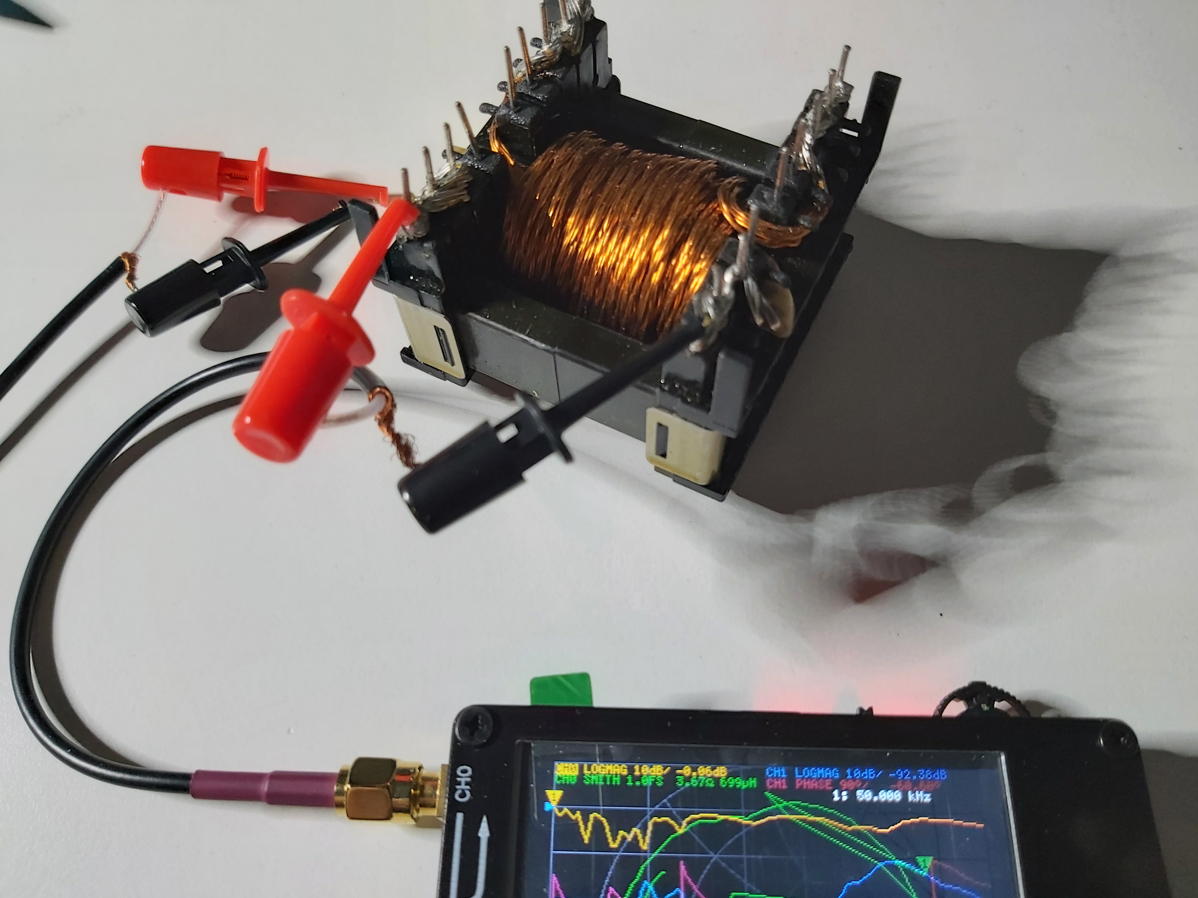
But over last few years, cheap VNAs have come to the market. One of the most commonly used hobbyist budget VNA is called NanoVNA, which is available on many version starting at well below 100 US dollars. You can use such a Vector Network Analyzer (VNA) to measure and understand RLC parasitics in radio / wireless design and construction. it can be used to measure resistors, capacitors, and inductors and their non-ideal behaviors at radio and even microwave frequencies. I have tested first NanoVNA and S-A-A-2 NanoVNA V2. I found both to be useful for measuring RLC values in RF circuits (meaning quite low inductance and capacitance values).
Here are links to a few videos how to do RLC measurements with NanoVNA:
NanoVNA – Measuring RLC Components
nanoVNA – Measuring Inductors and Capacitors (Vers. 3)
Using a nanoVNA to determine unknown inductance value
Keep in mind that NanoVNA uses RF frequencies to measure the RLC components. The shunt method is most accurate within a range of impedances or capacitance. The impedance seen by VNA is a function of frequency, thus as the frequency of measurement moves further away from the ideal the measurement will be less and less accurate. This is one reason (not the only reason) the observed inductance changes as you go up in frequency. Stray capacitance in the test fixture, between the coils of the inductor, as well as proximity effect and skin effect… all of these things are frequency dependant and will play a role in determining the behaviour of your inductor at different frequencies while being measured with the nanoVNA. If one wishes to simply obtain a “marked value” measurement of a given inductor, a relatively crude test fixture can work.
For accurate result it is best to perform the characterization the component at the frequency the component is designed to be used, user proper test jug and do good calibration of VNA. It all depends on what your goals are.
28 Comments
Tomi Engdahl says:
NanoVNA – Measuring RLC Components
https://www.youtube.com/watch?v=R0mRTigYzco
Using a Vector Network Analyzer (VNA) to measure and understand RLC parasitics in radio / wireless design and construction. Looks at resistors, capacitors, and inductors and their non-ideal behaviors at radio and microwave frequencies. Also includes brief discussions of EM fields, both in free space and around circuit components.
Tomi Engdahl says:
Inductance measurements results with Multi component testers
Small common mode choke (ferrite core):
1.39 mH result
Turn around get first 1.20 mH, then next measurement same direction 1.39 mH
Turn around again gets 1.20 mH and then 1.38 mH
Mains transformer low voltage coil 246 mH
Turn around 158 mH and next measurement same direction 234 mH
Tunr aroun 169 mH and next 245 mH
Another signal transformer 0.53 mH
Other way 0.52 mH next 0.53 mH
Claerity AI says:
The pandemic has entirely changed the way of working. Most of us work with common web conferencing software like Google Meet, Microsoft Teams, and Zoom to discuss the project. During the conference call, you may face external challenges like noise distortion, network connectivity, communication lag, and other background noises. For getting rid of the background trouble during your conference call, you can use the background noise removal app for better sound quality.
Tomi Engdahl says:
https://www.edaboard.com/threads/measuring-inductance-with-network-analyser.73955/
Hi cat
It is easy enough to get a reasonable measurement of inductance using a network ananlyser.
You will need an open ended coax lead with a connector to fit your network analyser.
Make sure that the open end is large enough to connect your inductor.
Connect the lead to Port 1 and set measurement to S11, probably the reset condition.
Set the frequency range to 10 – 20MHz, or what ever you feel most suitable.
Select Smith chart and turn the marker on, set to your desired frequency.
Short circuit the open end of the coax in the same way as it will be when connected to your inductor.
Normalise the display, Data to Memory & Data/Memeory on the HP8753.
Add a phase offset of 180 degrees.
The marker should now show an open circuit or close to.
Connect you inductor in place of the short.
Read off the inductance from the marker.
Different analysers may disply the answer differently the 8753 reads inductance and capacitance directly. You may have to work it out from the reactance if that is al that is displayed.
Tomi Engdahl says:
Measuring Capacitor Parameters Using Vector Network Analyzers
https://www.researchgate.net/publication/269166796_Measuring_Capacitor_Parameters_Using_Vector_Network_Analyzers
Fig. 3. Two terminal passive components measueremnt techniques using
VNA: (a) reflection technique; (b) shunt-through technique; (c) series
through technique.
V. CONCLUSION
Vector network analyzers can be very useful for accurate
capacitor impedance, resonant frequency, capacitance and ESL
measurements in broad frequency range if proper measurement
technique and de-embedding is used. Measurement accuracy of
several % and even lower can be achieved using proper
measurement technique. Measurement error of capacitors
impedance and ESR depends not only on capacitor impedance
magnitude (and frequency) but also on the measurement
technique used.
The best suited technique for capacitor fres measurement is
the shunt-through technique, because measurement accuracy of
capacitor impedance at fres and in the vicinity of it is very good
(even below 1%) and this technique is less sensitive to the
experimental setup parasitics. For capacitor impedance
measurements in broad frequency range (when capacitor |Zc|
can change from mΩ to kΩ) it is better to use combination of
the shunt-through and series-through techniques: when |Zc| is
below several tens of ohms, then it is better to use shunt-
through technique; when |Zc| is above several tens of ohms,
then it is better to use series-through technique. The reflection
technique should not be used for capacitor parameters
measurements because, firstly, it can give accurate results only
when capacitor |Zc| slightly differs from 50Ω and secondly, it is
very sensitive to uncalibrated connectors parasitics.
The most problematic parameter to measure accurately with
VNA is capacitor ESR. Only shunt-through technique should
be used for accurate ESR measurements. However there are
some limitations. ESR can accurately be measured only at fres
and in vicinity of it (ESR measurement error below 3% can be
achieved). For frequencies which are much higher or lower
than fres the measurement accuracy can be very poor, even
using shunt-through technique, because when capacitor
reactance is much higher than its ESR, then the measurement
error can increase enormously. Accurate measurements of ESR
of capacitors with C lower than several tens of nF are
impossible. ESR measurements of small-capacitance
capacitors using VNA is completely useless.
Overall it can be concluded that VNA can substitute more-
expensive impedance analyzers for accurate capacitor
parameters measurements in broad frequency range with some
limitations in terms of ESR measurements.
Claerity AI says:
The pandemic has entirely changed the way of working. Most of us work with common web conferencing software like Google Meet, Microsoft Teams, and Zoom to discuss the project. During the conference call, you may face external challenges like noise distortion, network connectivity, communication lag, and other background noises. For getting rid of the background trouble during your conference call, you can use the background noise removal app for better sound quality.
Tomi Engdahl says:
DIY transformer/inductor tester
https://www.youtube.com/watch?v=QBbEYYWiBI8
Shorted transformer hard to tell? Let’s build a tester of transformers and inductors. It can identify shorted windings, including just 1 short turn. It’s hard to test switching transformers and inductors for internal shorts using any other tool. This tool is very useful, especially when fixing switching power supplies and inverters. It’s a simple ring tester, testing the winding based on the number of damped oscillations it can make. An internal short will turn a high Q factor transformer or inductor into a very low Q one, resulting in way less damped oscillations (rings). The Q factor is affected by the internal short turns way more than the inductance is.
Tomi Engdahl says:
Transformer / inductor tester
http://danyk.cz/avr_ring_en.html
https://www.youtube.com/watch?v=QBbEYYWiBI8&t=2s
Tomi Engdahl says:
NanoVNA Sorts Unknown Ferrite Suppression Beads
https://m.youtube.com/watch?v=KmKQibSDzqM
Because suppression ferrites aren’t marked, its difficult to know what frequencies they work on. Now you can use the popular NanoVNA along with free software to graph the unknown ferrite’s impedance over frequency.
Tomi Engdahl says:
#135: Measure Capacitor ESR with an Oscilloscope and Function Generator
https://www.youtube.com/watch?v=115erzCCxgE
This video discusses how to measure the ESR (equivalent series resistance) of a capacitor using an oscilloscope and function generator. All of the capacitors tested in this video were 220uF electrolytic caps. In reality, the resistance in the plates of a dried out electrolytic capacitor can’t be modeled as a simple series resistor, but for the purposes of identifying good from bad, this simplification works fine. In the video, I show the ESR meter that I made in 2006. The video for that is here:
https://www.youtube.com/watch?v=bmYAgat-sOQ
A copy of the video notes can be found here:
https://www.qsl.net/w/w2aew//youtube/Measuring_capacitor_ESR.pdf
Tomi Engdahl says:
#56: Basics of Capacitor & Inductor self-resonance, parasitics, etc. – Tutorial
https://www.youtube.com/watch?v=vi24SpKYYoQ
Tomi Engdahl says:
https://www.pcb-hero.com/blogs/lickys-column/inductors-introduction-types-and-applications-analyzed
Tomi Engdahl says:
https://www.electricaltechnology.org/2022/01/inductor-color-codes.html
Tomi Engdahl says:
#346: Basics of Capacitor Leakage / using the Antique Wireless Association DC Leakage Tester
https://m.youtube.com/watch?v=3o9FncDRPPg&feature=share
This video discusses the basics of capacitor leakage, and how to test for it – focusing on the DC Leakage Tester available as a circuit board from the Antique Wireless Association.
Tomi Engdahl says:
I built capacitance meters using two 555 timers,
use a DMM as the display. Good down to 0.1pF resolution:
https://hackaday.io/project/183405-dual-tlc555-capacitance-meter-01pf-resolution
Tomi Engdahl says:
Bizarre Circuit Tests Capacitors with RF!
https://www.youtube.com/watch?v=yLr16NJ2Llg
This interesting circuit uses 40 MHz RF, to verify capacitors “in circuit,” and has no DC power supply! This PACO C-25 capacitor tester is a very neat design that uses a minimalist approach to get the job done.
Tomi Engdahl says:
Which Capacitor Tester Should I Buy?
https://www.youtube.com/watch?v=lLQThhf3Brc
Learn which Capacitor Tester’s are the best for you. See some example tests as well.
Tomi Engdahl says:
EEVblog 1473 – How Your LCR Meter Works
https://www.youtube.com/watch?v=D9J-AmCcf4U
EEVblog 1474 – Can You Measure Capacitors IN Circuit?
https://www.youtube.com/watch?v=Uds-wLoaZmA
Can you measure capacitors in-circuit with an LCR meter?
Viewer comments:
In circuit testing (passive and active) combined with a good understanding of the circuits purpose and together with a creative mind and coupled with experience can yield excellent results. I have to say you have done an excellent job putting this all together.
Sort of on topic.. I used to test in circuit resistors by measuring them – if the resistance was higher then the stated value it was defiantly bad. But if it was the same or below the resistor was probably good.
As an onsite electrician that insists on repairing every electronic circuit that fails, I found this interesting. Wasn’t familiar with this technique, might have to buy the meter!
This gives me a clue why my LCR meter shows, sometimes, extra more for slightly bad caps..
Never thought about connecting a scope to LCR for visualization.. Now my today’s mission is to do that at lab..
I have a little yellow kidney-shaped LCR meter (Atlas LCR40.) and it only has automatic mode. EG, when measuring a cap it starts with DC. Big electrolytics get measured by rise time. If the cap is smaller it will move on to a 200Hz sine wave. After that it will try 16kHz, and finally 200kHz for the smallest caps. It applies these test tones in bursts, and the final measurement is made with an average of about twenty bursts.
I use a curve/signature tracer to see whether the component actually works at all, and desolder at least one end when doing the measurement.
Are the LCR meters adding a DC bias voltage to avoid reverse biasing electrolytic capacitors? Seems a bit odd that you could take a symmetric waveform and feed it to an electrolytic with impunity.
Unbiased electrolytic caps work Ok with low amplitude AC signals.
In circuit ESR testing cannot be understated.
Tomi Engdahl says:
Inductor Tester
https://www.youtube.com/watch?v=IRRF1FadkFw
In this video i show how to build a circuit that can measure the value of an inductor in conjunction with an oscilloscope. This is meant to be a replacement for my $10 LCR meter, which isn’t very accurate, and has very poor resolution below ~1mH of inductance.
The circuit works by sending a single pulse through an inductor, which has a known capacitance in parallel with it. When current through the inductor is shut off, the L-C pair “rings” at its resonant frequency, determined by f = 1/[2pi*sqrt(LC)]. Since frequency “F” and capacitance “C” are known, the inductance can be determined.
Current through the inductor under test is limited by current limiting resistor(s), which are manually configured by toggle switches. By default, a 680 ohm resistor is connected in series with the inductor, but 220, 100, and 10 ohm resistors can be toggled as well to allow more current for the test pulse. This is because smaller inductor values need to be pulsed with a larger current to generate a readable “ringing” signal, due to their lower energy storage for a given current.
Tomi Engdahl says:
How to Test Inductor Cores.
https://www.youtube.com/watch?v=kHcMO2SGqis
A simple test to find the magnetic permeability of an inductor core. Using an inductance meter, and a known piece of wire. I am using Ferrite toroids as a control, For my needs I just want to know if the core is better or worse than ferrite. If its better, by what kind of margin.
Findings from today’s testing. All the cores shown, except the dark green ones, where about half to a quarter of the premeability of ferrite. The Dark green was a clear winner. As shown in the video. The Green cores, found with bifilar windings in computer power supply units (Usually 2 per PSU), have a premeability around 40 times that of ferrite (probably Metglas). I also found a pale gray one, that appears to be an air core at first glance and its light weight, but stuck to a magnet, which tested at 70µH, about 4 times the premeability of ferrite.
Electronics tutorial – Ferrite and Magnetic permeability
https://www.youtube.com/watch?v=-EqmJx4rJTc
Tomi Engdahl says:
The Great Resistor Embiggens The Smallest Value
https://hackaday.com/2022/11/05/the-great-resistor/
With surface-mount components quickly becoming the norm, even for homebrew hardware, the resistor color-code can sometimes feel a bit old-hat. However, anybody who has ever tried to identify a random through-hole resistor from a pile of assorted values will know that it’s still a handy skill to have up your sleeve. With this in mind, [j] decided to super-size the color-code with “The Great Resistor”.
Resistor color code from Wikipedia with white background
How the resistor color-code bands work
At the heart of the project is an Arduino Nano clone and a potential divider that measures the resistance of the test resistor against a known fixed value. Using the 16-bit ADC, the range of measurable values is theoretically 0 Ω to 15 MΩ, but there are some remaining issues with electrical noise that currently limit the practical range to between 100 Ω and 2 MΩ.
The Great Resistor
This device magnifies the color-code of your resistor
https://hackaday.io/project/188104-the-great-resistor
Tomi Engdahl says:
https://www.perel.fi/tuotteet/73211705/lcr-mittari-bk-precision-bk879b
Tomi Engdahl says:
How to measure a coil with an oscilloscope
https://www.youtube.com/watch?v=GMPmp8rpmsk
Tomi Engdahl says:
#90: Measure Capacitors and Inductors with an Oscilloscope and some basic parts
https://www.youtube.com/watch?v=74fz9iwZ_sM
Tomi Engdahl says:
#83 LCR’s meter D, Q, Phi, ESR what is it all about demonstrated on DER EE DE-5000
https://www.youtube.com/watch?v=ivVSq0IiZGo
Tomi Engdahl says:
Understanding LCR Meters
https://www.youtube.com/watch?v=vi9t5gdog7Q
This video provides a brief technical introduction to LCR meters and how they are used to make different types of measurements.
Learn more about the R&S LCX LCR meter: http://rsna.us/6052wgG3q
Timeline:
00:00 Introduction
00:12 Fundamental electronic building blocks
00:34 A brief refresher on impedance
01:27 Measuring inductance (L), capacitance (C), and resistance (R)
02:10 About traditional LCR bridges
02:39 About phase shifts
03:18 About LCR meters
04:03 Phase angle and loss angle
05:16 About Q (quality factor)
06:02 Transformer testing
06:52 Making measurements with LCR meters
07:07 Connections / test fixtures / corrections
08:00 About Kelvin (4-wire) measurements
08:58 Series vs. parallel models
09:41 Measurement frequency
10:26 Measurement level
10:54 Bias
11:35 Summary
Tomi Engdahl says:
UNI-T UT622A UT622C UT622E Digital Capacimeter LCR Meter Capacitor Electronic Components Tester Multimeter
https://www.aliexpress.com/item/1005004328518229.html?spm=a2g0o.detail.0.0.4276KE1bKE1beJ&gps-id=pcDetailTopMoreOtherSeller&scm=1007.40000.327270.0&scm_id=1007.40000.327270.0&scm-url=1007.40000.327270.0&pvid=44fbe907-0661-44a4-b3bf-634cddf021f4&_t=gps-id:pcDetailTopMoreOtherSeller,scm-url:1007.40000.327270.0,pvid:44fbe907-0661-44a4-b3bf-634cddf021f4,tpp_buckets:668%232846%238111%231996&pdp_npi=4%40dis%21EUR%2174.42%2137.21%21%21%2176.09%21%21%402103253416964198296474285efa52%2112000028773692182%21rec%21FI%212528467667%21&search_p4p_id=202310040443496825891926344999820974_9
Tomi Engdahl says:
https://www.voltech.com/products/dc1000a-25a-dc-bias-supply/