In this post I am talking about adapting 10 and 100 megabit twisted pair Ethernet to use coaxial cable instead of twisted pair wiring. Those 10BASE-T and 100BASE-TX Ethernet st standards use two wire pairs for communications (one for TX and other for RX). In this article I am describing how to adapt them to use coaxial cables. I got the idea for this posting when I read discussion at https://superuser.com/questions/1236350/ethernet-cable-connections-from-coaxial-cables
The presented ideas are not directly adaptable to faster twisted pair wiring Ethernet standards (1G, 10G etc.) because they use all the four wire pairs for communicating at both directions.
First start with the standards.
IEEE 802.3i standard (1990) defines 10BASE-T 10 Mb/s twisted pair Ethernet communications.
A 10BASE-T transmitter sends two differential voltages, +2.5 V or −2.5 V. Typically 10BaseT transmitters built so that they inject current to line and receivers sense received voltage. The signal bandwidth is 10 MHz.
IEEE 802.3u standard (1995) defines 100BASE-T Fast Ethernet that works on 100 Mb/s speed. A 100BASE-TX transmitter sends three differential voltages, +1 V, 0 V, or −1 V. The signal has most energy at bandwidth of 31.25 MHz, but there are some signal components that the signal occupies a very broad frequency range up to over 100 MHz.
100BASE-TX and 1000BASE-T were both designed to require a minimum of category 5 cable and also specify a maximum cable length of 100 metres (330 ft). Category 5 cable has since been deprecated and new installations use Category 5e or 6. 10BASE-T and 100BASE-TX require only two pairs (pins 1–2, 3–6) to operate. The cable is specified to have differential impedance from 85 to 115 ohms. The cable is designed to have low cross-talk by twisting the pairs to cancel interference. 100BASE-TX follows the same wiring patterns as 10BASE-T, but is more sensitive to wire quality and length, due to the higher bit rates.
Twisted pair to 75 ohm coax with video baluns
Twisted pair Ethernet is designed for 85 to 115 ohms impedance twisted pair. Having a cable that is nicely balanced and has a tight twist rate helps in overall performance of the cable. What I am aiming to do it transfer the signal over 75 ohms coaxial cable (unbalancaed media). RG59 with both solid center conductor (RG59B/U) and stranded center conductor (RG59A/U) as well as RG6 are 75 ohm coaxial cables often found in video applications and installed to building.
To get the Ethernet signal from twisted pair to coax and back would need to adapt both impedance and balanced/unbalanced nature of signal). Fortunately there are widely available cheap tools designed for this: Traditionally analogue video transmission is done using 75 ohm coaxial cables. Those video signals are not directly compatible with nowadays more widely used twisted pair wiring (CAT5, CAT6 etc..), which means you just can’t wire the signals directly form video output to a twisted pair wire and get good results. Video signal can be adapted to UTP wiring using a video balun between BNC video connector and the twisted pair wiring.
To do the do balanced-unbalanced conversion with impedance is to put some suitable balun transformer between Ethernet card and coax cable. Many passive Video baluns originally designed to interface 75 ohms coax video signal to 100 ohms UTP cable on the “wrong way”.
It depends on the video balun construction how well they work with Ethernet signals. with 10M Ethernet it is expected that quite many video baluns would work as the frequency range used fits quite close to typical video signal range (up to 6-10 MHz).
With 100M there is higher frequencies up to around 30 MHz, so baluns that are limited to 10 MHz or lower might not work acceptably, but baluns that advertise HD resolutions support work with higher bandwidth signals can work up to 30 Mhz to almost 100 MHz depending on balun design and construction quality.
Here is my experiment with two cheap “no name Chinese” video baluns connected to around 16 meters of 75 ohms antenna coaxial cable. For my testing I connected two baluns to the ends of coaxial cables and RJ-45 connector one wire pair carrying the signal (pins 1 and 2) and let the other pair (pins 3 and 6) go straight through normally.
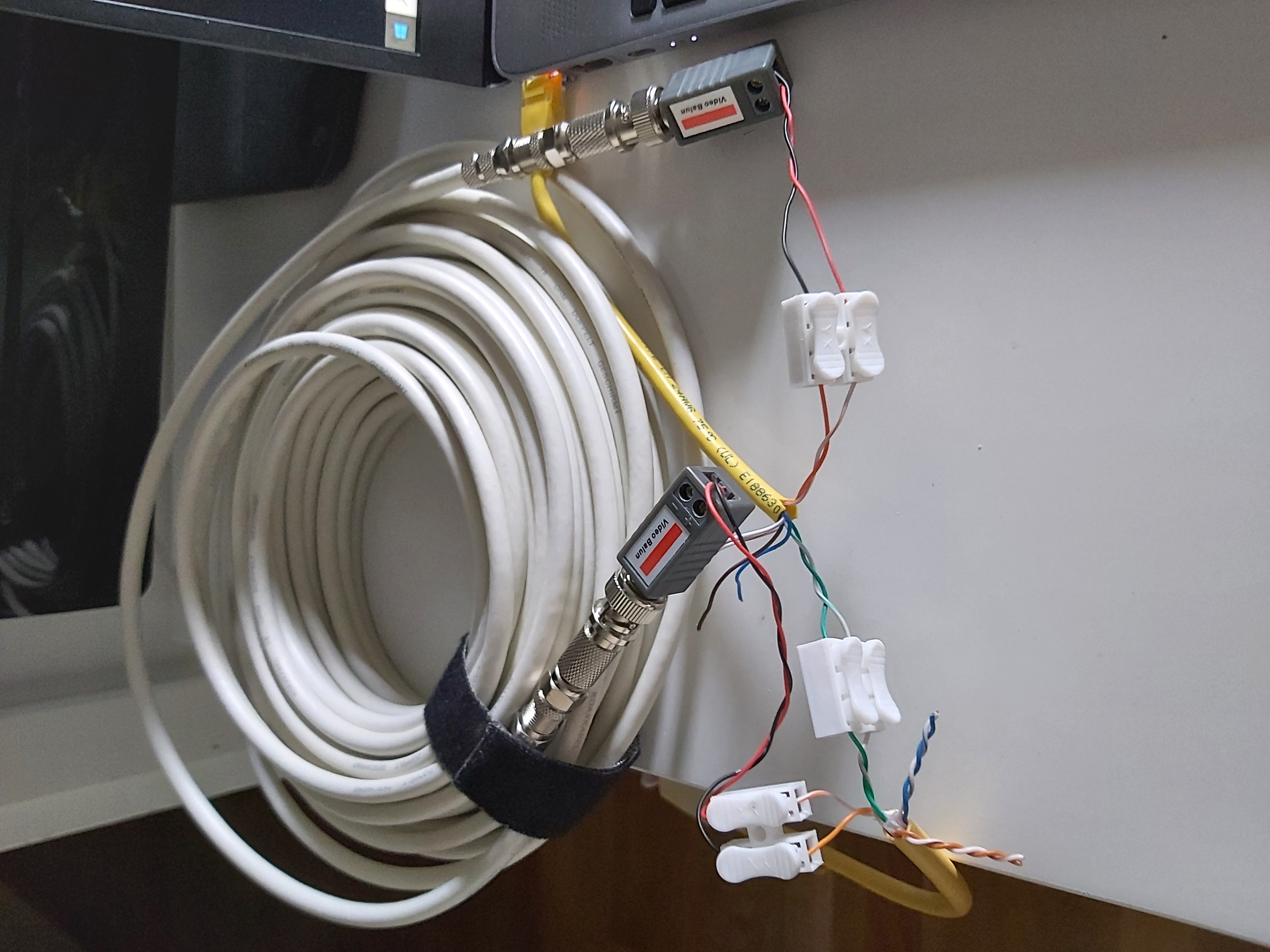
Because this was just for test purposes, I did the adaptation for only one data direction of Ethernet connection. The Ethernet connection seems to work well without problems. For a real-life applications, I would need to have another coaxial cable and two baluns for that to let all the signals to go through coaxial cable. This proof of concept worked at this cable length at 10 and 100 megabits per seconds speeds without noticeable issues.
To carry the signals you would need two 75 ohms coax cables (one for RX and other for TX) and four baluns. In 100 Mbit ethernet over cat5 cable, there actually is a dedicated
transmit and receive. So you can’t easily replace both with a single piece of coax.
G.703/G.704 impedance matching baluns do not work for Ethernet
Several manufacturers make promising looking baluns 75 120 ohm are used for G.703/G.704 impedance matching purposes. They have two coaxial connectors and one RJ-45

This type of connectors are designed for international WAN environments. Specifically created for the ITU-T/CCITT G.703 TELECOM applications, the balun provides conversion between 75 Ohm and 120 Ohm G. 703 interfaces. Typically this type of adapters support data rate up to 2.048 Mbps (E1) and some promise also support for 8 Mbps. For those of you who may not be familiar with G. 703, it is similar to T1 or DDS standards in the USA. This interface standard is used throughout the world to specify the physical and electrical characteristics which enable the interconnection of digital network components. For example G703 is the connection standard for E1 services in Europe. This balun simply converts 75 Ohm G. 703 transmit signals to 120 Ohm signals for transmission over network, or reception by a CPE. Many adapters list that the twisted pair side can be 120 ohms or 100 ohms impedance.
This type of adapters come depending on manufacturers and models with two different pin-outs on RJ-45 side: (1,2,4,5) or (5,4,6,3). Neither of those pin-outs match the pins used by 10/100M Ethernet (1,2,3,6). Other issue is that the bandwidth of many of products is advertised to be 2.048 Mbit/s, so most probably they might not perform well at 10 MHz (for 10 Mbit/Us Ethernet) or at 32 MHz (100 Mbit/s Ethernet). I have not tested, but I think that the adapters that are designed to support also 8 Mbit/s data speed, could work somehow at 10 Mbit/s speed if you build a custom RJ-45 cable that adapts the Ethernet pinout to data pin pinpout used by the balun.

Information sources:
https://www.ad-net.com.tw/all-about-impedance-converters/
https://www.alibaba.com/product-detail/G703-Balun-75-Ohm-to-120_60301276025.html
https://www.temple-star.com/ITU_T_CCITT_G703_Telecom_Balun.htm
https://www.alibaba.com/product-detail/16-Channels-75-Ohm-BNC-To_60386281089.html
https://cables24.com/en/coaxial/balun/balun-module/1241-balun-75-120-ohmrj-45-female-dual-bnc-female-g-703-e1-e3
http://www.e1-converter.com/G703_Balun/75_ohm_to_120_ohm_Coax_to_RJ45_Balun_Panel.html
Experimenting with 75 ohms cable without baluns
The next question for experimenting was could this work even without baluns? I have earlier tested that Ethernet can run somewhat outside that 85-115 ohms impedance in many cases OK. I tested Ethernet to work in the range 75-80 ohms on my earlier tests. So the 75 ohms coax impedance could be “close enough” as such. So it might work if you are lucky at 75 ohms impedance many coax cables have close enough impedance for 10/100 M Ethernet. To carry the signals you would need two 75 ohms coax cables (one for RX and other for TX).
Connecting the signal to coax cable has it’s challenges, because Ethernet cards are designed to drive balanced wire pairs, while coaxial cable is unbalanced. To do this adaptation correctly, a balun should be used.
But on some cases could could live without balun. Ethernet interfaces use transformer isolation for transmitted and received signals, and in most cases the line side coils are “floating”. In such case a direct connection to unbalanced coaxial cable could work (but it is not guaranteed to work always, because there are cards where the line side coils have center taps that can be connected to termination resistors and/or power-over-ethernet electronics). Those with Ethernet transformer line side coil grounded in some way (typical especially in PoE systems), trying to drive coaxial cable is expected pretty much fail without balun.
On my tests the devices I used had Ethernet transformer output coils completely floating, and worked OK when connected to coaxial cable. Here is picture of my experimenting with the same 16 meter coaxial cable where I directly connected the Ethernet card to coaxial cable directly in the same way where I earlier used video baluns.
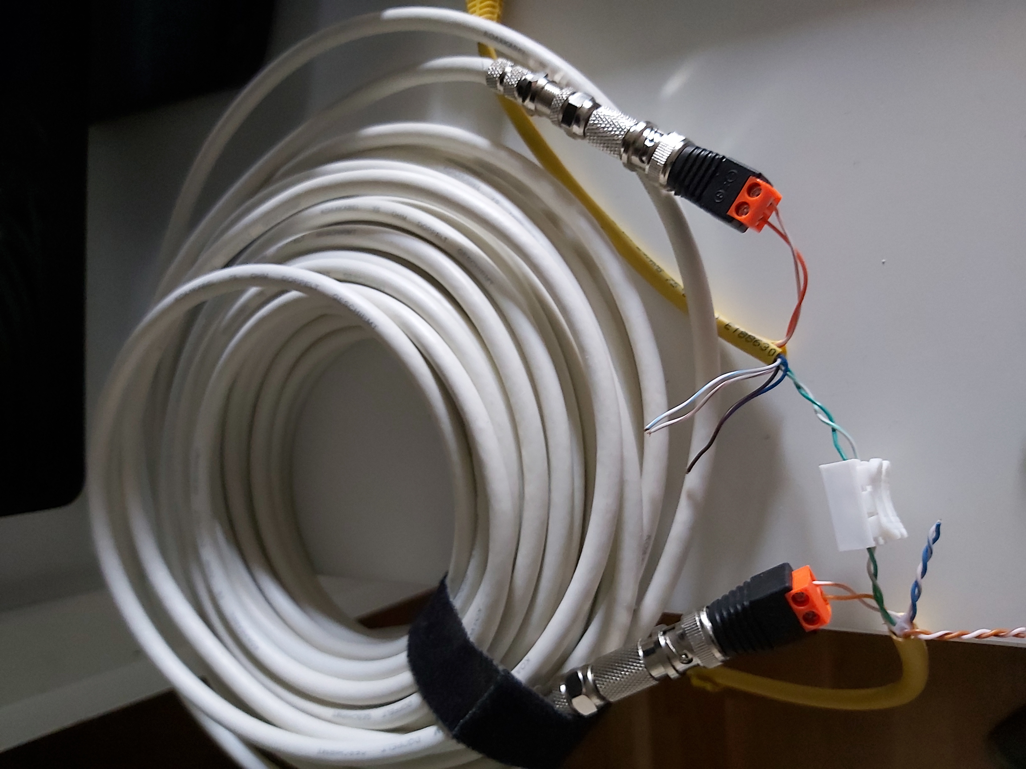
The Ethernet signal seemed still work OK on short test.
Commercial converters for one 75 ohm coax
There are also commercially made Ethernet to 75 ohm coax cable converters designed for video surveillance applications. Video surveillance systems have traditionally used 75 ohms coaxial cable to carry analogue (and later in some cases digital) video signal from camera to surveillance center. When IP based digital cameras have become popular, there has been interest to run Ethernet signal over single 75 ohm coaxial cable from surveillance center to the IP camera.
It is not physically impossible to send data over a single cable in both directions at the same time. There are many communications systems that do that (PSTN, gigabit 1000BASE-T, etc.). The challenge is that you need to somehow subtract the local TX contribution to get the RX part. And you have to make sure the TX contribution doesn’t get fouled up by the RX contribution. The problem is that this all has to work with, in the case of 100BaseT, pretty fast rise times. And you need to maintain 75-Ohm termination at both ends.
Usually this is done nowadays using active electronics, but some companies have succeeded to design a multiplexter that does 10base-tx or 100baseT to coax conversion system with passive components only.
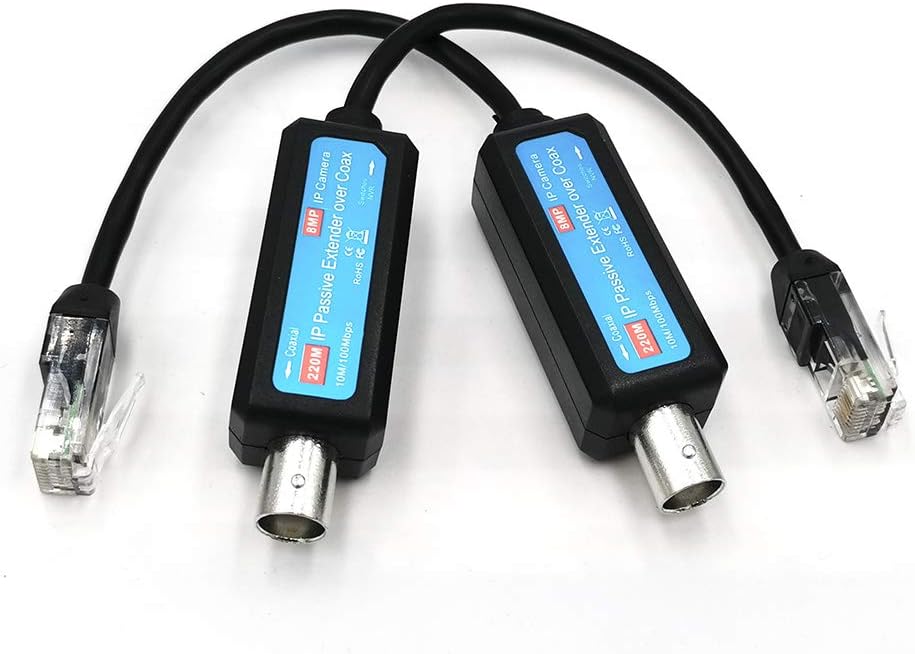
There are several different products marketed for this, some are active devices and some are completely passive devices. For passively adapting 10/100M Ethernet to single 75 ohm coaxial cable, there are product like Monoline Coax Balun – Male BNC to RJ45 jack 10BaseT – 75 Ohm – Each and IP Passive Extender Ethernet Over Coax 1-CH, IP Network to Coaxial Transmitter IP Network Converter Fit CCTV Camera UTP RG59/ RJ45 4-Wired 1236 Cable No. BNC Video Balun Only Fit POE Camera System.
Direct connection to many 50 ohms coax cables
What if we want to connect twisted pair Ethernet to 50 ohms coaxial cable (old Ethernet coax or 50 ohm RF antenna cable)? There are several experimental ways that allows 50 ohms coax to be used on some cases.
You can use two 50 ohm single ended coaxial cables for single 100 ohm differential signal, unless there is something special that prevents it. I have seen many applications where micro-coax is used for differential signals. For example display panels with LVDS or eDP, and a I-PEX VS type connector.
The impedance is depending on the ratio of capacitance and inductance between the two conductors. Two 50 Ω coax to ground in “series” will result in 100 Ω differential impedance (“throug” the ground). The right 100 ohms differential impedance is what Ethernet wants. Both pieces of coax need to be of equal length for this to work. Cat 5 cable is 100 ohms differential, which is exactly what you want. This coaxial solution uses two 50-ohm cables for the two arms of a differential signal, giving 100 ohms differential.
Here are some notes on the impedance from Maxim application note:
As shown in Figure 4, coupled cables (STP, UTP, twinax) derive their differential characteristic impedance both from coupling between the (+) and (-) lines of a pair (Z1), and coupling of each side to ground (Z2, Z3). Any imbalance in a differential pair, such as asymmetry of length, or twist, or dielectric environment (in which Z2 ≠ Z3), causes a differential-to-common-mode conversion with measurable symptoms, such as intrapair skew.

There are some differences on properties. The single-ended impedance seen by Ethernet card is somewhat different with two coax cables approach, but that is not significant issue and devices can live with it. The single-ended properties of each transmission line in a twisted pair are terrible. This is not very controlled impedance. The single-ended impedance of the cable varies down its length, depending on the position of the local conductors. The typical common impedance of an unshielded twisted pair will vary from around 100 Ω to 200 Ω. As long as there are no common signals on the twisted pair, you don’t need to care about the common impedance. The challenge is preventing common signals from getting on the twisted pair.
For more information on impedance matching between coax and twisted pair, check out following links:
https://electronics.stackexchange.com/questions/391254/non-coaxial-50-ohm-cable-for-lvds
https://www.eeweb.com/interfacing-lvds-to-pecl-lvpecl-cml-rs-422-and-single-ended-devices/
https://www.pulseresearchlab.com/pages/necl-pecl-faqs
https://ez.analog.com/clock_and_timing/f/q-a/20074/ad9517-lvpecl-output-interface-to-a-fanout-buffer
If you had four 50 ohms coaxial cables of same length, you could use then to carry one 10/100m Ethernet connection just by wiring the signal carrying pins to the center pins of coaxial cables and connecting the shield of coaxial cables carrying signal together on both ends. In real life applications using four coaxial cables is not usually practical.
50 ohms coax with baluns
The same balun trick that I used with 75 ohm coax can be used with 50 ohms cable. Ideally you should use 50 ohms to 100 ohms baluns, but because they are rarely needed they are usually hard to get and expensive.
For a shortcut test I tried to use 100 ohms to 75 ohms baluns with 50 ohms cable. I found out that 100 ohm to 75 ohm video baluns can also work with 50 ohms cable. I tested with video balun and around 10 meters of RG-58 cable. It worked.
With those 75-100 ohm video baluns when cable is 50 ohms, expect to to get around 75 ohms impedance on twisted pair cable instead of correct 100 ohms. It was not entirely correct, but was still close enough that it seemed to work. For 10M or 100M two 50 coax cables are needed, one for TX and other for RX. I have not tested how long cable this “hack” can support.
2 Comments
Dan says:
Interesting writeup/test. I am doing something similar for a planned RF over twisted pair product I would like to build. Have you ever seen anything on transmitting cellular band or Wi-Fi signals over twisted pair? Maybe the differences between Cat-5e and Cat-6/6e. I am working on a PoE model over the same cable 2 wires for Tx and RX each and the other four for DC power.
Tomi Engdahl says:
I have seen there are systens that transmit TV antenna cable signals over twisted pair wires. Typically frequencies up to 500 MHz to 1 GHz. Those systems use baluns on both ends of cable and also often suitable amplifier on sending end that boosts higher frequencies more than lower.
Claimed to work well with shielded cables (shielded cat6 or cat7). With unshielded cable more variation with performance.