Venerable Ethernet provides the backbone of the internet. Ethernet has risen to complete dominance for local area networks over its forty years of existence. The first Ethernet experimentals versions started in 1972 (patented 1978). The commercialization of Ethernet started in 1980′s.
At first Ethernet technology remained primarily focused on connecting up systems within a single facility, rather than being called upon for the links between facilities, or the wider Internet. Ethernet at short distances has primarily used copper wiring. Fiber optic connections have also been available for the transmission of Ethernet over considerable distances for nearly two decades.
Today, Ethernet is everywhere. It’s evolved from a 2.93-Mb/s and then 10-Mb/s coax-based technology to one that offers multiple standards using unshielded twisted pair (UTP) and fiber-optic cable with speeds over 100 Gb/s. Ethernet, standardized by the IEEE as “802.3,” now dominates the networking world. And the quest for more variations continues onward.
Ethernet is on the Way to Total Networking Domination. Ethernet is all over the place. Most of us use it day by day. The first coax-primarily based Ethernet LAN conceived in 1973 by Bob Metcalfe and David Boggs. Since then Ethernet has grown to the stage of pretty much entire local area networking goes through it (even most WiFi hot spots are wired with Ethernet). It’s hard to overestimate the importance of Ethernet to networking over the past 25 years, during which we have seen seen Ethernet come to dominate the Networking industry. Ethernet’s future could be even more golden than its past.
Ethernet has pretty much covered office networking and backbones industrial networks. In industrial applications there applications where Ethernet is still coming. Ethernet is on the Way to Total Networking Domination article says that single-pair Ethernet makes possible cloud-to-sensor connections that enable full TCP/IP, and it’s revolutionizing factory automation. This technology will expand the use of Ethernet on the industrial applications. Several different single-pair Ethernet (SPE) standards seeks to wrap up full networking coverage by addressing the Internet of Things (IoT), and specifically the industrial Internet of Things (IIoT) and Industry 4.0 application space.
Traditional copper Ethernet
Started with 50 ohms coax in 1973. In the 1990′s the twisted pair Ethernet with RJ-45 connectors and fiber became the dominant media choices. Modern Ethernet versions use a variety of cable types.
Twisted pair Ethernet mainstream use stared with CAT 5 cable that has been long time used for 100 Mbps or slower plans, while CAT 5a cables and newer are ideal for faster speeds. Both CAT5e and CAT6 can handle speeds of up to 1000 Mbps, or a Gigabit per second.
Today, the most common copper cables are Cat5e, Cat6, and Cat6a. Now twisted pair the main media (CAT 6A, CAT7, CAT8 etc.) can handle speeds from 10M to 10G with mainstream devices, typically up to 100 meters. All those physical layers require a balanced twisted pair with an impedance of 100 Ω. Standard CAT cable has four wire pairs, and different Ethernet standards use two of them (10BASE-T, 100BASE-TX) or all four pairs (1000BASE-T and faster).
Many different modes of operations (10BASE-T half-duplex, 10BASE-T full-duplex, 100BASE-TX half-duplex, etc.) exist for Ethernet over twisted pair, and most network adapters are capable of different modes of operation. Autonegotiation is required in order to make a working 1000BASE-T connection. Ethernet over twisted-pair standards up through Gigabit Ethernet define both full-duplex and half-duplex communication. However, half-duplex operation for gigabit speed is not supported by any existing hardware.
In the past, enterprise networks used 1000BASE-T Ethernet at the access layer for 1 Gb/s connectivity over typically Cat5e or Cat6 cables. But the advent of Wi-Fi 6 (IEEE 802.11ax) wireless access points has triggered a dire need for faster uplink rates between those access points and wiring closet switches preferably using existing Cat5e or Cat6 cables. As a result, the IEEE specified a new transceiver technology under the auspices of the 802.3bz standard, which addresses these needs. The industry adopted the nickname “mGig,” or multi-Gigabit, to designate those physical-layer (PHY) devices that conform to 802.3bz (capable of 2.5 Gb/s and 5 Gb/s) and 802.3an (10 Gb/s). mGig transceivers fill a growing requirement for higher-speed networking using incumbent unshielded twisted-pair copper cabling. The proliferation of mGig transceivers, which provide Ethernet connectivity with data rates beyond 1 Gb/s over unshielded copper wires, has brought with it a new danger: interference from radio-frequency emitters that can distort and degrade data-transmission fidelity.
CAT8 can go even higher speeds up to 40G up to 30 meters. Category 8, or just Cat8, is the latest IEEE standard in copper Ethernet cable. Cat8 is the fastest Ethernet cable yet. Cat8 support of bandwidth up to 2 GHz (four times more than standard Cat6a bandwidth) and data transfer speed of up to 40 Gbps. Cat 8 cable is built using a shielded or shielded twisted pair (STP) construction where each of the wire pairs is separately shielded. Shielded foil twisted pair (S/FTP) construction includes shielding around each pair of wires within the cable to reduce near-end crosstalk (NEXT) and braiding around the group of pairs to minimize EMI/RFI line noise in crowded network installations. Cat 8 Ethernet cable is ideal for switch to switch communications in data centers and server rooms, where 25GBase‑T and 40GBase‑T networks are common. Its RJ45 ends will connect standard network equipment like switches and routers. Cat8 cable supports Power over Ethernet (PoE) technology. Cat8 is designed for a maximum range of 98 ft (30 m). If you want fater speeds and/or long distance there are various fiber interfaces.
Power over Ethernet
Power over Ethernet (PoE) offers convenience, flexibility, and enhanced management capabilities by enabling power to be delivered over the same CAT5 or higher capacity cabling as data. PoE technology is especially useful for powering IP telephones, wireless LAN access points, cameras with pan tilt and zoom (PTZ), remote Ethernet switches, embedded computers, thin clients and LCDs.
The original IEEE 802.3af-2003 PoE standard provides up to 15.4 W of DC power (minimum 44 V DC and 350 mA) supplied to each device. The IEEE standard for PoE requires Category 5 cable or higher (can operate with category 3 cable for low power levels). The updated IEEE 802.3at-2009 PoE standard also known as PoE+ or PoE plus, provides up to 25.5 W (30W) of power.
IEEE 802.3bt is the 100W Power over Ethernet (PoE) standard. IEEE 802.3bt calls for two power variants: Type 3 (60W) and Type 4 (100W). This means that you can now carry close to 100W of electricity over a single cable to power devices. IEEE 802.3bt takes advantage of all four pairs in a 4-pair cable, spreading current flow out among them. Power is transmitted along with data, and is compatible with data rates of up to 10GBASE-T.
Advocates of PoE expect PoE to become a global long term DC power cabling standard and replace a multiplicity of individual AC adapters, which cannot be easily centrally managed. Critics of this approach argue that PoE is inherently less efficient than AC power due to the lower voltage, and this is made worse by the thin conductors of Ethernet.
Cat5e cables usually run between 24 and 26 AWG, while Cat6, and Cat6A usually run between 22 and 26 AWG. When shopping for Cat5e, Cat6, or Cat6a network cables, you might notice an AWG description printed on the cable jacket such as: 28AWG, 26 AWG, or 24AWG. AWG stands for American wire gauge, a system for defining the diameter of the conductors of a wire which makes up a cable. The larger the wire gauge number, the thinner the wire and the smaller the diameter.
One of the newest types of Ethernet cables on the market, Slim Run Patch Cables, actually have a 28 AWG wire. This allows these patch cords to be at least 25% smaller in diameter, than standard Cat5e, Cat6, and Cat6a Ethernet. Smaller cable diameter is beneficial for high-density networks and data centers.
The downside of 28 AWG cable is higher resistance and power loss in PoE applications. Before February 2019, the short answer to “Can 28 AWG patch cords be used in PoE applications?” was “no.” Today, however, the answer is “yes”! 28 AWG patch cords can now be used to support power delivery.
It has been approved that 28 AWG cables can support power delivery and higher PoE levels with enough airflow around the cable. According to TSB-184-A-1, an addendum to TSB-184-A: 28 AWG patch cabling can support today’s higher PoE levels, up to 60W.
To maintain recommendations for temperature rise, 28 AWG cables must be grouped into small bundles. By keeping 28 AWG PoE patch cords in bundles of 12 or less, the impacts of cable temperature rise are diminished thus allowing you to stay within the suggested maximum temperature rise of 15 degrees Celsius. Per TSB-184-A-1, an addendum to TSB-184-A: 28 AWG in bundles of up to 12 can be used for PoE applications up to 30W.In PoE applications using between 30W and 60W of power, spacing of 1.5 inches between bundles of 12 cables is recommended. Anything above 60W with 28 AWG cable requires authorization from the authority in USA.
Single pair Ethernet
Several different single-pair Ethernet (SPE) standards seeks to wrap up full networking coverage by addressing the Internet of Things (IoT), and specifically the industrial Internet of Things (IIoT) and Industry 4.0 application space.
Single Pair Ethernet, or SPE, is the use of two copper wires that can transmit data at speeds of up to 1 Gb/s over short distances. In addition to data transfer, SPE has option to simultaneously delivering Power over Dataline (PoDl). This could be a major step forward in factory automation, building automation, the rise of smart cars, and railways. Single-pair Ethernet (SPE) allows legacy industrial networks to migrate to Ethernet network technology whilst delivering power and data to and from edge devices.
Traditional computer-oriented Ethernet comes normally in two and four-pair variants. Different variants of Ethernet are the most common industrial link protocols. Until now, they have required 4 or 8 wires, but the SPE link is allows using only two wire pairs. Using only two wire pairs can simplify the wiring and can allow reusing some old industrial wiring for Ethernet application. SPE offers additional benefits such as lighter and more flexible cables. Their space requirements and assembly costs are lower than with traditional Ethernet wiring. Those are the reasons why the technology is of interest to many.
The 10BASE-T1, 100BASE-T1 and 1000BASE-T1 single-pair Ethernet physical layers are intended for industrial and automotive applications or as optional data channels in other interconnect applications.
Automotive Ethernet, called 802.3bw or 100BASE-T1, that adapts Ethernet to the hostile automotive environment with a single pair.
There is also a long distance 10BASE-T1L standard that can support distance up to one one kilometer at 10-Mb/s speed. In building automation, long reach is often needed for HVAC, fire safety, and equipment like elevators. The 10BASE-T1 standard has two parts. The main offering is 10BASE-T1L, or long reach to 1 km. The connection is point-to-point (p2p) with full-duplex capability. The other is 10BASE-T1S, or short-reach option that provides p2p half-duplex coverage to 25 meters and includes multidrop possibilities.
All those physical layers require a balanced twisted pair with an impedance of 100 Ω. The cable must be capable of transmitting 600 MHz for 1000BASE-T1 and 66 MHz for 100BASE-T1.
Single-pair Ethernet defines its own connectors:
- IEC 63171-1 “LC”: This is a 2-pin connector with a similar locking tab to the modular connector, if thicker.
- IEC 63171-6 “industrial”: This standard defines 5 2-pin connectors that differ in their locking mechanisms and one 4-pin connector with dedicated pins for power. The locking mechanisms range from a metal locking tab to M8 and M12 connectors with screw or push-pull locking. The 4-pin connector is only defined with M8 screw locking.
Fiber Ethernet
When most people think of an Ethernet cable, they probably imagine a copper cable, and that’s because they’ve been around the longest. A more modern take on the Ethernet cable is fiber optic. Instead of depending on electrical currents, fiber optic cables send signals using beams of light, which is much faster. In fact, fiber optic cables can support modern 10Gbps networks with ease. Fiber optic has been option on Ethernet for a long time. Ethernet has been using optical fiber for decades. The first standard was 10 Mbit/s FOIRL in 1987. The currently fastest PHYs run 400 Gbit/s. 800 Gbit/s and 1.6 Tbit/s started development in 2021.
The advantage most often cited for fiber optic cabling – and for very good reason – is bandwidth. Fiber optic Ethernets can easily handle the demands of today’s advanced 10 Gbps networks or 100Gbps, and have the capability of doing much more. Fiber optic cables can run without significant signal loss for distances, from kilometers up to tens of kilometers depending on the fiber type and equipment used.
The cost of fiber has come down drastically in recent years. Fiber optic cable is usually still a little more expensive than copper, but when you factor in everything else involved in installing a network the prices are roughly comparable.
Fiber optics is immune to the electrical interference problems because fiber optic cable doesn’t carry electricity, it carries light. Because fiber optic cables don’t depend on electricity, they’re less susceptible to interference from other devices.
Fiber optic cables are sometimes advertised to be more secure than copper cables because light signals are more difficult to hack. It is true that light signals are slightly more difficult to hack than copper cable signals, but actually they are nowadays well hackable with right tools.
Fiber has won the battle in the backbone networks on long connections, but there is still place for copper on shorter distances Nearly every computer and laptop sold today has a NIC card with a built-in port ready to accept a UTP copper cable, while a potentially expensive converter or fiber card is required to make a fiber optic cable connection.
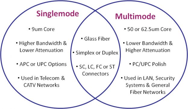
Standard fiber-optic cables have a glass quartz core and cladding. Nowadays, there are two fiber optic cable types widely adopted in the field of data transfer—single mode fiber optic cable and multimode fiber optic cable.
A single-mode optical fiber is a fiber that has a small core, and only allows one mode of light to propagate at a time. So it is generally adapted to high speed, long-distance applications. The core size of single mode fiber has a core diameter between 8 and 10.5 micrometers with and a cladding diameter of 125 micrometers. OS1 and OS2 are standard single-mode optical fiber used with wavelengths 1310 nm and 1550 nm (size 9/125 µm) with a maximum attenuation of 1 dB/km (OS1) and 0.4 dB/km (OS2). SMF is used in long-haul applications with transmission distances of up to 100 km without need a repeater. Typical transmission distances are up 10-40 kilometers. Single mode capable hardware used to be very expensive years ago, but prices for then have came down quicly. Nowadays single mode is very commonly uses.
Multimode optical fiber is a type of optical fiber with a larger core diameter larger (65 or 50 micrometer core) designed to carry multiple light rays, or modes at the same time. It is mostly used for communication over short distances. Multimode Fiber (MMF) uses a core/cladding diameter of typically 50 micrometer/125 mictometer, providing less reach, up to approximately 2 km or less, due to increased dispersion as a result of the larger diameter core.
Depending on your requirements, when going to use fiber, you’re probably first looking for one of these commonly used interfaces: 1000BASE-SX (1 Gbit/s over up to 550 m of OM2 multi-mode fiber), 1000BASE-LX (1 Gbit/s over up to 10 km of single-mode fiber), 10GBASE-SR (10 Gbit/s over up to 400 m of OM4 MMF), 10GBASE-LR (10 Gbit/s over up to 10 km of SMF).
There are many other PHY standards for various data rates and distances, also many common non-standards for even longer distance. The required optical transceivers are usually SFP (1G) or SFP+ modules (10G) plugged into your network hardware. Switches and network adapters with SFP modules allow you to create custom fiber optic high-speed Ethernet networks by plugging in suitable type SFP module. External media converters for devices without SFP slot are also available. A fiber media converter, also known as a fiber to Ethernet converter, allows you to convert typical copper Ethernet cable (e.g., Cat 6a) to fiber and back again.
100G (100 Gb/s) Ethernet has had a good run as the backbone technology behind the cloud, but the industry is moving on. There is expected to be exploding demand for bandwidth in the 5G/mmWave era that’s now upon us. Modern
400G and 800G test platforms validate the cloud’s Ethernet backbone, ensuring support for the massive capacity demands of today and tomorrow. Many service providers and data centers, for various reasons, skipped over 400G Ethernet implementations and are looking toward 800G Ethernet for their next network transport overhaul. Adoption of 400G is still happening, but the growth of 800G will eclipse it before long.
In the future, the speeds of Ethernet networks will increase. Even after the 25, 40, 50 and 100 gigabit versions, more momentum is needed. For example, growing traffic in data centers would require 100G or even faster connections over long distances. Regardless of future speed needs, 200G or 400G speeds are best suited for short-term needs. The large cloud data centers on the Internet have moved to 100GbE, 200GbE and 400G solutions for trunk connections. They also require strong encryption and, in addition, accurate time synchronization of the backbone networks of 5G networks. Media Access Control security (MACsec) provides point-to-point security on Ethernet links. MACsec is defined by IEEE standard 802.1AE. IEEE 802.1X is an IEEE Standard for port-based Network Access Control (PNAC).
High-speed terabit rates do not yet make sense to implement now. The standardization organization OIF (Optical Interworking Forum) has worked up to 800 gigabit connection speeds. The Ethernet Technology Consortium proposed an 800 Gbit/s Ethernet PCS variant based on tightly bundled 400GBASE-R in April 2020. In December 2021, IEEE started the P802.3df Task Force to define variants for 800 and 1600 Gbit/s over twinaxial copper, electrical backplanes, single-mode and multi-mode optical fiber along with new 200 and 400 Gbit/s variants using 100 and 200 Gbit/s lanes. Lightwave magazine expects that 800G Ethernet transceivers become most popular module in mega data centers by 2025. There are already test instruments designed to validate 1.6T designs.
There is also one fiber tpye I have not mentioned yet. Plastic optical fiber (POF) has emerged as a low cost alternative to twisted pair copper cabling and coaxial cables in office, home and automotive networks. POF technology offers an attractive alternative to traditional glass optical fiber as well as copper for industrial, office, home and automotive networks. POF typically utilizes a polymethylmethacrylate (PMMA) core and a fluoropolymer cladding. Glass fiber-optic cable offers lower attenuation than its plastic counterpart, but POF provides a more rugged cable, capable of withstanding a tighter bend radius.
POF has generally been utilized in more niche applications where its advantages outweigh the need for high bandwidth and relatively short maximum distance (only tens of meters). Currently in the market, several manufacturers have developed fiber optic transceivers for 100Mbps Ethernet over plastic optical fiber and there exist also 1Gbit/s versions. Advances in LED technology and Vertical Cavity Surface Emitting Laser (VCSEL) technology are enabling POF to support data rates of 3Gbps and above
POF offers many benefits to the user: it is lightweight, robust, cheap and easy to install; the use of 650nm red LED light makes it completely safe and easier to diagnose as red light can be seen by the human eye. There are several different connectors used for PoF. There is also connector-less option called Optolock, where you can simply slice the plastic fiber with a knife, separate the fibers, insert the fiber into the housing and then lock it in place.
Industrial networks special demands for Ethernet
Industrial networks need to be durable. Industrial applications on the field needs often more durable connectors than the traditional RJ-45 connector of office networks.
Here is a list of some commonly used industrial Ethernet connector types:
- 8P8C modular connector: For stationary uses in controlled environments, from homes to datacenters, this is the dominant connector. Its fragile locking tab otherwise limits its suitability and durability. Bandwidths supporting up to Cat 8 cabling are defined for this connector format.
- M12X: This is the M12 connector designated for Ethernet, standardized as IEC 61076-2-109. It is a 12mm metal screw that houses 4 shielded pairs of pins. Nominal bandwidth is 500MHz (Cat 6A). The connector family is used in chemically and mechanically harsh environments such as factory automation and transportation. Its size is similar to the modular connector.
- ix Industrial: This connector is designed to be small yet strong. It has 10 pins and a different locking mechanism than the modular connector. Standardized as IEC 61076-3-124, its nominal bandwidth is 500MHz (Cat 6A).
In addition to those there are applications that use other versions of M12 and smaller M8 connectors.
Current industrial trends like Industrie 4.0 and the Industrial Internet of Things lead to an increase in network traffic in ever-growing converged networks. Many industrial applications need reliable and low latency communications. Many industries require deterministic Ethernet, and Industrial Automation is one of them. The automation industry has continuously sought solutions to achieve fast, deterministic, and robust communication. Currently, several specialized solutions are available for this purpose, such as PROFINET IRT, Sercos III, and Varan. TSN can help standardize real-time Ethernet across the industry.
TSN refers to a set of IEEE 802 standards that make Ethernet deterministic by default. TSN is an upcoming new technology that sits on Layer 2 of the ISO/OSI Model. It adds definitions to guarantee determinism and throughput in Ethernet networks. It will provide standardized mechanisms for the concurrent use of deterministic and non-deterministic communication. AVB/TSN can handle rate-constrained traffic, where each stream has a bandwidth limit defined by minimum inter-frame intervals and maximal frame size, and time-trigger traffic with an exact accurate time to be sent. Low-priority traffic is passed on best-effort base, with no timing and delivery guarantees. Time-sensitive traffic has several priority classes.
Time-Sensitive Networking (TSN) is a set of standards under development by the Time-Sensitive Networking task group of the IEEE 802.1 working group. The majority of projects define extensions to the IEEE 802.1Q – Bridges and Bridged Networks, which describes Virtual LANs and network switches. These extensions in particular address the transmission of very low transmission latency and high availability. Applications include converged networks with real-time Audio/Video Streaming and real-time control streams which are used in automotive or industrial control facilities.
In contrast to standard Ethernet according to IEEE 802.3 and Ethernet bridging according to IEEE 802.1Q, time is very important in TSN networks. For real-time communication with hard, non-negotiable time boundaries for end-to-end transmission latencies, all devices in this network need to have a common time reference and therefore, need to synchronize their clocks among each other. This is not only true for the end devices of a communication stream, such as an industrial controller and a manufacturing robot, but also true for network components, such as Ethernet switches. Only through synchronized clocks, it is possible for all network devices to operate in unison and execute the required operation at exactly the required point in time. Scheduling and traffic shaping allows for the coexistence of different traffic classes with different priorities on the same network.
The following are some of the IEEE standards that make up TSN:
Enhanced synchronization behavior (IEEE 802.1AS)
Suspending (preemption) of long frames (IEEE 802.1-2018)
Enhancements for scheduled traffic (IEEE 802.1Q-2018)
Path control and bandwidth reservation (IEEE 802.1Q-2018)
Seamless redundancy (IEEE 802.1CB)
Stream reservation (IEEE 802.1Q-2018)
Synchronization of clocks across the network is standardized in Time-Sensitive Networking (TSN). Time in TSN networks is usually distributed from one central time source directly through the network itself using the IEEE 1588 Precision Time Protocol, which utilizes Ethernet frames to distribute time synchronization information.
257 Comments
Tomi Engdahl says:
Universal connectivity grid (UCG): the Fact File
Connectivity is the 4th utility
https://www.commscope.com/insights/the-enterprise-source/universal-connectivity-grid-the-fact-file/
Modern workplaces are changing. They’re now dynamic places that are more connected than ever before. You have numerous devices and objects to connect, and demanding end users to keep happy. How do you do it?
A converged infrastructure can help. It supports real estate, facilities and IT services all in a single architecture. A universal connectivity grid (UCG) lets you ensure this architecture connects every user and device—even when they’re on the move.
What is the universal connectivity grid (UCG)?
UCG lets you deploy cable infrastructure in an enterprise environment with the maximum flexibility and scalability necessary to support all workplace activities. Think of it as your body’s nervous system; it takes sensorization, command and control, and data to every part of your body that needs it.
UCG is:
Universal: It provides access to virtually any device, as long as it connects through common and standardized protocols like Ethernet, Bluetooth, or Zigbee
Connectivity: It connects devices to central equipment like switches, servers, and similar
Grid: Implementation guidelines are based on service areas, the size of which varies on the applications to be served
The workplace is evolving. New advances in wired and wireless technologies, plus a general cultural shift to greater mobility, has seen the workstation-centric model transform into a distributed, device-centric model.
https://www.commscope.com/solutions/enterprise-networks/universal-connectivity-grid/
The universal connectivity grid divides floor space into evenly sized areas—called “cells.” By deploying consolidation points (CP) in the ceiling of each cell, buildings can provide easy connections to the core network. Now, simply running a Category 6A cable is all you need to modify:
Wired LAN
Wireless technologies
Occupancy sensors
Intelligent lighting
Audio/visual services
Building automation
Access control
The UCG can help you streamline workstation moves, adds, changes and upgrades. You’ll need less materials and labor, reduce OpEx over the life of the installation, and you’ll improve the management of your facility infrastructure while minimizing installation disruptions.
With the UCG, your building is prepared to tackle your current connectivity needs and ready for the challenges of the future.
Tomi Engdahl says:
Modal Decomposition Modeling – the technology behind SYSTIMAX cabling
https://video.commscope.com/watch/SfGSpL66N8A6QRLUjTr4Tw
Tomi Engdahl says:
The Ins and Outs of Time-Sensitive Networking
Sept. 23, 2022
Time-sensitive networking provides a set of standards that looks to drive innovation for automated systems in industrial applications.
https://www.electronicdesign.com/industrial-automation/article/21251350/electronic-design-the-ins-and-outs-of-timesensitive-networking?utm_source=EG+ED+Auto+Electronics&utm_medium=email&utm_campaign=CPS221010189&o_eid=7211D2691390C9R&rdx.identpull=omeda|7211D2691390C9R&oly_enc_id=7211D2691390C9R
What you’ll learn:
The key elements that constitute time-sensitive networking.
How is TSN used?
Ethernet has been cemented as a dependable wired solution for computer and automation networks. The open standard enables terminals to be quickly and easily connected and scaled to exchange data with relatively inexpensive hardware.
Ethernet was, however, not originally designed to meet the requirements posed by automation technology, particularly when it comes to big data and real-time communication. Due to those restrictions, various bus systems in automation have evolved using Ethernet on a physical level while implementing proprietary real-time protocols on the top end.
Such systems often lead to the exclusive use of the network infrastructure and vendor dependencies. Networks currently tasked with handling time-critical data are separated from networks directing less-critical data traffic to eliminate reciprocal negative interference.
In the future, Industry 4.0 applications will increasingly require more consistent and robust Ethernet networks. These networks can only be produced at a significant cost with the current infrastructure. To that end, time-sensitive networking (TSN) offers a solution to change these current conditions and provide increased throughput for many industries.
Tomi Engdahl says:
Active Ethernet
Active Ethernet (AE) is a point-to-point fiber access technology for delivering Internet services to residential and business subscribers. As the name implies, point-to-point offers a dedicated fiber connection to subscribers with Fiber to the Home (FTTH) or Fiber to the Business (FTTB) services.
https://www.calix.com/solutions/technologies/point-to-point-active-ethernet.html
Tomi Engdahl says:
What is the difference between GPON and Active Ethernet?
Active Ethernet network ensures that every subscriber is provided with their own fiber link, while GPON network connects its subscribers to the internet using passive optical splitters.
https://www.intraway.com/blog/active-ethernet-vs-gpon-a-comparison/
Tomi Engdahl says:
Chip can transmit all of the internet’s traffic every second
Splitting data into a spectrum of colour packets has enabled a single computer chip to transmit a record 1.84 petabits of data per second via a fibre-optic cable
https://www.newscientist.com/article/2342833-chip-can-transmit-all-of-the-internets-traffic-every-second/?utm_medium=social&utm_campaign=echobox&utm_source=Facebook#Echobox=1666282663-1
Tomi Engdahl says:
Single-Pair Ethernet Transforms Industrial Communications
Oct. 7, 2022
SPE is a game-changer for industries that need increased data throughput and Power over Ethernet (PoE) for advanced manufacturing.
https://www.electronicdesign.com/industrial-automation/article/21252394/electronic-design-singlepair-ethernet-transforms-industrial-communications?utm_source=EG+ED+Connected+Solutions&utm_medium=email&utm_campaign=CPS221025168&o_eid=7211D2691390C9R&rdx.identpull=omeda|7211D2691390C9R&oly_enc_id=7211D2691390C9R
What you’ll learn:
What is single-pair Ethernet?
How single-pair Ethernet is changing manufacturing.
Types of connectors for SPE.
That said, the proliferation of Ethernet protocols in new application areas, including transportation (trains, self-driving cars, and airplanes), is the result of increased throughput that RJ45 can no longer handle.
The automotive industry, for example, has adopted Ethernet to replace traditional controller area network (CAN) bus systems, and its technology enables higher data rates for advanced driver-assistance systems (ADAS) and infotainment systems. In this demanding application, single-pair Ethernet (SPE) can provide that required data rate over a cable similar to CAN designs, but it also offers increased speed and reliability.
SPE features a pair of copper wires that can transmit data at speeds of up to 1 Gb/s over short distances while simultaneously delivering Power over Data Line (PoDL). SPE supports up to 52 W of dc power and can cover a wide range of devices and systems, including factory automation and building automation. SPE takes its cue from Ethernet over twisted-pair technologies, which use twisted-pair cables for the physical layer of an Ethernet computer network.
Two new variants of 10-Mb/s Ethernet over a single twisted pair, known as 10BASE-T1S and 10BASE-T1L, were later standardized in IEEE Std 802.3cg-2019 in 2019. 10BASE-T1S is ideal for the automotive industry and can benefit other short-distance applications where substantial electrical noise is present. 10BASE-T1L is a long-distance Ethernet that supports long-distance connections up to 1 km. Of course, both standards are quickly becoming utilized for the IoT.
SPE also is referred to in the standards as “twisted pair,” meaning a single pair consists of a balanced pair of conductors, each carrying a different signal. The technology was designed to meet the needs of industrial manufacturers tasked with connecting low-speed devices, such as sensors, actuators, and relays, along with access control and lighting applications. Coupled with connected factories and the rising trend for adopting Ethernet into Industry 4.0 means Ethernet over single twisted pair is a lead contender for the future of industrial communication applications.
SPE Technologies
Traditional 1-Gb/s Ethernet uses a Cat 5 cable with four pairs of wires and operates at frequencies up to 100 MHz. Each pair can send and receive data, enabling transmission rates up to 1 Gb/s. SPE uses just one pair of wires but operates at frequencies up to 600 MHz. In this wide frequency band, some frequencies send data, and others receive data, allowing for 1-Gb/s transmission speeds with a pair of wires.
Although traditional Ethernet has been utilized all along the automation ecosystem, devices at the lowest or field levels are still often controlled by fieldbus protocols. SPE offers an Ethernet solution that can be implemented at all levels, eliminating the need for gateways and other hardware required for various networks to “talk” to each other.
Smaller cables translate to smaller connectors, providing the added benefit of using SPE in space-constrained applications or those with numerous, small devices at the field level. The smaller bend radius of a thinner cable makes installation, routing, and management less cumbersome and more flexible.
The IEEE 802.3cg working group is pushing forward to bring the aforementioned SPE variants to fruition for industrial applications—10BASE-TIS with a range of 15 m, and 10BASE-T1L that will push the range to 1,000 m. To take advantage of that extended range, the attenuation must be lowered by operating at a lower frequency. For example, the T1L uses a 20-MHz transceiver, while the T1S is outfitted with a 200-MHz version. Both will come equipped with PoDL capabilities.
Cultivating Connectors
As with any new technology, a new ecosystem of daughterboards, power adapters, cables, and connectors (see figure) will need to be developed for implementation in an industrial setting. To that end, the International Electrotechnical Commission (IEC) has settled on two 10BASE-T1 connector designs that can handle the harsh environments often found in industrial settings. The first is based on a CommScope design suited for automation applications, while the other is taken from Harting and geared for industrial applications.
The Harting T1, for example, features a standardized mating face with two contacts that adhere to the IEC 63171-6 standard, can handle 1000 mating cycles, and offers an IP20 protection rating. It accepts Ethernet speeds between 10 Mbit/s and 1 Gbit/s, has a current rating of 4 A at 60°C and 1.5 A at 85°C, and operates in the −40 to +85°C temperature range. The T1 also provides standardized SPE communication networks with standardized cabling, according to ISO/IEC 11801 and TIA 42.
Manufacturers such as TE Connectivity are already producing SPE connectors that can handle the wide temperature and voltage ranges for industrial equipment as well as the shock and vibration encountered in these settings. These include barrel connectors to keep cables secure and shielded against unwanted signals and electrical noise. The internal shielding also helps to avoid the deterioration of data transmission by higher harmonics from the power transmission, like that from switch-mode power supplies.
The prospect of retrofitting existing facilities also needs to be considered, as many current manufacturers still rely on terminal block-style connections to drive actuators, valves, switches, and other mechanical devices. Utilizing SPE in these situations also is beneficial due to the reduced the number of cables, leading to greater efficiency in data transmissions, power handling, and reduced outside interference.
Conclusion
Single-pair Ethernet is on track to become the default network architecture of choice for provisioning resilient, robust, and reliable connectivity to the industrial automation endpoint. It’s also positioned to be an ideal solution for IIoT applications, as many field-level devices require power and fast, real-time communication to higher-level controls or the cloud.
Will it bring an end to the RJ45 infrastructure still found in manufacturing plants? Probably not
Tomi Engdahl says:
100G to 800G: Building the future
high-speed network
https://www.commscope.com/globalassets/digizuite/914069-100g-800g-high-speed-network-co-115315-en.pdf
Tomi Engdahl says:
Ethernet valmis korvaamaan vanhat linjat teollisuudessa
https://etn.fi/index.php/13-news/14239-ethernet-valmis-korvaamaan-vanhat-linjat-teollisuudessa
Teollisuuden automaatiojärjestelmissä käytetään edelleen paljon yritysten omia liitäntävirityksiä. Kehittäjät haluavat kuitenkin siirtä standardipohjaisiin ratkaisuihin ja sellaiseksi nousee usein Ethernet. Microchipin uudet lähetinvastaanottimet tekevät siirtymisestä houkuttelevampaa.
Uudet LAN8840- ja LAN8841 ovat gigabitin Ethernet-lähetinvastaanottimet, jotka täyttävät IEEE:n 1588v2 Precision Timing Protocol -standardit. Piireillä on Linux-ajurit ja ne tukevat joustavasti eri Ethernet-nopeuksia 10 megabitistä ylöspäin (10BASE-T, 10BASE-Te, 100BASE-TX ja 1000BASE-T).
LAN8840/41-piirit helpottavat kriittistä pakettien priorisointia tarjoamalla nopean aikaleiman, joka välitetään sitten eri komponenttien välillä verkon latenssien määrittämiseksi, näiden viiveiden mukauttamiseksi ja ajan synkronoimiseksi kaikkien kytkettyjen laitteiden välillä.
Kestäviä sovelluksia silmällä pitäen suunnitellut LAN8840/41-laitteet kestävät pitkiäkin teollisuuslämpötiloja -40°C – +105°C. Ne tukevat myös WoL-tekniikkaa eli heräävät verkosta tulevan signaalin avulla (Wake-on-LAN). EEE-tuki (Energy-Efficient Ethernet) tarjoaa vähän virtaa käyttämättömät ja kellon pysäytystilat optimaalisen tehon saavuttamiseksi.
Uutuuspiirit sopivat Microchipin mukaan kaikkiin teollisuuden sovelluksiin, joiden ajastus pitää olla NIST:n UTC-määritysten sisällä eli latenssi saa olla enimmillään yhden millisekunnin. Piirit ovat jo tuotannossa ja lähtöhinta on volyymeissä 2,78 dollaria kappale.
Tomi Engdahl says:
https://www.edn.com/magnetics-lineup-enhances-network-connectivity/
Tomi Engdahl says:
Home network refresh: 10G and IPv6
https://ral-arturo.org/2022/11/06/home-net.html
Tomi Engdahl says:
https://electronicsera.in/microchip-announces-the-lan8840-and-lan8841-gigabit-ethernet-transceiver-devices/
https://etn.fi/index.php/13-news/14239-ethernet-valmis-korvaamaan-vanhat-linjat-teollisuudessa
Tomi Engdahl says:
Ethernetiä vanhoilla johdoilla
https://etn.fi/index.php/13-news/14247-ethernetiae-vanhoilla-johdoilla
Uusi Ethernet-standardi 10BASE-T1L on 2-johtiminen ratkaisu jopa 1000 metrin pituisille johdoille 10 Mbps:n siirtonopeudella ja tukee siirtoprotokollia, kuten PROFINET, EtherNet/IP, OPC UA, Modbus-TCP ja muita. Tämän standardin avulla on mahdollista jatkaa olemassa olevan kaapeloinnin käyttöä.
Esimerkiksi prosessiautomaation kaltaisilla alueilla tarvitaan integroituja verkkoja, jotka tukevat kokonaisten tehtaiden yhteyksiä. Tiedot on poimittava käyttötekniikan (OT) koneista, prosessoitava ja toimitettava sitten yritystason (IT) tietokonejärjestelmiin jatkokäsittelyä varten. Kun aiemmat 4–20 mA tai kenttäväyläsovellukset ylittävät tiedonsiirron rajojaan, Ethernetistä on tulossa tiedonsiirtostandardi.
Ensisijaisesti tämä on uusi Ethernet-standardi 10BASE-T1L, 2-johdin Ethernet-ratkaisu jopa 1000 metrin linjan pituuksiin 10 Mbps:n siirtonopeudella ja tukee siirtoprotokollia, kuten PROFINET, EtherNet/IP, OPC UA, Modbus-TCP, ja muut.
NO NEW CABLES
https://etn.fi/index.php/tekniset-artikkelit/14246-no-new-cables
With this standard, it is possible to continue using existing 2-wire cabling and thus protect investments.
Communication of data between various devices is essential in many aspects of daily living. The proliferation of devices and the dramatic increase in data volumes driven by digitalisation and Industry 4.0 are forcing changes in the communication landscape. For example, in areas such as process automation, integrated networks that support connectivity across entire factories are required. Data must be extracted from operational technology (OT) machines, processed, and then supplied to computer systems at the company level (IT) for further processing. As the previous 4mA to 20mA or fieldbus applications run up against their limits in terms of data communication, Ethernet is emerging as the communication standard.
Primarily, this is the new Ethernet standard 10BASE-T1L, a 2-wire Ethernet solution for line lengths of up to 1000m at a transmission speed of 10Mbps with support for transmission protocols such as PROFINET, EtherNet/IP, OPC UA, Modbus-TCP, and others.
With this standard, it is possible to continue using existing 2-wire cabling and thus protect investments.
The standard Ethernet, 4-wire solution has evolved into a 2-wire solution known as 10BASE-T1L, consisting of a single pair of twisted cables or single-pair Ethernet (SPE). Above the physical layer, 10BASE-T1L is compatible with existing Industrial Ethernet technologies with 100Mbps or 1000Mbps and thus is a supplement.
10BASE-T1L is becoming standardised especially in process automation and has the potential to effect sweeping changes in this area. Precisely here, up to now, sensors and actuators have usually been connected via a 4mA to 20mA analogue interface or a fieldbus. In process automation, unlike in mechanical engineering or plant automation, these sensors and actuators are usually at a distance to the control system or the remote I/O systems. Distances of 200m to 1000m and more are common.
10BASE-T1L offers the possibility of using the existing 2-wire infrastructure to realise line lengths of up to 1000m at a transmission speed of 10Mbps. The physical Ethernet technology is defined exclusively in Layer 1 (the bit transmission layer or physical layer) of the Open Systems Interconnection (OSI) model. Above the bit transmission layer, 10BASE-T1L supports common Ethernet protocols such as PROFINET, Modbus, etc., as well as other bus systems, such as BACnet, KNX, and LON, that are commonly used in building management systems.
10BASE-T1L is implemented with the help of a special Ethernet PHY in Layer 1. The Ethernet frames are transmitted between MAC and PHY via the media-independent interface (MII), reduced MII (RMII), or reduced gigabit MII (RGMII).
The MAC is defined by the Ethernet standard IEEE 802.3 and implemented in the data link layer (Layer 2). The PHY forms the physical interface and is responsible for coding and decoding the data between the transmission medium and the digital system.
WITH WHICH DEVICES AND MACHINES CAN 10BASE-T1L BE USED?
10BASE-T1L is designed to replace the 4mA to 20mA standardised signal in many, if not most, process automation applications. However, this does not mean that older field instruments connected via 4mA to 20mA current loops will have to be replaced with 10BASE-T1L-capable field instruments. These conventional devices can be connected via software configurable I/O (SWIO) modules, while remote I/Os serve as a collection point for connection to the PLC with a 10Mbps Ethernet uplink.
Software configurable I/O modules have reconfigurable module channels which allows them to work quickly, easily, and remotely without requiring extensive rewiring. The channels can be configured either as input or output both for currents and voltages, or digital and analogue.
In some cases, there is a requirement that both power for the devices and their data be provided via 10BASE-T1L, which is defined as part of the standard.
10BASE-T1L supports two amplitude modes: 2.4V for cable lengths of up to 1000m and 1V for shorter distances up to 200m. Through the 1.0V peak-to-peak amplitude mode, this technology can also be used in explosion-protected environments (hazardous areas) and meets the strict maximum energy consumption requirements applicable there.
An industry consortium has specified the advanced physical layer (APL), which builds on the 10BASE-T1L standard, defining intrinsically safe operation for process automation.
Ethernet-APL likewise enables the transition to seamless process automation installations with field-to-cloud connections, including areas with potentially explosive atmospheres for installations in the food and beverage, pharmaceutical, and oil and gas industries. Furthermore, APL also defines the power provisioning classes over the single twisted pair lines.
No concrete transmission medium (cable) is defined with 10BASE-T1L. Only the requirements for return loss and insertion loss of the cables are specified. Fieldbus Type A cables are the cables of choice. This allows the reuse of existing PROFIBUS or Foundation Fieldbus cabling. 10BASE-T1L works with a balanced pair of conductors over a cable length of up to 1000m without any problems. However, in noisy industrial environments, a shielded cable like Type A cable is required – using connectors, screw terminals, or punch-down blocks. Some 10BASE-T1L switch chips have integrated diagnostics functions that check the signal quality over the cables. 10BASE-T1L is thus a very robust communication technology – even a mix-up of the wires does not pose a problem.
THE ADVANTAGES OF 10BASE-T1L?
Conventional 4mA to 20mA with HART® and fieldbus devices have a limited data bandwidth of just a few kbps. With 10BASE-T1L, speeds of 10Mbps can be reached. This makes it possible to transmit not only a process value but also additional device parameters such as configuration and parameterisation information. In the future, possible software updates for the increasingly complex sensors, as well as fault and network diagnostics such as short circuits on the line to the sensor, will be performed relatively quickly via the data line. Configuration is also easier because gateways and converters are no longer required with 10BASE-T1L. Through the elimination of the gateways, the costs and the complexity of these old installations are greatly reduced, and the data islands created by them are swept away.
In addition, higher powers can be transmitted over the data line. For example, 500mW in intrinsically safe areas (hazardous areas) and even up to 60W in non-intrinsically safe areas can be transmitted.
Ethernet standards such as PROFINET, EtherNet/IP, HART-IP, OPC UA, or Modbus-TCP, and IoT protocols such as MQTT, can enable the easy and powerful connection of field devices to a cloud.
DOES 10BASE-T1L ALSO WORK WITH SWITCH MODULES?
As with standard Ethernet, with 10BASE-T1L there are bridges that enable coupling of various network segments and devices. Different network topologies can be realised and used to supply power to the connected devices. In process automation, switches are often connected to controllers, HMIs, and the cloud. Switches allow media redundancy in the form of ring topologies for increased availability.
In process automation, the connections to the devices, sensors, and actuators are also called spurs, whereas connections between the switches and running up to the control system fall under the name trunk.
Further possibilities arise from the constantly increasing integration density of devices.
Communication with a 10BASE-T1L-capable device takes place via the host processor. It usually requires an integrated MAC function, a passive media converter, or a switch with 10BASE-T1L ports.
10BASE-T1L provides a relatively robust communication standard for process automation that offers numerous advantages over conventional 4mA to 20mA applications, including the possibility of reusing the existing infrastructure.
Tomi Engdahl says:
https://e2e.ti.com/support/interface-group/interface/f/interface-forum/862464/dp83822if-10base-te-vs-10base-t
Tomi Engdahl says:
Technical White Paper
Leveraging Single-Pair Ethernet in Building
Automation
https://www.ti.com/lit/wp/snla360/snla360.pdf?ts=1668420123086&ref_url=https%253A%252F%252Fwww.google.com%252F
https://www.arrow.com/en/research-and-events/articles/adi-enabling-seamless-ethernet-to-the-field
https://product.tdk.com/en/techlibrary/applicationnote/single-pair-ethernet.html
https://www.digikey.fi/en/product-highlight/a/analog-devices/adin1100-10base-t1l-ethernet-phy
https://www.ti.com/product/DP83TD510E?utm_source=google&utm_medium=cpc&utm_campaign=asc-hsd-null-58700007785804526_10base_t1l_rsa-cpc-pf-google-wwe&utm_content=10base_t1l&ds_k=10base+t1l&gclid=CjwKCAiA68ebBhB-EiwALVC-NkBFi5kr8Ze10gAX94_Dbz4IJMoioVDufJqqCkPE59h5_MOvQh5JthoC1x4QAvD_BwE&gclsrc=aw.ds
https://www.eetasia.com/enabling-seamless-ethernet-to-the-field-with-10base-t1l-connectivity/
https://www.electronics-know-how.com/10base-t1l-system-design-considerations-with-analog-devices/
https://www.mpdigest.com/2022/04/21/ethernet-10base-t1s-and-10base-t1l-are-reinventing-vehicle-and-industrial-connectivity/
https://www.analog.com/en/technical-articles/the-new-10base-t1l-standard.html
https://www.uusiteknologia.fi/2022/05/03/ethernet-piiri-pitkiin-yhteyksien-kilometrista-lahes-kahteen/
https://www.digikey.fi/en/videos/a/analog-devices/single-pair-ethernet-10base-t1l-market-and-technology-insights
https://www.sparkfun.com/news/5472
https://ieeexplore.ieee.org/document/9779176
Tomi Engdahl says:
https://www.digikey.fi/fi/product-highlight/p/phoenix-contact/single-pair-ethernet
https://www.belden.com/products/single-pair-ethernet
Tomi Engdahl says:
Face to face meeting of the Single Pair Ethernet System Alliance in Munich
https://singlepairethernet.com/en/up-to-date/news/
Tomi Engdahl says:
https://www.lappkabel.com/industries/industrial-communication/ethernet/single-pair-ethernet.html
https://www.amphenol-cs.com/connect/key-offerings-at-electronica-2022.html
Tomi Engdahl says:
Single Pair Ethernet electrical cable AWG 22
https://www.directindustry.com/prod/ching-tai-electric-wire-cable-co-ltd/product-231648-2403653.html
With the new Single Pair Ethernet (SPE) cable series, a more space-efficient and cost-effective solution for Industry 4.0 and IIoT, which can transmit data rate up to 1GB/s with one pair of wires, while simultaneously delivering Power over Data Line (PoDL). This could be a major step forward in factory automation, building automation, the rise of smart cars, and railways.
Features
- IP-based transmission
- Suitable for industrial environments
- Economical, slim, flexible cables
- Easy to install and terminate
- High connection density
- Data rate up to 1Gbps
- Supports PoDL (Power over Data Line)
- Halogen-free
- Flame tested to IEC 60332-1
- Oil Resistant to UL 758 / EN 60811-404
Applications
- Automotive
- Process Industry
- Building Automation
- Sensor installation
- Lighting Systems
Phoenix Contact looks to M12 Single Pair Ethernet connector
Phoenix Contact is extending its portfolio of Onepair series data connectors for Single Pair Ethernet with insulation displacement (IDC) and M8 versions. An M12 version is planned for later this year.
https://www.eenewseurope.com/en/phoenix-contact-looks-to-m12-single-pair-ethernet-connector/
The IP20 printed circuit board (PCB) connectors and patch cables comply with the IEC 63171-2 standard and are aimed at factory and building automation systems. The portfolio includes pre-assembled patch cables in various lengths as well as compact device connections for the reflow soldering process available in different designs.
The connector with IDC insulation displacement connection technology is a new addition to the range with a robust, two-piece housings that can be assembled easily without special tools.
The IP-protected portfolio in the M8 design in accordance with IEC 63171-5 also includes pre-assembled patch cables with different cable types and lengths for different applications and device connections in the standard M8 design.
The newly added SPE M8 bulkhead connector enables the transition of IP-protected field cabling to the protected control cabinet cabling.
The portfolio will be extended with an M12 version this year, it says.
https://www.phoenixcontact.com/fi-fi/teknologiat/single-pair-ethernet
https://www.phoenixcontact.com/en-us/technologies/single-pair-ethernet
Tomi Engdahl says:
https://singlepairethernet.com/en/up-to-date/news/
NEWS – 26.10.2022
It is nearly time: The electronica trade fair in Munich
The electronica trade fair in Munich is just about to start and of course the Single Pair Ethernet System Alliance will present its competence in the field of Single Pair Ethernet again this year. The supporting program will again feature the Electrical Connectors / Measurement Technology Forum. The supporting program aims to focus on knowledge transfer and professional exchange, which is why we are pleased to contribute with our expert presentations in the field of Single Pair Ethernet.
Specialist experts from SPESA will talk about the following exciting topics:
Market potential of Single Pair Ethernet and its use cases, Tim Kindermann from Phoenix Contact and Simon Seereiner from Weidmüller
Applications of SPE in building automation, Marcel Leonhard from Telegärtner
ONEPAIR connectors – The integrated portfolio for Single Pair Ethernet, Verena Neuhaus from Phoenix Contact
Single pair Ethernet: Getting 100 meters with 100 Mbit, is that possible?
https://electronica.de/application/en/program/forums/lecture/single-pair-ethernet-mit-100-mbit-100-meter-weit-kommen-geht-das-433
The IEEE specifications define minimum requirements for the range of single pair Ethernet connections. In the case of 100BASE-T1, the 802.3bw specification calls for a minimum of 15 m. However, practical implementations can far exceed these minimum requirements. The right selection of cables, connectors and semiconductor components results in communication channel properties that enable a range of over 100 m, as will be shown in this presentation using an example implementation.
Thus, the same applications could be served with single-pair Ethernet transmissions as with two- or four-pair Ethernet transmissions, which are already widespread today.
Tomi Engdahl says:
Data Distribution Service™ (DDS) and Time-Sensitive Networking (TSN) are two standards that work together to provide a deterministic and data-centric communication framework for end-to-end communications in mission-critical systems. The combination of DDS and TSN takes deterministic communication to the next logical step, making it possible to specify and enforce Quality of Service (QoS) for critical data flows in distributed systems. The Object Management Group® (OMG) is working on a standard to enable the DDS databus to be deployed on TSN-enabled networks.
learn the rules for mapping DDS features onto TSN concepts to support the design, deployment, and execution of DDS systems over TSN. You will learn about the most common use cases and benefits of DDS-TSN
Tomi Engdahl says:
DDS and TSN: A Deterministic Communications Framework for Data-Centric Systems
https://www.brighttalk.com/webcast/18279/537147?player-preauth=W5njiTgTjC6hqzK7ysp54ROOEtRpvpiUdAm9RyoTZJU%3D&utm_source=brighttalk-promoted&utm_medium=email&utm_term=Audience481071&utm_campaign=AUD-11793&utm_content=2022-11-15
Tomi Engdahl says:
New Ethernet Cyberattack Crunches Critical Systems
PCspooF can interrupt the delicate timing required for technologies used in aerospace and power
https://spectrum.ieee.org/cyberattacks
Ethernet, like all communication networks, continues to get faster with the passing years. In recent years, a subset of ethernet networks, called Time-Triggered Ethernet (TTE), has emerged. TTE networks are built around precise signal timing, using redundant pathways and careful switching to ensure that information arrives precisely when it needs to. Since its introduction, TTE has found a home in flight-critical aircraft systems, NASA spacecraft, and power-generating wind turbines, to name a few.
The consequences for such systems of a TTE network falling out of sync would be understandably catastrophic. Now, researchers have described a first-of-its-kind attack, called PCspooF, that can do just that. The group will be presenting their work at the IEEE Symposium on Security and Privacy conference in May 2023.
To our knowledge, the protocol was first commercialized by TTTech and Honeywell around 2008. GE Fanuc also started developing TTE products for the aviation domain around that time.
It’s hard to identify the first use of TTE for a mission critical system. One of the earliest seems to be by Sikorsky, which started working with TTE technology in 2008, and used it in the S-97 RAIDER helicopter which first flew in 2015. As of 2009, there were also articles published reporting that NASA and Lockheed Martin were using TTE for the Orion Crew Exploration Vehicle, which was originally part of the Constellation Program and is now being used for Artemis.
Today, TTE is used in a range of mission-critical and safety-critical systems and vehicle
Loveless: For context, there is a push in industry right now for large embedded and cyber-physical systems to adopt mixed-criticality networks. This means that instead of using separate networks and buses for non-critical devices and critical devices, there is a push to have one network that both critical and non-critical devices can share. This approach has a lot of benefits, including lower size, weight, and power—in general there are fewer cables and switches—and lower development time and costs, because engineers can focus on using just one technology.
Time-Triggered Ethernet (TTE) is one networking technology that is a part of this trend. Some others include Time Sensitive Networking, SpaceWire and SpaceFibre, RapidIO, AFDX, and more. TTE has multiple different traffic classes that are used over the same network.
Loveless: PCspooF is a new attack on TTE networks. It allows a single Ethernet device, such as a best effort device, with a small amount of malicious circuitry to tear down synchronization of the TTE network for a small amount of time. While this happens, it prevents the critical TTE devices from being able to communicate. [As a result], messages that were sent get dropped. The duration of this effect after each successful attack is around one-half second to one full second.
Importantly, the attack allows the attacker to tear down synchronization on all redundant TTE network planes, even if the attacker is only connected to one of the planes. Also, the attack can be successfully repeated at a high rate (as often as every 10 to 15 seconds).
You mentioned PCspooF is a new attack. Is it also accurate that it’s the first attack to exploit TTE networks?
Loveless: Yes. To our knowledge, PCspooF is the first attack to compromise any of TTE’s guarantees.
Loveless: There are two main vulnerabilities that PCspooF exploits. The first is a vulnerability in Ethernet itself, which is that if an Ethernet switch experiences a sudden reset while a frame is in the middle of being forwarded, the front of that frame can be cut off, and the remainder of the frame will still be sent. PCspooF uses electromagnetic interference to cause this to happen in TTE switches. The attacker stores a malicious message inside a benign frame, sends the frame, then conducts EMI into the switch. The switch then strips the header off the frame and reveals the malicious frame. This mechanism allows the attacker to send a malicious frame that they otherwise should not be allowed to send.
The second vulnerability PCspooF exploits is in the TTE synchronization protocol, which was standardized in SAE AS6802.
If the contents of this messages are malicious, it will cause the TTE devices to lose sync. This is exactly what PCspooF does—it uses the above electromagnetic interference mechanism to spoof this specific protocol control frame (PCF) in order to cause devices to lose sync. Hence the name PCspooF.
Loveless: From studying the SAE AS6802 standard, we determined that the right protocol control frame from a switch could temporarily disrupt sync. From there, the main challenge was to determine how to get that frame into the network
Baris Kasikci: We tested our attack at NASA Johnson Space Center on a testbed with several real TTE switches and end systems.
Kasikci: We identified several different mitigations that are effective against our attack. In general, they fit into two basic categories. The first category is to block a device from conducting electromagnetic interference into your TTE switch. So one way someone could do that would be using fiber Ethernet cables instead of copper, since fiber cannot conduct an electrical signal. Another option would be to use some sort of optical isolator on the cable between your untrusted device and the switch.
Another option is to make it so that, even if the attacker does inject electromagnetic interference into the switch and causes this malicious protocol control frame (PCF) to go out, the system won’t be affected by it. You can do this by altering the topology of your network, so that the spoofed PCFs never follow the same path as legitimate PCFs.
Tomi Engdahl says:
Offering up to 52W of power over a 0.6-mile range, Analog Devices, Inc.’s latest Power over Ethernet products target the “Intelligent Edge.”
Analog Devices Launches “World’s First” Long-Reach Single-Pair PoE Products, with a 0.6-Mile Range
https://www.hackster.io/news/analog-devices-launches-world-s-first-long-reach-single-pair-poe-products-with-a-0-6-mile-range-29518e4ec6ee
Offering up to 52W of power over a 0.6-mile range, Analog Devices’ latest Power over Ethernet products target the “Intelligent Edge.”
Analog Devices has announced what it claims to be the “world’s first” long-reach single-pair Power over Ethernet (SPoE) products for smart buildings and industrial automation — with support for up to 52W power delivery and a 0.6-mile range.
Having intelligent devices at the edge is only any good, of course, if you can actually power them. Power over Ethernet (PoE) is a popular way to do so, allowing for a single Ethernet cable to both connect a device to the network and feed it power — while single-pair PoE (SPoE) took the original standard, which offered up to 15.4W measured at-transmission per port, and reduced it from two wire pairs to a single pair while offering up to 52W measured at-transmission.
It’s the latter Analog Devices has launched gadgets to support, in two variants: the earlier Power over Data Line (PoDL) and newer SPoE. Designed with industrial use in mind, the company claims its SPoE implementation can offer data and power over a one kilometer (around 0.6 mile) range — representing a big boost over previous versions.
The launch covers two parts: the LTC4296-1, a five-port SPoE power-sourcing equipment (PSE) chip, to be built into power transmission devices; and the LTC9111 SPoE Power Device (PD) to be built into whatever the PSE is attempting to power. For the maximum 0.6-mile power-and-data performance, though, they must be combined with the company’s ADIN1100 or ADIN1110 industrial Ethernet chips.
Tomi Engdahl says:
DDS and TSN: A Deterministic Communications Framework for Data-Centric Systems
https://www.brighttalk.com/webcast/18279/537147?player-preauth=W5njiTgTjC6hqzK7ysp54ROOEtRpvpiUdAm9RyoTZJU%3D&utm_source=brighttalk-promoted&utm_medium=email&utm_term=Audience481071&utm_campaign=AUD-11793&utm_content=2022-11-15
Data Distribution Service™ (DDS) and Time-Sensitive Networking (TSN) are two standards that work together to provide a deterministic and data-centric communication framework for end-to-end communications in mission-critical systems. The combination of DDS and TSN takes deterministic communication to the next logical step, making it possible to specify and enforce Quality of Service (QoS) for critical data flows in distributed systems. The Object Management Group® (OMG) is working on a standard to enable the DDS databus to be deployed on TSN-enabled networks. Join one of the key architects of this work to learn the rules for mapping DDS features onto TSN concepts to support the design, deployment, and execution of DDS systems over TSN. You will learn about the most common use cases and benefits of DDS-TSN in this technical deep-dive session.
Tomi Engdahl says:
https://www.sghsyntaxconnectors.com/
Tomi Engdahl says:
https://www.eetasia.com/automotive-ethernet-in-the-vehicle/
Tomi Engdahl says:
https://www.rfwireless-world.com/Terminology/100BaseT1-vs-1000BaseT1.html
Tomi Engdahl says:
https://www.aliexpress.com/item/1005003724447762.html
100base-t1 100m on-board Ethernet converter to RJ45 standard Ethernet MATENET H-MTD
This
module is used for on-board two-wire Ethernet100BASE-T1Interface with
standard EthernetRJ45Physical layer bidirectional data conversion
between interfaces,With no packet loss,Stable connection,Low delay。
Characteristics of this product:
1,useNXP TJA1100 PHYchip,Excellent
performance,Good anti-interference,Can communicate with
Broadcom,Marvell,NXP,TIAnd other brands of vehicle Ethernet chips for
communication。
2,Compact design,Weight
only190gram,The length, width and height of the fuselage
are10*7.1*2.65cm,The shell is made of aluminum alloy,Strong,Light weight
and other advantages。
3,Power
chip adopts TI ofTPS54620,With wide input voltage,Stable work,Small
ripple and other advantages,Voltage input range5V-17V。
4,This product usesTYPE CAndDCDual
power supply design,Available standards5.5mm DCThe power adapter,You can
also use a computer,Mobile phone charger, etcUSBInterface direct power
supply。
5,Measured transmission distance15m,Steady rate100.5mb/s,No packet loss,Zero Delay.
It is recommended to use PRO converter for new product commissioning – it is easy to understand the working status of the network through the indicator light.
Recommended LINK version for mature product debugging.
Tomi Engdahl says:
https://www.uusiteknologia.fi/2022/11/23/sertifioitua-ethernet-vauhtia-teollisuuteen/
Tomi Engdahl says:
https://www.uusiteknologia.fi/2022/11/24/nopeita-usb-3-1-ja-ethernet-liittimia/
Tomi Engdahl says:
Running Gigabit Internet 700 ft (213 m)
https://hackaday.io/project/188396-running-gigabit-internet-700-ft-213-m
Documenting my project to get Gigabit internet speeds to my house which is 700 ft away from the available port
After getting a quote from an internet provider for $36,000 to run cable internet to my home, I setup my own system to get cable internet for much cheaper. Using some fiber optic cable, some media converters and a solar charging system, now have a high speed, low latency connection.
Fortunately for us, one of the cable ports along the main line was placed at the edge of our property, 700 ft away from our house. It was just a matter of running it that distance while keeping the speed and keeping latency to a minimum.
As the project title mentions, I needed to get our internet connection to our house over a distance of 700 ft. If I could just run coax cable from the street to our house, there wouldn’t need to be a project page. Researching the internet, I didn’t find anyone who’d run a coax drop longer than 250 ft.
One of the first alternatives I researched was Ethernet. Cat 6 can support 1 Gbps to 100 meters (328 ft), but you can break it up into multiple runs with switches in between to go farther. I’d need to do at least 3 runs given the distance. The biggest hurdle with this option is that there’s no power available for those intermediate switches.
The best option given the distance if I wanted to maintain the Gbps speed was fiber optic cable.
Single mode fiber can support 1 Gpbs up to 5km, so this seemed like the best option.
I should add that there are wireless options for this distance. However, being the Pacific Northwest, there are a LOT of trees and no line of sight, so it was a non-starter.
Tomi Engdahl says:
Lisää vauhtia USB- ja Ethernet-liittimiin
https://etn.fi/index.php?option=com_content&view=article&id=14302&via=n&datum=2022-11-25_15:59:48&mottagare=31202
Sveitsiläinen LEMO on laajentanut teollisuuden nopeiden liitinten valikoimaan. USB 2.0 päivittyy USB 3.1 -standardiin ja yksipariset Ethernet-liittimet tukemaan 10G Base-T4-standardia.
Laajennusten jälkeen LEMOn USB-liittimet tukevat jopa 10 gigabitin datanopeutta ja Ethernet-liittimet aina yhden gigabitin datansiirtonopeutta sekunnissa. Liittimissä käytettävät huippuluokan insertit takaavat optimaalisen suojauksen ja absoluuttisen signaalieheyden, yhtiö hehkuttaa.
Tomi Engdahl says:
Ethernet Switch Chips Connect Factories of the Future with TSN
Nov. 17, 2022
Marvell’s Prestera DX1500 industrial switch family puts time-sensitive networking (TSN) into play.
https://www.electronicdesign.com/industrial-automation/article/21254940/electronic-design-ethernet-switch-chips-connect-factories-of-the-future-with-tsn?utm_source=EG+ED+Connected+Solutions&utm_medium=email&utm_campaign=CPS221115153&o_eid=7211D2691390C9R&rdx.identpull=omeda|7211D2691390C9R&oly_enc_id=7211D2691390C9R
A new series of switch chips rolled out by Marvell brings time-sensitive networking (TSN) to factory floors, where every second is critical to keeping robots and industrial automation systems running smoothly.
The networking chip giant said the new Prestera DX1500 series incorporates up to 54 ports with speeds of 10 MB/s to 10 GB/s, while bringing the ruggedness and reliability required to tough it out in industrial systems.
Tomi Engdahl says:
https://etn.fi/index.php/13-news/14332-nokian-ensimmaeisen-6-polven-optinen-reititin-tositoimiin
Tomi Engdahl says:
400G and Beyond
https://www.commscope.com/globalassets/digizuite/712076-400g-and-beyond-eb-114804-en.pdf
Tomi Engdahl says:
Aggregation router boasts 2.4-Tbps switching
https://www.edn.com/aggregation-router-boasts-2-4-tbps-switching/
Edgecore Network’s AGR400 100GbE aggregation router leverages Broadcom’s StrataDNX Qumran2C silicon to provide packet switching at up to 2.4 Tbps. According to the manufacturer, the AGR400 enables enterprises and service providers to deploy future-proof solutions for internet peering, 5G network, OpenBNG, and aggregation applications.
Tomi Engdahl says:
It’s Ethernet, From An SPI Interface
https://hackaday.com/2022/12/19/its-ethernet-from-an-spi-interface/
Over the years as microcontrollers have become fast enough to do the heavy lifting, we have become used to 10 megabit Ethernet being bit-banged from interfaces it was never meant to emerge from. We think however that we’ve never seen one driven from an SPI interface, so this one from [Ivan] may be a first. With a cleverly designed transceiver using logic chips, it even offers a chance to understand something about the timing of an Ethernet interface, too.
https://imihajlov.tk/blog/posts/eth-to-spi/
My discrete computer lacks two major things: sound and network. The project I describe here is the first step to making it capable of network communication. I don’t touch the computer itself now, but instead build a transceiver which converts a 10BASE-T Ethernet signal to SPI and back. I use an STM32 MCU to test my transceiver for now. In the future I plan to connect the transceiver to the discrete computer.
Tomi Engdahl says:
Bit-Banging Bidirectional Ethernet On A Pi Pico
https://hackaday.com/2022/12/03/bit-banging-bidirectional-ethernet-on-a-pi-pico/
These days, even really cheap microcontroller boards have options that will give you Ethernet or WiFi access. But what if you have a Raspberry Pi Pico board and you really want to MacGyver yourself a network connection? You could do worse than check out this project by [holysnippet] that gives you a bit-banged bidirectional Ethernet port using only scrap passive components and software.
This project is similar to one we shared back in August by [kingyo], but differs in that what [holysnippet] has achieved is a fully-functional (albeit only around 7 Mbps) Ethernet port, rather than a simple UDP transmit device. The Ethernet connection itself is handled by the lwip stack. Connection to the RJ45 socket can be made from any of the Pi Pico pins, provided TX_NEG is followed directly by TX_POS, but the really hacky part is in the hardware.
https://github.com/holysnippet/pico_eth_doc
Bit-Banged Ethernet On The Raspberry Pi Pico
https://hackaday.com/2022/08/26/bit-banged-ethernet-on-the-raspberry-pi-pico/
https://lwip.fandom.com/wiki/LwIP_Wiki
https://github.com/kingyoPiyo/Pico-10BASE-T
Tomi Engdahl says:
Belden’s DCX cabinet system for optical fiber distribution houses 3840 terminations per DCX cabinet, for 1280 terminated fibers per square foot….
Configurable cabinets manage fiber-dense infrastructure
https://www.edn.com/configurable-cabinets-manage-fiber-dense-infrastructure/
Belden’s DCX cabinet system for optical fiber distribution houses 3840 terminations per DCX cabinet, for 1280 terminated fibers per square foot. Starting with modular frames that serve as building blocks, the DCX system maximizes signal integrity through bend radius control for incoming and outgoing cables.
Front-access cabinets are completely configurable and scalable by assembling side by side and/or back to back in left or right configurations. Patch cord access is via pull-out trays with ample clearance around each connector. The DCX system also supports many fiber termination methods and migration from any combination of 8-fiber or 12-fiber pre-terminated adapter frames without infrastructure changes.
Tomi Engdahl says:
Everyone said this was impossible
https://www.youtube.com/watch?v=3CDOSj8fZA4
Everyone told me I was CRAZY when I pitched running a fibre optic cable directly between our headquarters and our new testing lab for a 100-gigabit internet connection… today I prove them wrong!
Viewer comments:
While Linus may say that it’s just a temporary deployment for the memes, we all know that nothing is as permanent as a temporary solution.
This is definitely temporary for legal reasons. Otherwise they would of run it on the road like they have done for other long cable tests.
They probably don’t have written permission from all the land owners & businesses that it’s crossing. And getting that permission would take lawyers and a lot of renting fees. Which is why they were quoted a crazy price to have another company do the same so of run.
yeah it’s “temporary” for legal reasons. It’s not like the fine they’ll get if somebody gets upset about it in 10 years will break the bank.
pretty sure the green belt belongs to the city. So they’d have to get permission from there and that’s going to be a burocratic nightmare.
It’s clear it’s not actually that temporary because they never talked about what the actual permanent solution will be.
Fiber optic cables are never classified by “PAIRS” but rather the strand count. Copper followed a pairing of Tip and Ring to make a PAIR of isolated conductors thus a “24 PAIR” telephone cable would have 48 conductors. You order fiber as a “48F” as in 48 fibers.
Tomi Engdahl says:
https://www.quora.com/Is-it-true-that-someone-ran-Ethernet-over-barbed-wire-and-if-so-WHY
Tomi Engdahl says:
Nokia kiihdytti jo 100 gigabittiin sekunnissa yhdellä aallonpituudella
https://etn.fi/index.php/13-news/14412-nokia-kiihdytti-jo-100-gigabittiin-sekunnissa-yhdellae-aallonpituudella
Nokia kertoo esitelleensä etisalat-operaattorin kanssa tähän asti nopeimpia, jopa 100 gigabitin passiivisia PON-kuituyhteyksiä Lähi-Idän ja Afrikan alueella. Ennätys perustuu Bell Labsissa kehitettyyn konseptiin, jossa reititin kykenee ensimmäistä kertaa maailmassa joustaviin datanopeuksiin (flexible data rate transmission).
Mullistavaa demossa on se, että linkissä käytettiin vain yhtä aallonpituutta. Tämä on neljä kertaa nopeammin kuin edistyneimmissä nykyään saatavilla olevissa PON-verkoissa.
Nokia Bell Labs 100G PON -prototyyppi on maailman ensimmäinen joustavan nopeuden siirtosovellus PON-verkossa. Joustava siirtonopeus toimii ryhmittelemällä kuitumodeemeja, joilla on samanlaiset fyysiset verkko-ominaisuudet (esim. häviö tai hajonta), ja tehostaa tiedonsiirtoa.
Tomi Engdahl says:
How Hyperscalers Turned into Ethernet Roadmap Influencers
March 31, 2022
https://www.electronicdesign.com/technologies/communications/article/21235900/synopsys-how-hyperscalers-turned-into-ethernet-roadmap-influencers?utm_source=EG+ED+Connected+Solutions&utm_medium=email&utm_campaign=CPS221222033&o_eid=7211D2691390C9R&rdx.identpull=omeda|7211D2691390C9R&oly_enc_id=7211D2691390C9R
It’s the age of hyperscale data centers, and the demands for Ethernet bandwidth and speed have never been greater. Explore the trends and challenges of this new era with perspectives on how to navigate the data load with Ethernet IP.
What you’ll learn:
What trends are driving new hyperscale data centers to be Ethernet roadmap influencers?
How challenges transitioning Ethernet to higher data rates impacted design.
How can an Ethernet IP partner help you when moving to 400 GbE, 800 GbE, 1.6 TbE, and beyond?
Tomi Engdahl says:
https://networkengineering.stackexchange.com/questions/52287/can-ethernet-use-fiber-optic-cables
Tomi Engdahl says:
https://www.celeramotion.com/ingenia/support/technical-papers/ethercat-operating-modes/
Tomi Engdahl says:
Connector, Gland, and Grip Options for Industrial-Automation Cabling
https://www.digikey.com/en/articles/connector-gland-and-grip-options-for-industrial-automation-cabling?dclid=CJixld6czvwCFWOQ_Qcd2qcMyA
There are various connectors to join cables and components used in industrial automation. These connectors must transmit all power and data-signal streams carried over the cables while terminating the line in a way that keeps the conductors tightly connected and protected. The challenge is that equipment associated with industrial automation is often located in dirty, hot, mobile, and electrically noisy settings … so industrial cable connectors require a level of robustness and reliability not necessary for other applications.
First, consider some industrial-connector basics: Connectors include the components classified as couplers (which join two cables) as well as systems that include both the plug and socket (or receptacle) halves of a connector assembly. In some contexts, the term connectors can also refer to cable glands — terminations that pass through enclosures … often with a free-spinning subcomponent that acts to compress an O-ring seal around the cable end to close it off from chemicals, flames, dirt, and extraneous currents.
Industrial cable connectors join cables (more commonly) at front and rear-mount equipment receptacles. All connectors and cable glands have ingress protection (IP) ratings as defined by IEC 60529 that quantify their resistance to dirt and moisture. These ratings are the same as those used to describe the ruggedness of component housings as well as industrial equipment enclosures. An IP code has two digits, with higher values indicating a higher level of protection for both.
Comparing RJ and M12 Ethernet connectors for automation
Ethernet defined by IEEE 802.3 remains the most widely used local area network (LAN) technology anywhere. Ethernet-based communications standards for industrial automation include ModbusTCP/IP, EtherCAT, Ethernet/IP, and Profinet. The connectors commonly associated with Ethernet cables are the ubiquitous registered jack (RJ) connectors. Most RJ connectors include a plug having a simple plastic tab that clicks into mating geometry on an RJ socket to securely hold the two together. The plugs and sockets easily fit to cables — and installation personnel can simultaneously clamp them and make the electrical contacts using a special-purpose crimping tool. Crimping terminators allow for the construction of custom-cut cables (fitted onsite) that are reasonably reliable. Plug subcomponents designed for such onsite installation often have clear bodies to let installation personnel inspect all internal contacts before putting them into service. That said, the reliability of factory-assembled cables is unbeatable.
Where RJ connectors aren’t rugged enough for a particular industrial environment, M12 connectors may be better. That’s because M12 connectors provide a more reliable and physically robust connection — with the added advantage of protection against the ingress of dust and fluids.
Terminating both data and power cables (as well as network cabling such as industrial Ethernet, PROFINET, and Fieldbus) are M-series connectors — round mating connectors with a threaded female sleeve (to mount on a male receptacle) wrapped around an array of conducting pins. M8 (8 mm) and M12 (12 mm) threads are most common but M5, M16, and M23 are also familiar standards. The positive (screw-on) closure of M-series connectors ensures a highly reliable connection that minimizes intermittent signals even while protecting against the environmental debris so common to washdown and corrosive environments. No wonder M-series connectors are a top standard on the cables for actuators, PLCs, sensors, switches, and controls of industrial automation.
M8 and M12 connectors may have two, three, four, five, eight, or 12 pins (also called positions). Sensors and power supplies generally require three or four pins. For M-series connectors on the ends of Ethernet and PROFINET cables, four or eight pins are needed. In contrast, those on the ends of cables carrying Fieldbus, CAN bus, and DeviceNet data usually have four or five pins. Of course, cables carrying multiple data and power streams may require termination with an M-series connector having all 12 pins.
In fact, one related connector-receptacle design that’s quite common in the industry is the pin-array-and-socket pair — originally introduced by Molex so it is sometimes referred to as Molex interconnections in the vernacular. The proprietary Molex Brad series of connectors are based on M12 connectors but replace the threaded sleeve with a more convenient and reliable push-to-lock system.
Tomi Engdahl says:
What Happens If Water Gets Inside Ethernet Cable?
https://www.truecable.com/blogs/cable-academy/what-happens-if-water-gets-inside-ethernet-cable
Have you ever been tempted to run indoor rated Ethernet cable outside? That might seem like a good idea if it is a short run or put it into a PVC conduit. Admit it, you have been tempted. So, incidentally, have I. In fact, I had to learn the hard way just how wrong of an idea this is. See Selecting the Correct Outdoor Ethernet Cable for more about why this is not the way to go.
Liquid water inside an Ethernet cable is evil–even direct burial rated Ethernet cable with waterproof tape can only provide a certain degree of protection. If the tough cable jacket gets breached, the waterproof tape will mitigate the issue, but there will still be measurable consequences. Why? Waterproof tape is designed to activate in the presence of water and results in a gel that is somewhat conductive by nature. See Direct Burial Ethernet Cable: Gel-Filled vs. Waterproof Tape for a neat experiment I performed that illustrates this.
The Mad Scientist Strikes
I love doing “what-if” experiments, so I obtained the following:
Cat6 Shielded Riser bulk Ethernet cable, 213 feet long
Cat6 Unshielded Direct Burial bulk Ethernet cable, 180 feet long
…a bucket with water in it
The idea was to show how quickly the cable would fail, and if it did fail, just how bad the failure really was. Believe it or not, there are various degrees of failure.
Yikes. Not good at all. As expected, the Cat6 Riser indoor cable failed miserably the moment water got inside it. Two hours in, it failed not only the ANSI/TIA Cat6 Permanent Link + PoE test, but also the 5GBASE-T + PoE bandwidth test. For the record, this cable is quite dead. Anyone need a clothesline?
So, what does some waterproof tape get you? At the two hour mark, the CMX jacketed Cat6 outdoor cable still passes the ANSI/TIA Cat6 Permanent Link + PoE test, but after the waterproof tape absorbs enough water, it will cause a failure on that test eight hours in. What is unique, though, is the bandwidth tests kept passing. In fact, there were multiple bandwidth tests taken all the way out to the 24-hour mark and using 5 Gigabit with PoE. All passed and kept passing with no apparent additional degradation. Impressive results compared to the riser rated cable, which failed miserably immediately.
This illustrates there are multiple degrees of “failure.” A failure on a strict ANSI/TIA test does not necessarily translate into an inability to pass data.
Tomi Engdahl says:
PLUG IN – Episode 13 – Let’s talk opticalCON MTP 16 & 48
https://www.youtube.com/watch?v=mUC8fxkbYAc
The opticalCON® MTP® cable connector is characterized by robust all-metal housing and heavy-duty strain relief. The innovative spherical dust shutter protects the fiber from contamination and minimizes maintenance. The rear compatibility of opticalCON MTP chassis connectors fitting with standard MTP breakout cables allows easy adaptation to fiber standard connectors such as LC, SC, and ST. The approved dust shutter ensures high mating cycles and minimal maintenance.
Tomi Engdahl says:
Plug Into NEUTRIK® | Episode 6 – Cleaning Your opticalCON® DRAGONFLY
https://www.youtube.com/watch?v=IkphflaQmq8
David Kuklinski demonstrates just how easy it is to clean opticalCON® DRAGONFLY Fiber Optic Camera Connectors. No scopes, wipes or Isopropyl alcohol needed—just canned air.
Proper Removal of the Neutrik opticalCON Front Shell Assembly
https://www.youtube.com/watch?v=vpqOTaBvDFo
Dan from Camplex shows how to quickly, safely and properly remove the opticalCON front shell assembly for cleaning in the field.