Venerable Ethernet provides the backbone of the internet. Ethernet has risen to complete dominance for local area networks over its forty years of existence. The first Ethernet experimentals versions started in 1972 (patented 1978). The commercialization of Ethernet started in 1980′s.
At first Ethernet technology remained primarily focused on connecting up systems within a single facility, rather than being called upon for the links between facilities, or the wider Internet. Ethernet at short distances has primarily used copper wiring. Fiber optic connections have also been available for the transmission of Ethernet over considerable distances for nearly two decades.
Today, Ethernet is everywhere. It’s evolved from a 2.93-Mb/s and then 10-Mb/s coax-based technology to one that offers multiple standards using unshielded twisted pair (UTP) and fiber-optic cable with speeds over 100 Gb/s. Ethernet, standardized by the IEEE as “802.3,” now dominates the networking world. And the quest for more variations continues onward.
Ethernet is on the Way to Total Networking Domination. Ethernet is all over the place. Most of us use it day by day. The first coax-primarily based Ethernet LAN conceived in 1973 by Bob Metcalfe and David Boggs. Since then Ethernet has grown to the stage of pretty much entire local area networking goes through it (even most WiFi hot spots are wired with Ethernet). It’s hard to overestimate the importance of Ethernet to networking over the past 25 years, during which we have seen seen Ethernet come to dominate the Networking industry. Ethernet’s future could be even more golden than its past.
Ethernet has pretty much covered office networking and backbones industrial networks. In industrial applications there applications where Ethernet is still coming. Ethernet is on the Way to Total Networking Domination article says that single-pair Ethernet makes possible cloud-to-sensor connections that enable full TCP/IP, and it’s revolutionizing factory automation. This technology will expand the use of Ethernet on the industrial applications. Several different single-pair Ethernet (SPE) standards seeks to wrap up full networking coverage by addressing the Internet of Things (IoT), and specifically the industrial Internet of Things (IIoT) and Industry 4.0 application space.
Traditional copper Ethernet
Started with 50 ohms coax in 1973. In the 1990′s the twisted pair Ethernet with RJ-45 connectors and fiber became the dominant media choices. Modern Ethernet versions use a variety of cable types.
Twisted pair Ethernet mainstream use stared with CAT 5 cable that has been long time used for 100 Mbps or slower plans, while CAT 5a cables and newer are ideal for faster speeds. Both CAT5e and CAT6 can handle speeds of up to 1000 Mbps, or a Gigabit per second.
Today, the most common copper cables are Cat5e, Cat6, and Cat6a. Now twisted pair the main media (CAT 6A, CAT7, CAT8 etc.) can handle speeds from 10M to 10G with mainstream devices, typically up to 100 meters. All those physical layers require a balanced twisted pair with an impedance of 100 Ω. Standard CAT cable has four wire pairs, and different Ethernet standards use two of them (10BASE-T, 100BASE-TX) or all four pairs (1000BASE-T and faster).
Many different modes of operations (10BASE-T half-duplex, 10BASE-T full-duplex, 100BASE-TX half-duplex, etc.) exist for Ethernet over twisted pair, and most network adapters are capable of different modes of operation. Autonegotiation is required in order to make a working 1000BASE-T connection. Ethernet over twisted-pair standards up through Gigabit Ethernet define both full-duplex and half-duplex communication. However, half-duplex operation for gigabit speed is not supported by any existing hardware.
In the past, enterprise networks used 1000BASE-T Ethernet at the access layer for 1 Gb/s connectivity over typically Cat5e or Cat6 cables. But the advent of Wi-Fi 6 (IEEE 802.11ax) wireless access points has triggered a dire need for faster uplink rates between those access points and wiring closet switches preferably using existing Cat5e or Cat6 cables. As a result, the IEEE specified a new transceiver technology under the auspices of the 802.3bz standard, which addresses these needs. The industry adopted the nickname “mGig,” or multi-Gigabit, to designate those physical-layer (PHY) devices that conform to 802.3bz (capable of 2.5 Gb/s and 5 Gb/s) and 802.3an (10 Gb/s). mGig transceivers fill a growing requirement for higher-speed networking using incumbent unshielded twisted-pair copper cabling. The proliferation of mGig transceivers, which provide Ethernet connectivity with data rates beyond 1 Gb/s over unshielded copper wires, has brought with it a new danger: interference from radio-frequency emitters that can distort and degrade data-transmission fidelity.
CAT8 can go even higher speeds up to 40G up to 30 meters. Category 8, or just Cat8, is the latest IEEE standard in copper Ethernet cable. Cat8 is the fastest Ethernet cable yet. Cat8 support of bandwidth up to 2 GHz (four times more than standard Cat6a bandwidth) and data transfer speed of up to 40 Gbps. Cat 8 cable is built using a shielded or shielded twisted pair (STP) construction where each of the wire pairs is separately shielded. Shielded foil twisted pair (S/FTP) construction includes shielding around each pair of wires within the cable to reduce near-end crosstalk (NEXT) and braiding around the group of pairs to minimize EMI/RFI line noise in crowded network installations. Cat 8 Ethernet cable is ideal for switch to switch communications in data centers and server rooms, where 25GBase‑T and 40GBase‑T networks are common. Its RJ45 ends will connect standard network equipment like switches and routers. Cat8 cable supports Power over Ethernet (PoE) technology. Cat8 is designed for a maximum range of 98 ft (30 m). If you want fater speeds and/or long distance there are various fiber interfaces.
Power over Ethernet
Power over Ethernet (PoE) offers convenience, flexibility, and enhanced management capabilities by enabling power to be delivered over the same CAT5 or higher capacity cabling as data. PoE technology is especially useful for powering IP telephones, wireless LAN access points, cameras with pan tilt and zoom (PTZ), remote Ethernet switches, embedded computers, thin clients and LCDs.
The original IEEE 802.3af-2003 PoE standard provides up to 15.4 W of DC power (minimum 44 V DC and 350 mA) supplied to each device. The IEEE standard for PoE requires Category 5 cable or higher (can operate with category 3 cable for low power levels). The updated IEEE 802.3at-2009 PoE standard also known as PoE+ or PoE plus, provides up to 25.5 W (30W) of power.
IEEE 802.3bt is the 100W Power over Ethernet (PoE) standard. IEEE 802.3bt calls for two power variants: Type 3 (60W) and Type 4 (100W). This means that you can now carry close to 100W of electricity over a single cable to power devices. IEEE 802.3bt takes advantage of all four pairs in a 4-pair cable, spreading current flow out among them. Power is transmitted along with data, and is compatible with data rates of up to 10GBASE-T.
Advocates of PoE expect PoE to become a global long term DC power cabling standard and replace a multiplicity of individual AC adapters, which cannot be easily centrally managed. Critics of this approach argue that PoE is inherently less efficient than AC power due to the lower voltage, and this is made worse by the thin conductors of Ethernet.
Cat5e cables usually run between 24 and 26 AWG, while Cat6, and Cat6A usually run between 22 and 26 AWG. When shopping for Cat5e, Cat6, or Cat6a network cables, you might notice an AWG description printed on the cable jacket such as: 28AWG, 26 AWG, or 24AWG. AWG stands for American wire gauge, a system for defining the diameter of the conductors of a wire which makes up a cable. The larger the wire gauge number, the thinner the wire and the smaller the diameter.
One of the newest types of Ethernet cables on the market, Slim Run Patch Cables, actually have a 28 AWG wire. This allows these patch cords to be at least 25% smaller in diameter, than standard Cat5e, Cat6, and Cat6a Ethernet. Smaller cable diameter is beneficial for high-density networks and data centers.
The downside of 28 AWG cable is higher resistance and power loss in PoE applications. Before February 2019, the short answer to “Can 28 AWG patch cords be used in PoE applications?” was “no.” Today, however, the answer is “yes”! 28 AWG patch cords can now be used to support power delivery.
It has been approved that 28 AWG cables can support power delivery and higher PoE levels with enough airflow around the cable. According to TSB-184-A-1, an addendum to TSB-184-A: 28 AWG patch cabling can support today’s higher PoE levels, up to 60W.
To maintain recommendations for temperature rise, 28 AWG cables must be grouped into small bundles. By keeping 28 AWG PoE patch cords in bundles of 12 or less, the impacts of cable temperature rise are diminished thus allowing you to stay within the suggested maximum temperature rise of 15 degrees Celsius. Per TSB-184-A-1, an addendum to TSB-184-A: 28 AWG in bundles of up to 12 can be used for PoE applications up to 30W.In PoE applications using between 30W and 60W of power, spacing of 1.5 inches between bundles of 12 cables is recommended. Anything above 60W with 28 AWG cable requires authorization from the authority in USA.
Single pair Ethernet
Several different single-pair Ethernet (SPE) standards seeks to wrap up full networking coverage by addressing the Internet of Things (IoT), and specifically the industrial Internet of Things (IIoT) and Industry 4.0 application space.
Single Pair Ethernet, or SPE, is the use of two copper wires that can transmit data at speeds of up to 1 Gb/s over short distances. In addition to data transfer, SPE has option to simultaneously delivering Power over Dataline (PoDl). This could be a major step forward in factory automation, building automation, the rise of smart cars, and railways. Single-pair Ethernet (SPE) allows legacy industrial networks to migrate to Ethernet network technology whilst delivering power and data to and from edge devices.
Traditional computer-oriented Ethernet comes normally in two and four-pair variants. Different variants of Ethernet are the most common industrial link protocols. Until now, they have required 4 or 8 wires, but the SPE link is allows using only two wire pairs. Using only two wire pairs can simplify the wiring and can allow reusing some old industrial wiring for Ethernet application. SPE offers additional benefits such as lighter and more flexible cables. Their space requirements and assembly costs are lower than with traditional Ethernet wiring. Those are the reasons why the technology is of interest to many.
The 10BASE-T1, 100BASE-T1 and 1000BASE-T1 single-pair Ethernet physical layers are intended for industrial and automotive applications or as optional data channels in other interconnect applications.
Automotive Ethernet, called 802.3bw or 100BASE-T1, that adapts Ethernet to the hostile automotive environment with a single pair.
There is also a long distance 10BASE-T1L standard that can support distance up to one one kilometer at 10-Mb/s speed. In building automation, long reach is often needed for HVAC, fire safety, and equipment like elevators. The 10BASE-T1 standard has two parts. The main offering is 10BASE-T1L, or long reach to 1 km. The connection is point-to-point (p2p) with full-duplex capability. The other is 10BASE-T1S, or short-reach option that provides p2p half-duplex coverage to 25 meters and includes multidrop possibilities.
All those physical layers require a balanced twisted pair with an impedance of 100 Ω. The cable must be capable of transmitting 600 MHz for 1000BASE-T1 and 66 MHz for 100BASE-T1.
Single-pair Ethernet defines its own connectors:
- IEC 63171-1 “LC”: This is a 2-pin connector with a similar locking tab to the modular connector, if thicker.
- IEC 63171-6 “industrial”: This standard defines 5 2-pin connectors that differ in their locking mechanisms and one 4-pin connector with dedicated pins for power. The locking mechanisms range from a metal locking tab to M8 and M12 connectors with screw or push-pull locking. The 4-pin connector is only defined with M8 screw locking.
Fiber Ethernet
When most people think of an Ethernet cable, they probably imagine a copper cable, and that’s because they’ve been around the longest. A more modern take on the Ethernet cable is fiber optic. Instead of depending on electrical currents, fiber optic cables send signals using beams of light, which is much faster. In fact, fiber optic cables can support modern 10Gbps networks with ease. Fiber optic has been option on Ethernet for a long time. Ethernet has been using optical fiber for decades. The first standard was 10 Mbit/s FOIRL in 1987. The currently fastest PHYs run 400 Gbit/s. 800 Gbit/s and 1.6 Tbit/s started development in 2021.
The advantage most often cited for fiber optic cabling – and for very good reason – is bandwidth. Fiber optic Ethernets can easily handle the demands of today’s advanced 10 Gbps networks or 100Gbps, and have the capability of doing much more. Fiber optic cables can run without significant signal loss for distances, from kilometers up to tens of kilometers depending on the fiber type and equipment used.
The cost of fiber has come down drastically in recent years. Fiber optic cable is usually still a little more expensive than copper, but when you factor in everything else involved in installing a network the prices are roughly comparable.
Fiber optics is immune to the electrical interference problems because fiber optic cable doesn’t carry electricity, it carries light. Because fiber optic cables don’t depend on electricity, they’re less susceptible to interference from other devices.
Fiber optic cables are sometimes advertised to be more secure than copper cables because light signals are more difficult to hack. It is true that light signals are slightly more difficult to hack than copper cable signals, but actually they are nowadays well hackable with right tools.
Fiber has won the battle in the backbone networks on long connections, but there is still place for copper on shorter distances Nearly every computer and laptop sold today has a NIC card with a built-in port ready to accept a UTP copper cable, while a potentially expensive converter or fiber card is required to make a fiber optic cable connection.
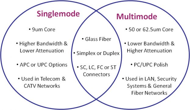
Standard fiber-optic cables have a glass quartz core and cladding. Nowadays, there are two fiber optic cable types widely adopted in the field of data transfer—single mode fiber optic cable and multimode fiber optic cable.
A single-mode optical fiber is a fiber that has a small core, and only allows one mode of light to propagate at a time. So it is generally adapted to high speed, long-distance applications. The core size of single mode fiber has a core diameter between 8 and 10.5 micrometers with and a cladding diameter of 125 micrometers. OS1 and OS2 are standard single-mode optical fiber used with wavelengths 1310 nm and 1550 nm (size 9/125 µm) with a maximum attenuation of 1 dB/km (OS1) and 0.4 dB/km (OS2). SMF is used in long-haul applications with transmission distances of up to 100 km without need a repeater. Typical transmission distances are up 10-40 kilometers. Single mode capable hardware used to be very expensive years ago, but prices for then have came down quicly. Nowadays single mode is very commonly uses.
Multimode optical fiber is a type of optical fiber with a larger core diameter larger (65 or 50 micrometer core) designed to carry multiple light rays, or modes at the same time. It is mostly used for communication over short distances. Multimode Fiber (MMF) uses a core/cladding diameter of typically 50 micrometer/125 mictometer, providing less reach, up to approximately 2 km or less, due to increased dispersion as a result of the larger diameter core.
Depending on your requirements, when going to use fiber, you’re probably first looking for one of these commonly used interfaces: 1000BASE-SX (1 Gbit/s over up to 550 m of OM2 multi-mode fiber), 1000BASE-LX (1 Gbit/s over up to 10 km of single-mode fiber), 10GBASE-SR (10 Gbit/s over up to 400 m of OM4 MMF), 10GBASE-LR (10 Gbit/s over up to 10 km of SMF).
There are many other PHY standards for various data rates and distances, also many common non-standards for even longer distance. The required optical transceivers are usually SFP (1G) or SFP+ modules (10G) plugged into your network hardware. Switches and network adapters with SFP modules allow you to create custom fiber optic high-speed Ethernet networks by plugging in suitable type SFP module. External media converters for devices without SFP slot are also available. A fiber media converter, also known as a fiber to Ethernet converter, allows you to convert typical copper Ethernet cable (e.g., Cat 6a) to fiber and back again.
100G (100 Gb/s) Ethernet has had a good run as the backbone technology behind the cloud, but the industry is moving on. There is expected to be exploding demand for bandwidth in the 5G/mmWave era that’s now upon us. Modern
400G and 800G test platforms validate the cloud’s Ethernet backbone, ensuring support for the massive capacity demands of today and tomorrow. Many service providers and data centers, for various reasons, skipped over 400G Ethernet implementations and are looking toward 800G Ethernet for their next network transport overhaul. Adoption of 400G is still happening, but the growth of 800G will eclipse it before long.
In the future, the speeds of Ethernet networks will increase. Even after the 25, 40, 50 and 100 gigabit versions, more momentum is needed. For example, growing traffic in data centers would require 100G or even faster connections over long distances. Regardless of future speed needs, 200G or 400G speeds are best suited for short-term needs. The large cloud data centers on the Internet have moved to 100GbE, 200GbE and 400G solutions for trunk connections. They also require strong encryption and, in addition, accurate time synchronization of the backbone networks of 5G networks. Media Access Control security (MACsec) provides point-to-point security on Ethernet links. MACsec is defined by IEEE standard 802.1AE. IEEE 802.1X is an IEEE Standard for port-based Network Access Control (PNAC).
High-speed terabit rates do not yet make sense to implement now. The standardization organization OIF (Optical Interworking Forum) has worked up to 800 gigabit connection speeds. The Ethernet Technology Consortium proposed an 800 Gbit/s Ethernet PCS variant based on tightly bundled 400GBASE-R in April 2020. In December 2021, IEEE started the P802.3df Task Force to define variants for 800 and 1600 Gbit/s over twinaxial copper, electrical backplanes, single-mode and multi-mode optical fiber along with new 200 and 400 Gbit/s variants using 100 and 200 Gbit/s lanes. Lightwave magazine expects that 800G Ethernet transceivers become most popular module in mega data centers by 2025. There are already test instruments designed to validate 1.6T designs.
There is also one fiber tpye I have not mentioned yet. Plastic optical fiber (POF) has emerged as a low cost alternative to twisted pair copper cabling and coaxial cables in office, home and automotive networks. POF technology offers an attractive alternative to traditional glass optical fiber as well as copper for industrial, office, home and automotive networks. POF typically utilizes a polymethylmethacrylate (PMMA) core and a fluoropolymer cladding. Glass fiber-optic cable offers lower attenuation than its plastic counterpart, but POF provides a more rugged cable, capable of withstanding a tighter bend radius.
POF has generally been utilized in more niche applications where its advantages outweigh the need for high bandwidth and relatively short maximum distance (only tens of meters). Currently in the market, several manufacturers have developed fiber optic transceivers for 100Mbps Ethernet over plastic optical fiber and there exist also 1Gbit/s versions. Advances in LED technology and Vertical Cavity Surface Emitting Laser (VCSEL) technology are enabling POF to support data rates of 3Gbps and above
POF offers many benefits to the user: it is lightweight, robust, cheap and easy to install; the use of 650nm red LED light makes it completely safe and easier to diagnose as red light can be seen by the human eye. There are several different connectors used for PoF. There is also connector-less option called Optolock, where you can simply slice the plastic fiber with a knife, separate the fibers, insert the fiber into the housing and then lock it in place.
Industrial networks special demands for Ethernet
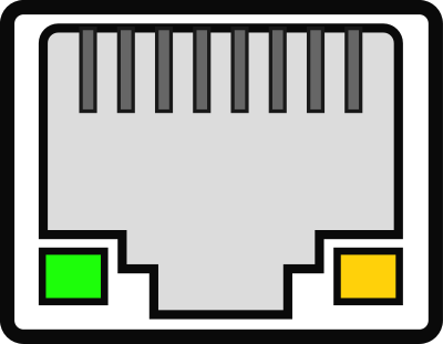
Industrial networks need to be durable. Industrial applications on the field needs often more durable connectors than the traditional RJ-45 connector of office networks.
Here is a list of some commonly used industrial Ethernet connector types:
- 8P8C modular connector: For stationary uses in controlled environments, from homes to datacenters, this is the dominant connector. Its fragile locking tab otherwise limits its suitability and durability. Bandwidths supporting up to Cat 8 cabling are defined for this connector format.
- M12X: This is the M12 connector designated for Ethernet, standardized as IEC 61076-2-109. It is a 12mm metal screw that houses 4 shielded pairs of pins. Nominal bandwidth is 500MHz (Cat 6A). The connector family is used in chemically and mechanically harsh environments such as factory automation and transportation. Its size is similar to the modular connector.
- ix Industrial: This connector is designed to be small yet strong. It has 10 pins and a different locking mechanism than the modular connector. Standardized as IEC 61076-3-124, its nominal bandwidth is 500MHz (Cat 6A).
In addition to those there are applications that use other versions of M12 and smaller M8 connectors.
Current industrial trends like Industrie 4.0 and the Industrial Internet of Things lead to an increase in network traffic in ever-growing converged networks. Many industrial applications need reliable and low latency communications. Many industries require deterministic Ethernet, and Industrial Automation is one of them. The automation industry has continuously sought solutions to achieve fast, deterministic, and robust communication. Currently, several specialized solutions are available for this purpose, such as PROFINET IRT, Sercos III, and Varan. TSN can help standardize real-time Ethernet across the industry.
TSN refers to a set of IEEE 802 standards that make Ethernet deterministic by default. TSN is an upcoming new technology that sits on Layer 2 of the ISO/OSI Model. It adds definitions to guarantee determinism and throughput in Ethernet networks. It will provide standardized mechanisms for the concurrent use of deterministic and non-deterministic communication. AVB/TSN can handle rate-constrained traffic, where each stream has a bandwidth limit defined by minimum inter-frame intervals and maximal frame size, and time-trigger traffic with an exact accurate time to be sent. Low-priority traffic is passed on best-effort base, with no timing and delivery guarantees. Time-sensitive traffic has several priority classes.
Time-Sensitive Networking (TSN) is a set of standards under development by the Time-Sensitive Networking task group of the IEEE 802.1 working group. The majority of projects define extensions to the IEEE 802.1Q – Bridges and Bridged Networks, which describes Virtual LANs and network switches. These extensions in particular address the transmission of very low transmission latency and high availability. Applications include converged networks with real-time Audio/Video Streaming and real-time control streams which are used in automotive or industrial control facilities.
In contrast to standard Ethernet according to IEEE 802.3 and Ethernet bridging according to IEEE 802.1Q, time is very important in TSN networks. For real-time communication with hard, non-negotiable time boundaries for end-to-end transmission latencies, all devices in this network need to have a common time reference and therefore, need to synchronize their clocks among each other. This is not only true for the end devices of a communication stream, such as an industrial controller and a manufacturing robot, but also true for network components, such as Ethernet switches. Only through synchronized clocks, it is possible for all network devices to operate in unison and execute the required operation at exactly the required point in time. Scheduling and traffic shaping allows for the coexistence of different traffic classes with different priorities on the same network.
The following are some of the IEEE standards that make up TSN:
Enhanced synchronization behavior (IEEE 802.1AS)
Suspending (preemption) of long frames (IEEE 802.1-2018)
Enhancements for scheduled traffic (IEEE 802.1Q-2018)
Path control and bandwidth reservation (IEEE 802.1Q-2018)
Seamless redundancy (IEEE 802.1CB)
Stream reservation (IEEE 802.1Q-2018)
Synchronization of clocks across the network is standardized in Time-Sensitive Networking (TSN). Time in TSN networks is usually distributed from one central time source directly through the network itself using the IEEE 1588 Precision Time Protocol, which utilizes Ethernet frames to distribute time synchronization information.
259 Comments
Tomi Engdahl says:
How To Inspect and Clean ST & LC Fiber Optic Tactical Snake Cables
https://www.youtube.com/watch?v=D2JdADjOVZE
Using a Lightel ViewConn 6200 Scope, Chemtronics Electro-Wash and QbE Fiber Optic Cleaning Wipes, Dan at Camplex shows us how to properly inspect and clean tactical fiber optic cables. A straight forward and simple process that ensures a clean and reliable signal every time.
The Lightel VC-6200-PL is a portable hand-held video microscope, ruggedized for field use, for inspecting and cleaning fiberoptic connector endfaces. The dual microscope operation significantly reduces inspection time allowing inspection of both patchcord and bulkhead adapters without changing tips. For single mode and multimode connectors.
Tomi Engdahl says:
Neutrik opticalCON DRAGONFLY Hybrid Camera Connector System
https://www.youtube.com/watch?v=PsmN6QMjhF8
The Neutrik DRAGONFLY fiber optic connector series turned heads throughout the Broadcast & AVL industries as one of the best innovative introductions in fiber optics. Join Camplex & Neutrik’s David Kuklinski for an in-depth discussion about the benefits of the opticalCON DRAGONFLY hybrid camera connector system and learn why people are making the switch!
https://www.neutrik.com/en/product/opticalcon-dragonfly-cable
Ruggedized and dirt protected hybrid connection system
- 2 unique lensed optical connectors
- 2 signal contacts
- 2 power contacts
- 1 ground contact
Tomi Engdahl says:
EXPLORING THE ROLE AND DEVELOPMENT OF CATEGORY CABLES
https://e.lapp.com/us/exploring-the-role-and-development-of-category-cables?em_src=affiliate&em_cmp=PersonifAI4
The evolution of category cables has been driven by industry needs to support the transmission of sensitive data signals over increasing distances and at greater speeds for system operations. From somewhat humble beginnings, category cables were first designed to support telephone and fire alarm applications and have now progressed to extensive use in large data centers and advanced system networks.
Setting the category cabling standards for Industry, standard ANSI TIA/EIA-568 was developed through the joint efforts of the Telecommunications Industry Association (TIA) and Electronic Industries Alliance (EIA) in the United States. In Europe a similar standard ISO/IEC 11801 was created to define cable categories.
While the highest level indicates optimum performance, the majority of today’s application requirements can be satisfied with Category 5e cables. Category 5e offers speeds of up to 1000 Mbps and bandwidth of 100 MHz. However, to prepare for the anticipated system needs of tomorrow, designers and project managers will consider “future proofing” their projects by using higher category level cables which are especially important in applications where precision signals must be transmitted at faster speeds. While Category 8 is at the top of the hierarchy offering speeds of up to 40 Gbps and 2000 MHz bandwidth, there is a 30m length limitation to achieve these attributes. Category 7a at 10,000 Mbps and 1000 MHz at 100 meter maximum lengths follow, but due to its inherent high cost along with Category 8, the debate for potential substitution with fiberoptic cables becomes a valid point of discussion amongst installers, system designers, and others. For most applications being installed today and designed for tomorrow, Category 7 would be the ideal choice because it offers speeds of up to 10,000 Mbps, a bandwidth of 600 MHz, and lengths of up to 100 meters at a competitive cost.
Tomi Engdahl says:
SINGLE PAIR ETHERNET: SIMPLIFYING YOUR ETHERNET CONNECTIVITY FROM SENSOR TO CLOUD
https://e.lapp.com/us/gated-single-pair-ethernet-simplifying-your-ethernet-connectivity-from-sensor-to-cloud?em_src=affiliate&em_cmp=PersonifAI1
With the rise of the Industrial Internet of Things (IIoT), the goal for many manufacturers is to connect all the machines, controls, actuators and sensors in their plant.
Tomi Engdahl says:
Voices of Ethernet | Gordon Bell
Feb. 10, 2023
“We had two or three different networks that were in place within our research group but none that was exactly like Ethernet.” – Gordon Bell
https://www.electronicdesign.com/technologies/communications/video/21259904/ethernet-alliance-voices-of-ethernet-a-conversation-with-gordon-bell?utm_source=EG+ED+Connected+Solutions&utm_medium=email&utm_campaign=CPS230208022&o_eid=7211D2691390C9R&rdx.identpull=omeda|7211D2691390C9R&oly_enc_id=7211D2691390C9R
An important aspect of Ethernet’s beginnings is that it was not simply a clever idea—it also was a necessary one.
After forty years since the birth of Ethernet, Gordon feels so strongly about Ethernet to claim it has become a fundamental component to almost EVERY computer: Processor, Memory/Storage, Internet Port, Operating System, and Application hardware/software.
Gordon Bell had been with Digital Equipment Corporation (DEC) in the early 1960s where his achievements included major contributions to architecting the company’s Programmed Data Processor (PDP) line of minicomputers (though they were explicitly not called “computers” because of that term’s association at the time with prohibitive cost and complexity). He left in 1966 to join the computer-science faculty at Carnegie Mellon University and then, in 1972, returned to DEC as vice president of engineering. In this role, Bell oversaw development of DEC’s historic Virtual Address eXtension (VAX) computers.
Tomi Engdahl says:
Solutions for the Future: Data Center Connectivity
https://www.digikey.com/en/product-highlight/p/phoenix-contact/data-center-connectivity?dclid=CK6ProLnmf0CFU2UGAodj08LVA
Tomi Engdahl says:
Nokia kiihdyttää kohti 800 gigabitin kuituverkkoja
https://etn.fi/index.php/13-news/14601-nokia-kiihdyttaeae-kohti-800-gigabitin-kuituverkkoja
Nokia on esitellyt kuudennen sukupolven optisten kytkinten prosessorinsa. PSE-6s -piirisarjan avulla voidaan toteuttaa 800 gigabitin runkoyhteyksiä yli 2000 kilometrin etäisyyksillä. Prosessorin kapasiteetti yltää 2,4 terabitin siirtämiseen sekunnissa.
2,4 terabittiin PSE-6s -piirisarjoilla päästään, koska alusta tukee piirien välistä suoraa liitäntää. Tämän takia prosessorit voidaan ottaa käyttöön pareittain. Edellispolveen verrattuna ratkaisun siirtokyky kasvaa kolminkertaiseksi.
Tomi Engdahl says:
https://patchbox.com/patchbox-network-cabling-system/?utm_campaign=PP_SKAND_PBXSHOP_2023&utm_source=facebook&utm_medium=paid&hsa_acc=208649056&hsa_cam=6313713680186&hsa_grp=6313713681986&hsa_ad=6313714881986&hsa_src=fb&hsa_net=facebook&hsa_ver=3&fbclid=IwAR0vq2RTawJsVnlRcsOytui6uF4MPMsxQU0V7yocmdU9drvTf4KwGuHA7Ds&ad_id=6313714881986&campaign_id=6313713681986
Tomi Engdahl says:
Voices of Ethernet | Rich Seifert
Feb. 20, 2023
Rich worked on Ethernet and co-write, “The Ethernet, A Local Area Network. Data Link Layer and Physical Layer Specifications.”
https://www.electronicdesign.com/technologies/communications/video/21259908/ethernet-alliance-voices-of-ethernet-rich-seifert?utm_source=EG+ED+Connected+Solutions&utm_medium=email&utm_campaign=CPS230216072&o_eid=7211D2691390C9R&rdx.identpull=omeda|7211D2691390C9R&oly_enc_id=7211D2691390C9R
Along the way, Seifert was responsible for the architecture and design of a wide range of network products, as well as a lengthy list of books and papers that introduced or furthered all sorts of interesting ideas across and beyond the ecosystem—“ether-not,” for example, is Seifert’s term for technologies that fail to deliver Ethernet’s unique and differentiating combination of attributes.
“Ethernet started off as a specific speed, a specific cable, a specific packet format … a lot of specifics … We now have how many zillions of different Ethernet media—10BASE-T, 100BASE-T, Gigabit, fiber, various other cables, wireless and personal area networks and whatever?”
Tomi Engdahl says:
The Evolution of Ethernet
May 4, 2022
Venerable Ethernet provides the backbone of the internet.
https://www.electronicdesign.com/blogs/altembedded/article/21240842/electronic-design-the-evolution-of-ethernet
Tomi Engdahl says:
Voices of Ethernet | David Cunningham
Feb. 17, 2023
In 1987 David joined Hewlett-Packard and was tasked with helping develop a physical layer for a gigabit-speed network using single-mode optical fiber.
https://www.electronicdesign.com/technologies/communications/video/21259909/ethernet-alliance-voices-of-ethernet-david-cunningham
Tomi Engdahl says:
Many years ago Broadcom demonstrated its T4 fast Ethernet operation using the world’s worst cable. The wires were ugly and rusty and had nasty little barbs all over them. Broadcom’s demonstration flawlessly conveyed 100 Mbps of data through the barbed wire. The spacing between barbed strands was set to create an impedance of 100 Ω, the same impedance as in the Category 3 UTP
http://www.sigcon.com/Pubs/edn/SoGoodBarbedWire.htm
Tomi Engdahl says:
https://andry-tino.gitbooks.io/basics-on-industrial-protocols/content/rte/ethernet-enc.html
The EtherType field is present both in IEEE 802.3 and Ethernet II frames, however its meaning is totally different in those 2 frame types.
In IEEE 802.3, the field indicates the length of the payload in bytes.
In Ethernet II, the field indicates which protocol in upper layers is encapsulated in the frame.
This 2-byte field is defined in Ethernet II frames (the most commonly used today) and is utilized to specify which upper-layer protocol is used and will, therefore, be encapsulated into the Ethernet frame.
The standard value for EtherType is 0×0800 which identifies the IP protocol.
https://en.wikipedia.org/wiki/EtherType
Tomi Engdahl says:
https://en.wikipedia.org/wiki/Ethernet_flow_control
Tomi Engdahl says:
Nokia and Globalconnect Achieve 1.2 Tbp/s Over Single Wavelength
https://www.datacenter-forum.com/globalconnect/nokia-and-globalconnect-achieve-12-tbp-s-over-single-wavelength
Nokia today announced it has broken two optical transport records in real-world field trials on GlobalConnect’s live optical network in Europe. The demonstration used Nokia’s sixth generation super-coherent Photonic Service Engine, PSE-6s, to achieve 1.2 Tb/s over metro distances (118km) and 800 Gb/s over long haul distances (2,019 km), both using a single wavelength.
The 1.2 Tb/s speed was using Nokia’s PSE-6s optics deployed over a wavelength division multiplexing (WDM) network using 150 GHz of spectrum on GlobalConnect’s Metro Data Center Interconnect links. Data center interconnection was also demonstrated at 800 Gb/s on a single wavelength over 2,000km, paving the way to single-wavelength 800GE transport across long-haul distances with no regeneration. Reducing the number of coherent interfaces needed enables up to 50% network total cost of ownership savings and up to a 60% reduction in network power consumption.
GlobalConnect operates the largest interconnected fiber network in Northern-Europe, with more than 150,000 km of trenched fiber. Referred to as the ‘gateway to the Nordics’, the backbone connects to local networks and data centers in Denmark, Norway, Sweden, Finland, Nedherland and Germany.
“This trial highlights GlobalConnect’s commitment to offering scalable and flexible high-bandwidth services across our Nordic backbone network. We are pleased to validate Nokia’s latest generation of PSE-6 super coherent optics as an important enabler of these continuous network upgrades, seamlessly operating over our live network with existing coherent channels.”
Nokia will showcase the PSE-6s at the upcoming MWC in Barcelona and the OFC conference in San Diego. The sixth generation PSE can be deployed across Nokia’s 1830 family of optical transport platforms, without the need for new chassis or platforms. PSE-6s can also operate over existing WDM channel plans designed around n x 50GHz channels.
Tomi Engdahl says:
The Semiconductor Industry’s Future Aligns with TSN
Feb. 20, 2023
Semiconductor manufacturing is essential to a range of operations. By utilizing time-sensitive networking, semiconductor manufacturers can future-proof their factory with transparent information for continuous improvement.
https://www.electronicdesign.com/technologies/industrial/article/21260404/cclink-partner-association-the-semiconductor-industrys-future-aligns-with-tsn
What you’ll learn:
What is time-sensitive networking and how does it enable time synchronization and traffic shaping?
How semiconductor producers can modernize their plants with TSN.
How enablement of new functionality offers a competitive advantage in semiconductor manufacturing.
The production of semiconductors is vital to nearly all modern technologies, helping to drive key breakthroughs in the digitalization of industries and in our daily lives. To help manufacturers deliver high-quality products and ultimately grow under these favorable circumstances, vendors of industrial automation devices should offer cutting-edge technologies such as time-sensitive networking (TSN).
TSN is key to helping companies future-proof their operations by maximizing throughput, productivity, precision, and accuracy. It’s the enabling technology for an industry that needs guaranteed data reliability, integrity, and high performance.
The U.S. is the founder and a global leader in semiconductor R&D, chip design, fabless firms, as well as integrated device and microprocessor manufacturing, with American companies having a combined share of almost 50% of total global semiconductor sales.1 These businesses also are among the most automated, with the sector even surpassing automotive as the largest customer of industrial robots, with approximately 109,000 new units purchased globally in 2020 alone.2
Data Transparency is a Must for Continuous Improvement
Fabs and other sector-specific manufacturing facilities have a track record of pushing the performance boundaries of automation and smart manufacturing when it comes to semiconductor production. With every technological step forward, they enhance their competitive advantage.
New systems are taking giant steps forward in functionality and performance. System solutions can independently run entire processes, self-optimize their performance, and adapt to varying conditions in real-time.
Therefore, the first aspect that vendors should deliver with any automation technology destined for the semiconductor industry is maximized performance. This requires access to new levels of process information for both control optimization and process analysis.
Ethernet with TSN Becomes a Game-Changing Market Backbone
TSN is ideal to address these needs. The technology was developed to enhance industrial Ethernet so that it could merge disparate types of data traffic. In effect, thanks to TSN functions, it’s possible to support proprietary automation protocols along with Transmission Control Protocol/Internet Protocol (TCP/IP) communications.
More precisely, by providing guaranteed data transport with bounded low latencies, networks based on TSN are able to transfer best-effort traffic and mission-critical data in a timely manner.
TSN technology delivers these benefits by enabling advanced time synchronization, traffic shaping, and scheduling methods for traffic prioritization, as set out in the IEEE 802.1 Ethernet standards. In particular, the new clock synchronization can support high-speed, extremely accurate and deterministic operations on the shop floor. This is especially important in motion-control applications that are so prevalent in fab applications.
At the same time, traffic prioritization enables the network to feed different systems with either real-time traffic or best effort traffic. New TSN-based Ethernet switches are all that’s needed for the integration and isolation of high-performance traffic in the enterprise.
Given these key benefits, it becomes clear how applying TSN to automation products can drive up the competitiveness of users as well as developers. More precisely, vendors offering TSN-enabled solutions are able to meet current and future market needs while advancing the performance of their devices.
Standard Industrial Protocols with TSN Support Future-Oriented Devices for Fabs
TSN-based Ethernet network technology is crucial to helping vendors deliver truly future-oriented solutions. When vendors opt to use TSN in their products, they can offer TSN functions and enable new levels of performance with their customers.
One example of a TSN-ready protocol is CC-Link IE TSN. It’s the first open industrial Ethernet that combines gigabit bandwidth and TSN. As a result, in addition to traffic synchronization and scheduling, the technology supports today’s Ethernet speeds such as 1-Gb/s transmission rates. This is key to facilitating the prompt, simultaneous transfer of large volumes of IT and OT data from different assets.
CC-Link IE TSN also was designed to provide a broad development ecosystem.
https://www.cc-link.org/
Tomi Engdahl says:
https://www.uusiteknologia.fi/2023/03/13/microchip-tuo-ethernetin-vaativiin-olosuhteisiin/?utm_source=rss&utm_medium=rss&utm_campaign=microchip-tuo-ethernetin-vaativiin-olosuhteisiin
Tomi Engdahl says:
https://www.microchip.com/en-us/solutions/ethernet-technology/single-pair-ethernet/10base-t1s
Established by IEEE®, 10BASE-T1S technology provides a 10 Mbps, multidrop transmission medium that can include up to at least eight transceiver nodes. The transceiver nodes connect to a common mixing segment of up to at least 25m. According to the IEEE specification, these limits are actually “minimum maxima”; this makes it possible to use more than eight nodes and transmit over longer distances.
Established by IEEE®, 10BASE-T1S technology provides a 10 Mbps, multidrop transmission medium that can include up to at least eight transceiver nodes. The transceiver nodes connect to a common mixing segment of up to at least 25m. According to the IEEE specification, these limits are actually “minimum maxima”; this makes it possible to use more than eight nodes and transmit over longer distances.
Tomi Engdahl says:
The Road to Wireless TSN: Its Capabilities and KPIs
March 13, 2023
A wireless time-sensitive-networking ecosystem will be best served by a coordinated approach that allows multiple application protocols to share wired and wireless links through interoperable devices.
https://www.electronicdesign.com/technologies/communications/article/21261895/avnu-alliance-the-road-to-wireless-tsn-its-capabilities-and-kpis
What you’ll learn:
The benefits time-sensitive networking (TSN) can bring to wireless networks.
The similarities among use cases that will pave the way for faster innovation and WTSN market growth.
There’s no question that time-sensitive-networking (TSN) capabilities will come to wireless networks. IEEE and 3GPP already have the standards infrastructure to deliver time-sensitive traffic over both Wi-Fi and 5G networks well underway. The market demand also is certainly evident, coming from a diverse set of use cases.
In industrial use cases, wireless TSN (WTSN) will enable more nimble, efficient production, with reconfigurable factory floors, mobile robots, and automated guided vehicles. In live media, WTSN will replace miles of cable that must be painstakingly redeployed, tested, and troubleshot on a nightly basis at every stop of a tour. In extended reality (XR), WTSN will finally un-tether all of the components of immersive XR systems, giving users true freedom of movement while preventing the latency and jitter issues that can lead to nausea and prevent sustained engagement. Each of these applications needs WTSN to reach its fullest potential.
The question is, therefore, not whether or not implement WTSN, but how. Even without the added challenge of a wireless physical layer, TSN is a varied toolbox with lots of optional features. We don’t anticipate that they will all simultaneously arrive as wireless capabilities. Nor do we think WTSN will necessarily roll out the same way across all industries—factories and live performances have very different networking priorities and market demands.
Tomi Engdahl says:
Single-Pair Ethernet Controllers and Switches Eye Industrial IoT
https://www.electronicdesign.com/resources/products-of-the-week/media-gallery/21261778/electronic-design-products-of-the-week-highvoltage-dualdriver-ic-spe-devices?utm_source=EG+ED+Analog+%26+Power+Source&utm_medium=email&utm_campaign=CPS230309170&o_eid=7211D2691390C9R&rdx.identpull=omeda|7211D2691390C9R&oly_enc_id=7211D2691390C9R&id=21261778&slide=5
A new series of industrial-grade single-pair Ethernet (SPE) from Microchip Technology help reduce cost, wiring, and installation complexity when it comes to building out latency-sensitive smart-factory floors.
The new LAN8650 and LAN8651 are 10BASE-T1S MAC-PHY Ethernet controllers with an SPI bus that makes it easier to connect industrial IoT devices to the cloud. They enable simple MCUs, rather than high-end MCUs with a MAC, to be used when adding sensors, actuators, and other devices to OT and IT networks. These MCUs don’t need their own communication system, and Microchip’s MAC-PHYs connect them into a standard Ethernet system all the way to the cloud over twisted-pair wiring.
If you require higher bandwidth, the company said customers can use MCUs with an integrated Ethernet MAC. Microchip provides an industrial-grade 100BASE-T1 Ethernet PHY transceiver, the LAN8770, that pumps out 100-Mb/s transmit and receive capability over a single unshielded twisted-pair (UTP) cable.
Microchip also is expanding its offerings with industrial-grade versions of its LAN937x and LAN938x Gigabit Ethernet time-sensitive networking (TSN) switches. Equipped with100BASE-T1 PHYs, the switches deliver higher speed as well as enhanced safety, security, and cable reach across Ethernet networks.
Tomi Engdahl says:
A GUIDE TO ETHERNET CABLE CATEGORIES
https://e.lapp.com/us/exploring-the-role-and-development-of-category-cables?em_src=affiliate&em_cmp=PersonifAI4
EVOLUTION OF CATEGORY CABLES
The evolution of category cables has been driven by industry needs to support the transmission of sensitive data signals over increasing distances and at greater speeds for system operations. From somewhat humble beginnings, category cables were first designed to support telephone and fire alarm applications and have now progressed to extensive use in large data centers and advanced system networks.
Setting the category cabling standards for Industry, standard ANSI TIA/EIA-568 was developed through the joint efforts of the Telecommunications Industry Association (TIA) and Electronic Industries Alliance (EIA) in the United States. In Europe a similar standard ISO/IEC 11801 was created to define cable categories. In addition to detailing complete system operating functionalities, these standards define the hierarchy for category type cables and the various electrical parameter requirements, and specify cable pin and pair assignments. With the development of emerging new technologies there is an abundance of related industry standards driven by specific global regions which have proliferated from TIA/EIA and ISO/IEC documents.
Tomi Engdahl says:
Simplify Automotive Networks for Real-Time Driver Assistance
March 8, 2023
Sponsored by Texas Instruments: FPD-Link SerDes technology is equipped to readily handle the massive amounts of data transferred in ADAS systems.
https://www.electronicdesign.com/tools/learning-resources/whitepaper/21260142/texas-instruments-simplify-automotive-networks-for-realtime-driver-assistance?pk=DesEssen-03162023&utm_source=EG+ED++Sponsor+Paid+Promos&utm_medium=email&utm_campaign=CPS230314034&o_eid=7211D2691390C9R&rdx.identpull=omeda|7211D2691390C9R&oly_enc_id=7211D2691390C9R
In the automotive industry, technologies that influenceadvanced driver-assistance systems (ADAS) are evolving rapidly. Applications range from basic vehicle functions such as lighting, braking, and cruise control to more complex uses like engine and transmission control, traffic warnings, proximity to other cars, and correct lane use.
Because highly automated and connected cars will rely on more than one type of network architecture, designers are being challenged to employ multiple network technologies simultaneously. The goal is to communicate critical information in real-time and with precision to keep drivers informed about operational data and the status of the vehicle.
Communication Protocols in
Modern ADAS Architectures
https://www.ti.com/lit/wp/slyy219/slyy219.pdf?HQS=null-null-adas-adascomm-asset-whip-electronicdesign_03-wwe_awr&DCM=yes&dclid=CIjS1anP4v0CFQKMmgodlpQPJA
The modern vehicle relies on high-speed automotive
communication technologies that move data faster and
farther to accelerate vehicle safety and autonomy.
Ethernet
Ethernet is one of the most common high-speed
interfaces found in homes and offices, and is becoming a
predominant communication protocol for vehicles. Some
vehicles use Ethernet to transport a variety of high-speed
data; automotive applications such as radar and lidar
modules use single-pair Ethernet technology. Single-pair
Ethernet uses the Ethernet standard, but data transmits
over a single, twisted pair of wires, enabling reduced
cable weight and cost within the vehicle.
Ethernet is a packetized system, where packets
between nodes on various parts of the network
transfer information. Also like a CAN bus, Ethernet is
bidirectional, and the speed possible on any individual
link decreases as the number of nodes on the system
increases. For single-pair Ethernet, the speed on any
individual link is limited to one specific speed (10 Mbps,
100 Mbps, 1 Gbps) and no dynamic speed changes
on the link may occur. Still, single-pair Ethernet can
transport data over a link up to 1,000 times faster than
a CAN bus. Changing to single-pair Ethernet would
optimize the data transmission speed over a CAN bus,
but since Ethernet’s cost per node is higher, it probably
will not replace – but rather will augment – a CAN bus.
Some cars today use single-pair Ethernet for data-
intensive requirements such as backup cameras
and radar. For example, the DP83TC812S-Q1 and
DP83TG720S-Q1 from Texas Instruments (TI) are single-
pair Ethernet physical layers (PHYs), screened to
Automotive Electronics Council-Q100 grades 1 and
2, and include a loopback test mode for facilitating
system diagnostics compliant to Institute of Electrical
and Electronics Engineers (IEEE) 802.3bw and 802.3bp
automotive standards. To transport video over an
Ethernet network, even if there is only one video channel
being transported, the video must be compressed at
its source and then decompressed at the destination
to avoid exceeding Ethernet bandwidth limitations unlike
FPD-Link™ technology, which allows for uncompressed
transport of video data. For an application such as
a backup camera, there needs to be a relatively high-
power processor in the camera to compress the image
sufficiently to get it into the Ethernet network.
The need for a high-power processor in turn means
that the camera will be physically larger and more
expensive. The camera will have a higher power
dissipation than an approach that does not require
much image processing. Another disadvantage of this
solution is that video compression and decompression
add latency to the link. If several cameras or other
video sources are sharing the same Ethernet network,
there is a trade-off between the amount of compression
(and corresponding video quality) and the number of
supported video channels. It is possible to mitigate this
limitation by setting up multiple networks within the car in
a hierarchical configuration. There might be one network
that deals only with engine control and diagnostics, a
second network that handles backseat entertainment
and the audio system, and another network that handles
driver assistance functions such as vision enhancement
cameras. In the end, single-pair Ethernet provides higher
capacity than the CAN bus for transmitting data like
radar and lidar, at the expense of greater complexity,
but still struggles to handle the highest-bandwidth
applications such as video.
FPD-Link technology
FPD-Link is a proprietary automotive SerDes technology
developed for real-time, uncompressed transmission
of high-bandwidth data. Specifically, FPD-Link was
developed to transport video data within the car,
Tomi Engdahl says:
https://etn.fi/index.php/13-news/14724-maailmanennaetys-optisen-linkin-symbolinopeudessa
Tomi Engdahl says:
New Data,
New Insights
10BASE-T1L Connected
Edge Sensors Improve
Outcomes
https://www.digikey.com/en/pdf/a/analog-devices/10baset1l-connected-edge-sensors-improve-outcomes
Connector, Gland, and Grip Options for Industrial-Automation Cabling
https://www.digikey.com/en/articles/connector-gland-and-grip-options-for-industrial-automation-cabling?dclid=CJTq9M-V6v0CFecMogMdF_MB6w
Tomi Engdahl says:
MicroMod Single-Pair Ethernet Function Board
Sparkfun’s ultra-low-power Ethernet function board results from their collaboration with Analog Devices, Harting, and Würth Elektronik
https://www.digikey.fi/fi/product-highlight/s/sparkfun/micromod-function-board
SparkFun’s COM-19038 MicroMod single-pair Ethernet function board introduces the ADIN1110 10BASE-T1L two-wire Ethernet protocol into the SparkFun MicroMod ecosystem. Using the ADIN1110 Ethernet transceiver from Analog Devices Inc., this function board provides a development tool for long-range, 10 Mb/s single-pair 10BASE-T1L Ethernet applications.
The SparkFun MicroMod single-pair Ethernet function board features a Harting T1 industrial single-pair Ethernet connector and passive components from Würth Elektronik, all populated on a MicroMod function board that can easily be added to the MicroMod system via its M.2 connector, which is plug-and-play, no soldering required.
The ADIN1110 is an ultra-low-power, single-port, two-wire Ethernet transceiver. It features an integrated media access control (MAC) interface to allow direct connections with a host controller via a serial peripheral interface (SPI) at 10 Mbp/s full-duplex. The specified cable reach for edge nodes is up to 1,700 meters.
https://www.digikey.fi/fi/products/detail/sparkfun-electronics/COM-19038/16511103
Tomi Engdahl says:
Cade Metz / New York Times:
The Association for Computing Machinery awards Bob Metcalfe the Turing Award for his work on Ethernet at the Palo Alto Research Center in the 1970s — In the 1970s, Bob Metcalfe helped develop the primary technology that lets you send email or connect with a printer over an office network.
https://www.nytimes.com/2023/03/22/technology/turing-award-bob-metcalfe-ethernet.html
Tomi Engdahl says:
What Does a Bad Termination Look Like?
https://www.truecable.com/blogs/cable-academy/what-does-a-bad-termination-look-like#page_comments=1
Written by Don Schultz, Technical Sales Representative and Fluke Networks Certified Technician
Got ya! You came into this article thinking we were going to talk about unfair firings. Nope. In this article, we are talking about thoroughly jacked-up RJ45 and keystone jack terminations. The content that follows may be shocking. Most people will find it quite humorous. Viewer discretion is not advised. You have to see this!
Tomi Engdahl says:
How do you test for noise on a CAT5 cable run?
https://superuser.com/questions/315536/how-do-you-test-for-noise-on-a-cat5-cable-run
Tomi Engdahl says:
Can ethernet cables cause ground loops?
https://www.audiosciencereview.com/forum/index.php?threads/can-ethernet-cables-cause-ground-loops.30946/
Right… Ethernet is transformer-isolated so there is no ground. The exception could be PoE (Power over Ethernet) which is rare.
I have seen some admittedly rather poor examples where the shield is connected to the main circuit ground. Nothing like that from a reputable manufacturer though.
The other exception is Cat 6A cabling/devices which do have a grounded sheath. If you try to use these in your home audio setup, though, the audio device will not have the ground connected on the jack so it still shouldn’t matter.
If you live where standard network cable is UTP (like in the US), the potential for ground loops is fairly low. That being said, any networked device that is IEC Class I tends to connect FGND to chassis ground, which in turn is connected to PE. If you do have shielded cable as is common over here in ol’ Europe, this results in substantial potential for ground loops.
Cat 6a is shielded and is rated for longer cable runs. For in-wall wiring, cat5/cat6 have a maximum distance of 100 meters which really ought to be enough for anybody. But if houses require longer runs, yeah, there might be cat6 around. I don’t know what happens if you have cat6a in the wall and use a cat6 patch cable. If you are going to connect audio equipment to ethernet that’s wired cat6a and you think that’s causing a ground loop issue, get an ethernet switch (not a hub) that supports the desired long-distance network speed. Use the appropriate cabling between the switch and the in wall-port. Use a non-shielded cable (short length) between the switch and audio device. Make sure its a switch and not a hub. The terminology is somewhat backward compared to how it’s used in audio. A “switch” reads each packet and then only repeats the packet on the appropriate ports. Hence your unshielded length to the switch will be fine and the switch will repeat the packet to the rest of the network over grounded connection for longer cable run. Where most switches used to be all plastic you do now see metal near the jacks and I believe this is for shielded cable although I don’t pay much attention anymore as I have WiFi in my house.
You can get any cat cable shielded or not. Ive installed cat cables in hundreds of locations and only used shielded ones once. The cable is already very noise immune due to the twisted balanced pairs. The only ground connection in a cat cable is the shield if there is one (except for POE). For the shields to carry thru you need shielded jacks and connectors, special switches and patchbays. Very unlikely your home system has these special devices, so very unlikely you will get a ground loop.
You are correct that I did not word my answer well. You can use shielded ethernet cables in pretty much any application. But, as you’ve said, if you aren’t using the proper equipment, it’s the equivalent of wrapping them in aluminum foil yourself. In order for the shielding to be grounded, though, you need equipment which is grounded and has the appropriate connectors.
And almost all Ethernet cables don’t have shields.
If the RJ45s aren’t shielded theres no ground connection.
Allow me to summarise the situation as I see it:
Unshielded cables (UTP) are by far the most common everywhere in the world.
Switches and computers almost always have shielded Ethernet jacks.
Broadband routers vary; I have examples of both.
Patch panels typically have unshielded jacks, but few people have those at home either way.
If ground loops are a concern:
Use an unshielded cable to connect the affected equipment.
An unshielded cable can connect directly to a shielded patch panel; there is no need for an intermediate switch.
To answer the question in the title, yes, Ethernet cables can cause ground loops if they are shielded. Unshielded cables can’t cause ground loops since they have no ground wire. PoE complicates matters a little, but it’s rarely used with audio equipment anyway.
Because of the balanced and transformer isolated nature of Ethernet, the high frequency content and the twisted pair construction. the shield dose not need to be connected to ground to be effective.
May (most) devices don’t connect the shield to ground.
Cat >6 usually do
Shielding is typically maintained from one cable end to the other using a drain wire that runs through the cable alongside the twisted pairs. The shield’s electrical connection to the chassis on each end is made through the jacks. The requirement for ground connections at both cable ends creates the possibility of creating a ground loop. This undesirable situation may compel currents to flow in the network cable shield and these currents may in turn induce detrimental noise in the signal being carried by the cable.
If you have to devices with ground connected to shield and a shielded cable. you can have ground loops.
in this cases use a unshielded cable.
BTW Cat rating and cable type don’t directly correlate.
Tomi Engdahl says:
Application Report
SNLA107A – June 2008 – Revised April 2013
AN-1862 Reducing Radiated Emissions in Ethernet 10/100
LAN Applications
https://www.ti.com/lit/ml/snla107a/snla107a.pdf?ts=1679917986088&ref_url=https%253A%252F%252Fwww.google.com%252F
Tomi Engdahl says:
Silence Noise on Your Network
Jan. 1, 2005
The identification and elimination of noise has always been a major concern in the installation, testing, and certification of LAN networks, as well as a key part of ongoing network maintenance and troubleshooting. Contract cable installers and internal network maintenance staff must understand the various sources of noise that can interfere with legitimate signals and degrade data transmission over
https://www.ecmweb.com/content/article/20893861/silence-noise-on-your-network
Tomi Engdahl says:
Why am I getting noise with my network cable connectors?
https://diy.stackexchange.com/questions/109794/why-am-i-getting-noise-with-my-network-cable-connectors
Tomi Engdahl says:
https://electronics.stackexchange.com/questions/176218/what-should-be-the-size-package-of-bob-smith-termination-resistor
https://e2e.ti.com/support/interface-group/interface/f/interface-forum/302618/dp83848c-transmit-termination-resistor-rating
Tomi Engdahl says:
Bob Smith Termination: Is it Correct for Ethernet?
https://resources.altium.com/p/bob-smith-termination-it-correct-ethernet
What is Bob Smith Termination?
Originally patented by Bob Smith, this refers to a certain set of resistors that provides termination for the center tap of a common-mode choke that is used in Ethernet routing. When routing between an Ethernet PHY and discrete magnetics circuitry, this termination scheme is used to ground the center taps of the transformers used in the magnetics circuits. Note that this is used in Ethernet routing to provide a sink for common-mode noise that may transfer from the PHY side to the connector side.
Bob Smith termination uses four 75 Ohm resistors (2 for Rx, 2 for Tx) and a capacitor to provide an impedance-matched path back to a ground point in the system. Depending on which application note you read, you’ll find that the ground point ranges from chassis ground to analog ground, although this is a different signal integrity issue that relates to grounding and planning mixed-signal return paths.
If we look at the above circuit, the need to terminate the center tap to ground seems to make sense for common-mode noise reduction. By diverting some common-mode emissions to ground, you’ve effectively increased the system’s overall common-mode rejection ratio (CMRR). This means the return loss back to ground should be as low as possible. This is where the objections to Bob Smith termination come into play.
Objections to Bob Smith Termination
52.3 Ohms vs. 75 Ohms
I’ve never met Jim Satterwhite, nor had I ever heard his name before looking into the achievements of Bob Smith. Jim is probably the most cited author to claim that the Bob Smith termination scheme is not optimal, and that a different termination scheme should be used. You can read his article on the topic here. His solution is simple: use 52.3 Ohm resistors instead of 75 Ohm resistors.
Very simply, Satterwhite’s objection is that Bob Smith’s termination scheme would only be optimal if the differential impedance of a typical UTP cable was 145 Ohms. Obviously this is much higher than the differential impedance of 100 Ohms used in Ethernet cables. Satterwhite measured the impedance of a single differential pair in a UTP cable versus other configurations and retrieved the specified characteristic and differential impedances, although I don’t think he realized what he was measuring.
Satterwhite then compared return loss values for his scheme and the original Bob Smith termination scheme, and he found that his proposed scheme provides ~10 dB less return loss for common-mode currents entering the system ground. This is clearly an improvement; less common-mode noise is reflected and we’d expect less common-mode EMI from this section of the system and from a UTP cable itself. What happens next depends on keeping the return path for this noise away from ferrites above the system ground, which has raised its own set of objections from the SI community.
Bohnert’s Study
If you read through online PCB design forums, you’ll see other designers quoting a study by Royce Bohnert. He showed that the Bob Smith termination scheme (75 Ohm resistors), Jim Satterwhite’s modified scheme (52.3 Ohm resistors), and no termination at all did not appear to produce any difference in return loss measurements.
Who’s Correct?
Despite the objections, I don’t see a reason to not use a termination network with this topology, regardless of whether it uses 52.3 Ohms or 75 Ohms. When in doubt, it doesn’t hurt to run a simple simulation with your choke and proposed termination method. You may find that Satterwhite’s assertions are correct and you’re better off using 52.3 Ohms instead of 75 Ohms in your termination network. With the right design tools, you can run SPICE simulations with specific component models directly from your schematic and determine which termination network is right for you. Don’t forget to include the capacitor in your simulations!
Bob Smith Termination vs Proper Termination
http://www.teli.us/EN_BSTermination04.pdf
“the Bob Smith termination” method is applied
worldwide with great acclaim. For CAT 5 and CAT 5E cable an improvement in
return loss achieved by replacing the 75 ohm resistors by 52.3 ohm resistors,
would be from 15 dB to more than 28 dB, given a variation in common mode
impedance of +/- 5 ohms. The variation of common mode characteristic
impedance is taken into account in the calculation of return loss.
Tomi Engdahl says:
ENT-AN0098
Application Note
Magnetics Guide
https://ww1.microchip.com/downloads/en/Appnotes/VPPD-01740.pdf
Tomi Engdahl says:
Kontron lisäsi nopean ethernetin postimerkin kokoiseen moduuliin
https://etn.fi/index.php?option=com_content&view=article&id=14758&via=n&datum=2023-03-24_16:47:19&mottagare=30929
Sulautettujen laitteiden moottorien kehitys on välillä hämmästyttävän nopeaa. Hyvä esimerkiksi kehityksestä on saksalaisen Kontronin uusi moduuli. Mitoiltaan vain 30 x 30 millimetrin sirulle on saatu istutettua kaksi gigabitin ethernet-liitäntää, viiden ytimen Arm-prosessori ja tuki verkon reaaliaikaisten toimintojen ohjaamiseen.
Mallimerkinnältään OSM-S i.MX8M Plus on itse asiassa markkinoiden ensimmäinen kompakti järjestelmämoduuli, jossa on tuki kahdelle GbE-liitännälle ja TSN-toiminnoille. Suoritinosa perustuu neljään Arm Cortex-A53- ja yhteen Cortex-M7-ytimeen. Niiden rinnalla on 2,3 TOPSin suorituskyvyn omaava neuroverkkoprosessori.
Tomi Engdahl says:
Best ethernet cables 2023
And how to decide which is right for you
https://www.techadvisor.com/article/724186/best-ethernet-cables.html
Wi-Fi is amazingly handy because it gives you a network connection without wires. But if you’re looking for the best speed, performance and reliability then wired is the way to go – if your device has an Ethernet port, that is.
Regardless of whether you call them Ethernet cables or network cables, it isn’t as simple as grabbing the first one you see and hoping for the best. Not all Ethernet wires are created equal, and to make sure you’re getting the best speed, you need to make sure you buy the right ones. That’s where we come in.
In this article, we’ll run through seven of the best ethernet cables you can buy right now. But it’s also worth reading the FAQ section at the bottom of the page to figure out what’s actually best for you.
Tomi Engdahl says:
Why is Bob Smith termination for Ethernet recommended if it’s wrong?
https://electronics.stackexchange.com/questions/161436/why-is-bob-smith-termination-for-ethernet-recommended-if-its-wrong
Tomi Engdahl says:
https://blog.semtech.com/ethernet-protection-methodology
Tomi Engdahl says:
Industrial MPU Enables Fast and Accurate Real-Time Control with EtherCAT
https://www.mwrf.com/resources/products-of-the-week/media-gallery/21262624/microwaves-rf-products-of-the-week-march-27-2023?utm_source=RF+MWRF+Today&utm_medium=email&utm_campaign=CPS230324091&o_eid=7211D2691390C9R&rdx.identpull=omeda|7211D2691390C9R&oly_enc_id=7211D2691390C9R&id=21262624&slide=5
Renesas Electronics’ RZ/T2L industrial microprocessor supports the EtherCAT communication protocol for high-speed, accurate real-time control for industrial systems. The RZ/T2L MPU leverages the hardware architecture of the RZ/T2M, while reducing the chip size by up to 50%. The RZ/T2L has an Arm Cortex-R52 CPU with a maximum frequency of 800 MHz and an EtherCAT slave controller from Beckhoff Automation for Ethernet communication.
Tomi Engdahl says:
Building A 10BASE5 “Thick Ethernet” Network
https://www.mattmillman.com/projects/10base5/
I can hardly claim to have worked professionally with 10BASE5 as when I first started building my own 10BASE2 networks in 1997, 10BASE5 was long obsolete. Back then, I knew about 10BASE5, but it wasn’t practical, affordable or interesting enough for me to attempt building one.
Fast forward to 2012, and 10BASE5 is now truly a vintage technology. Anyone studying something I.T. related likely will at some point have been told about this stuff, because it’s very important in the history of computing.
Tomi Engdahl says:
Ethernet cables: Everything you need to know
By Brian Nadel last updated May 13, 2020
A guide to Ethernet cables, from Cat 1 to Cat 8
https://www.tomsguide.com/reference/ethernet-cables-explained
Tomi Engdahl says:
Industrial-Grade MPU Plugs EtherCAT into Factory Floor
The latest industrial-grade microprocessor (MPU) from Renesas Electronics supports the EtherCAT communication protocol to bring accurate real-time control to servo drives, inverters, industrial robots, or other factory machinery.
Renesas said the RZ/T2L features the same architecture as its flagship industrial-grade MPU, the RZ/T2M, even though it’s 50% smaller than the high-end MPU. Ideal for factory automation and other areas such as medical equipment and building automation, where EtherCAT is playing a part, the RZ/T2L is based on Arm’s Cortex-R52 CPU clocked at 800 MHz. The EtherCAT controller was designed by Beckhoff Automation.
The RAM inside the MPU is equipped with error-correction code (ECC). A large amount of memory directly connected to the CPU reduces unpredictability in execution time that can be caused by memory cache, boosting reliability.
https://www.electronicdesign.com/resources/products-of-the-week/media-gallery/21263504/electronic-design-products-of-the-week-digital-dc-current-sensors-highdensity-connectors?utm_source=EG+ED+Analog+%26+Power+Source&utm_medium=email&utm_campaign=CPS230406052&o_eid=7211D2691390C9R&rdx.identpull=omeda|7211D2691390C9R&oly_enc_id=7211D2691390C9R&id=21263504&slide=5
RZ/T2L
infoActive
High-Performance MPU Realizing High-Speed and High-Precision Real-Time Control with EtherCAT
https://www.renesas.com/sg/en/products/microcontrollers-microprocessors/rz-mpus/rzt2l-high-performance-mpu-realizing-high-speed-and-high-precision-real-time-control-ethercat
Tomi Engdahl says:
Air-Gapped Networks (Part 1): Air-Gapped Madness
April 11, 2023
It’s not enough to have an air-gapped network—that network must be located in a secure facility, too.
https://www.electronicdesign.com/technologies/embedded/article/21263671/digistor-airgapped-networks-part-1-airgapped-madness?utm_source=EG+ED+Connected+Solutions&utm_medium=email&utm_campaign=CPS230406075&o_eid=7211D2691390C9R&rdx.identpull=omeda|7211D2691390C9R&oly_enc_id=7211D2691390C9R
What you’ll learn:
The various government classifications for sensitive information.
Secure, air-gapped facilities known as “SCIFs” and “SAPFs” are used to limit access to some types of classified information.
The roles of people involved in maintaining access to SCIFs and SAPFs.
Tomi Engdahl says:
https://hackaday.com/2022/11/03/say-no-to-obsolescence-wire-up-your-house-with-fiber/
Tomi Engdahl says:
Identify hardware with OUI lookup in Wireshark
https://www.comparitech.com/net-admin/oui-lookup-wireshark/
Sometimes it’s useful to know the manufacturer of a given network adapter. Wireshark makes that information easy to find by performing an automatic OUI lookup on every captured frame.
An Organizational Unique Identifier (OUI) is a code embedded in the first three bytes of a MAC address. It identifies the device’s vendor. For instance, if the first three bytes of your network adapter are 3C:FD:FE, your card was sold by Intel.
To give an example, the MAC address of my laptop is 54:27:1E:44:EC:BA. That means the OUI is 54:27:1E and the final three bytes are a unique identifier.
One caveat to keep in mind is that the OUI denotes the vendor and not the chipset manufacturer.
Wireshark automates OUI lookup, which makes it very easy to identify the vendor of any given network adapter. You need to know the IP address or hostname of the target machine. Wireshark does the rest.
One of the easiest ways to perform an OUI lookup on a given host is to ping it.
Wireshark handles OUI lookup in IPv6 is the same way as IPv4. That’s because the OUI code is embedded in the frame header, not the packet itself.
Tomi Engdahl says:
https://www.cablesandkits.com/learning-center/what-are-cat8-ethernet-cables
Tomi Engdahl says:
https://www.cdw.com/content/cdw/en/articles/hardware/cat5-vs-cat6-ethernet-cables.html
Tomi Engdahl says:
https://www.cables-solutions.com/basics-1000base-sx-1000base-lx-sfp.html
https://www.verkkokauppa.com/fi/product/289268/TP-LINK-MC200CM-mediamuunnin
https://www.verkkokauppa.com/fi/product/289271/TP-LINK-MC210CS-mediamuunnin
Tomi Engdahl says:
TP-Link MC220L gigabitin SFP mediamuunnin
https://www.verkkokauppa.com/fi/product/225469/TP-Link-MC220L-gigabitin-SFP-mediamuunnin