Four channel dimmer rack
Copyright Tomi Engdahl 1998,1999,2000
Technical specifications
- Power input: 230V AC 50 Hz 10A max.
- Number of output channels: 4
- Output power: 900W maximum per channel, 2300W maximum total
- Fusing: 4A fuse per channel, 10A breaker on mains input
- Controlling: standard 0-10V input
- Case: Plastic case
WARNING: Under no circumstances should any reader construct any mains operated equipment unless absolutely sure of his/her abilities in this area. The author takes no responsibility for any injury or death resulting from, whether directly or indirectly, the reader's inability to appreciate the hazards of household mains voltages. I have tried to get the circuit diagrams correct as I can, but there is no guarantee that they are completely free from errors. There is no guarantee that this design is or meets the regulations. (My prototype has worked well, but that does not guarantee anything on the circuit you construct.)
Introduction to dimming
Remotely controlled light dimmers in theatrical and architechtural applications use 0-10V control signal for controlling the lamp brightness. In this case 0V means that the lamp is on and 10V signal means that the lamp in fully on. A voltage between those values adjust the average voltage which is applied to the ligh bulb. This average voltage controlling is made by controllign the position in which phese the output triac fires (sooner it fires more power is applied to lamp).
The the phase when the TRIAC will fire is controlled by the input voltage which is compared to an internal ramp signal generated by the dimmer. In this arrangement the input voltage linearly controls the time delay between mains zero crossing and the triac triggering.
Circuit diagram
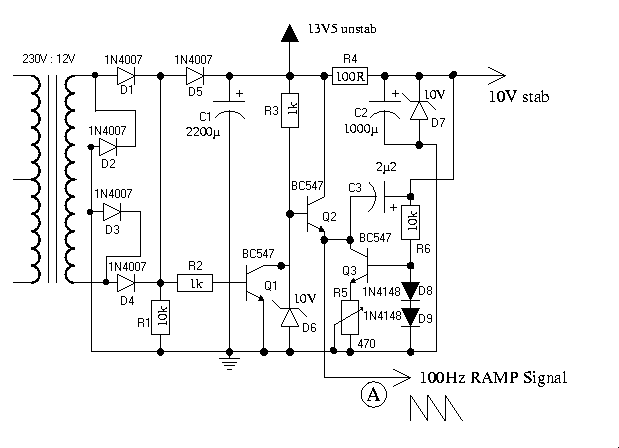
Ramp generator
This circuit is a real core of the dimmer system. This circuit generates ramp 100 Hz signal which is syncronized to the incoming mains voltage. The ramp signal which is generated will start form 10V and go linearly down to 0V in 10 milliseconds. At the next mains voltage zero crossing the ramp signal will again immediatly start from 10V and go down to 0V. This same ramp signal is fed to all of the 4 comparators in the dimmer.
The following ramp signal generator is quite simple ramp generator based on discrete transistors which do some switching, capacitor and a constant current source made by using one transistor. The idea of the circuit is taken from N-channel light dimmer design made by Kari Hautio.
Trimmer R5 is used in controlling the ramp signal. If you have an oscilloscope, then it is best to use it to look at the situation so that the signal send by the circuit is what is described eariler. A good approximation is so start at position that R5 is set to it's center position.
Besides generating the ramp signal the sampl generator circuit works as a power supply comaprator part of the dimmer. The 13.5V unstabilized output is used to power the comparator section (that putput can be loaded up to 100 mA). The 10V stabilized voltage is used only for internal use in ramp generator (that stabilized 10V voltage can be also used for some extra low power circuitry which need 10V voltage, for example local dimmer controls if such thign are needed).
The ramp generator used a normal mains transformer which can output at least 200 mA of current, because it powers both ramp generator itself and the voltage comparator circuits. I relected a tranformer which has an invernal overload protection inside the transformer (overhating protection fuse), so I did not need to add any extra fuses for this transformer. If you use other kind of transformer, select a suitable fuse to protect it. In any case a 200 mA fuse on the secondary would be a good idea, propably also a primary fuse.
Component list for ramp generator:
R1     10 kohm 0.25W
R2     1 kohm 0.25W
R3     1 kohm 0.25W
R4     100 ohm 1W
R5     470 ohm trimmer
R6     10 kohm 0.25W
C1     2200 uF 25V electrolytic
C2     1000 uF 25V electrolytic
C3     2.2 uF 25V
D1-D5  1N4007
D6-D7  10V zener diode 1W
D8-D9  1N4148
Q1-Q3  BC547
TRANS  Transformer 230V primary and 12V 200 mA secondary
Voltage comparators
                            | \      470 ohms   1N4148
 0-10V input >-+------------|+  \
               |            |    >-----/\/\/\----|>|--+
              47kohm    +---|-  /                     |
               |        |   | /                   TRIAC card
               |        |                         control input
               |   100 Hz ramp signal                 |
               |   from ramp generator                |
               |                                      |
Input ground --+--------------------------------------+- Logic ground
                                                        (ramp generator ground)
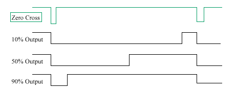
The circuit works so that the comparator output in low when the input voltage is higher than the ramp voltage.
When the ramp signal
voltage gets lower than the input voltage the comparator output goes high which causes that current starts to flow through resistor to
optocoupler which causes the triac to cnoduct.
Because the ramp signal starts at every zero crossing from 10V and goes linearly to 0V at the time of one half cycle the input voltage controls the time when the triac is triggered after every zero crossing. This effectively means that the control voltage controls the ignition phase of the triac. The output of the comparator is a pulse width modulated signal is is syncronized to mains voltage. The start of every PWM pulse changes the position depending on control voltage and the end is at zero crossing of mains votlage. The start of the pulse is used to trugger the output triac.
Because the dimmer has 4 channels, you need four of such units. A classical LM324 operational amplifier is very suitable to be used in this project, because it has four suitable operational amplifiers in one case. This part of the circuitry is powered from unregulated 13.5V voltage supplied by the ramp card. One ramp generator generates the operating voltage and the ramp signal for all four comparator channels.
The picture below shows the output signals the voltage comparator outputs to the triac card at different dimmer settings:
Component list for 4 channel comparator card:
4x     47 kohm 0.25W resistor
4x     470 ohm 0.25W resistor
4x     1N4148 diode
1x     LM324 quad opamp
Triac output card
I used Velleman K2634 four channel triac card for the output card. The reason for using this card is that by using a good quality electronics kit I can get easily and quite cheaply a safe and easy to build mains voltage interface. Check the Velleman K2634 documentation for mode details on the kit.
I added small extra heatsinks to the triacs on the card to make them be able to handle 4 amperes per output without overheating.
     R1                                      9V psu +
     820                                       |
+---/\/\/\----------+   +----------------------+------------------------> 230V
+Vin               1|   |5                     |                         Hot bus
                   +=====+ IC1           +-+   | MT1
In                 |     | Optoisolator  | G\  |
10-15V             |4N27 | Driver        |   -----    TRIAC
(10 mA current     +=====+               |   /\ \/    Q600 4F31
      LED          2|   |4               |   -----
+-----|<|-----------+   |                |     | MT2
Ground                  \ R2             /     |
                        / 12K            \     |                        hot
                        \                / R4  +-------FUSE-------+---> to load
                        /                \220R          4A        |
                        |                |                        |
                        |               |/  T1                    |
                        +---------------|   BC547                 |
                        |               |V                       ---  C1
                        \                 \                      ---  47 nF 250V
                        /  R3             |                       |   (X2 rating)
                        \  10K            |                       \
                        /                 |                       /  R5
                        |                 |                       \  100 ohm
                        +-----------------+---- 9V psu -          /  3W
                                                                  |
                                                                  |    neutral
                                                                +-+--> to load
                                                                |
                                                                |
                                                                +----> 230V
                                                                       Neutral bus
The triac card contains four controlling circuits similar to circuit shown above fitted into one circuit board (provided by Velleman). Each output channel triac needs it's separate small heatsink to be able to handle full 4A current (around 1A maximum withouth heatsink). Those heatsinks are not allowed to touch each other unless they are isolated from the triac case (in my prototype they were not).
Each output is protected with 4A fuse, which should be fast type to give at least some kind of protection to the triac against overload. Pleace note that even a fast fuse does not make this output short-circuit proof, so if you happen to short the output, you quite propably loose both triac and the fuse (in some fortunate cases you might only burn the fuse).
This part of circuitry needs it's own power supply of 9V for generating the triac trigger pulses. This power supply must be separate from any other power supply in the quipment, because one end of the this 9V voltage is directly connected to mains input. Each triac controlling circuitry needs around 50 mA, so you need around 200 mA total.
The LED shown in the circuit diagram was wired so that it is visible on the dimmer front channel. It is very useful to monitor the state of the dimmer channels.
The components R5 and C1 make an output filter for the circuit to handle highly inductive loads better than without it. The circuit can be built without them, but this might cause some problems with some inductive loads.
Component list for single output channel (4 total needed for complete dimmer):
R1     820 ohm 0.25W
R2     12 kohm 0.25W
R3     10 kohm 0.25W
R4     220 ohm 0.5W
R5     100 ohm 3 W
C1     47 nF 250V (with X2 rating approved for mains filtering)
T1     BC547
IC1    4N27 optocoupler
LED    Red LED
TRIAC  Q600 4F31
FUSE   4A fast acting fuse
9V power supply for triac card
                  230V:8V@200mA

 LIVE ------FUSE---+  +-----+  +------+-------- +
            32mA   )||(     |  |+     |
230VAC             )||(    BRIDGE    === 4700uF  9V DC
                   )||(   RECTIFIER   |  25V     to triac card
                   )||(     |  |-     |
 NEUTRAL ----------+  +-----+  +------+-------- -
This power supply is an unregulated and very simple power supply.
This is only used by the triac card to operate the circuits
between triac gate and the optoisolator. This power supply
must be separate from all other power supplies in the dimmer,
because then the 9V output is connected to the triac card
it becomes to float at mains potential (the 9V input + in
triac card is in direct connection with mains live wire).
The primary fuse size was selected to be the smallest I could easily find. This transformer had also interhanl overheating protection so it is not a bad thign that the fuse is few times bigger than needed (just protects against severe short-circuits, not constant small overload). If you want better transformer protection, use 200 mA secondary fuse.
9V power supply components:
C1     4700 uF 25V electrolytic
RECT   Bridge rectifier 1A 100V
TRANS  Transformer 203V primary and 9V 200 mA secondary
FUSE   32 mA slow fuse
Mains power section
LIVE  ---FUSE----+-----------+----COIL-------- Live to triac card
          10A    |           |    50uH
                 |           |  (10A)
230V AC         === 470 nF   |
50 Hz            |  250V X2  +--
                 |            To transformers
                 |           +--
                 |           |
NEUTRAL ---------+-----------+---------------- To neural bus on triac card

GROUND --------------------------------------- To ground pins on output connectors
This mains power section consists of 10A fuse which provides
a protection agains the overloading of the mains input connector
(10A grounded IEC male) and the filtering coil. In first prototype
I used a normal 10A 5x20 mm fuse, but I later updated that
to an automatic resettable 10A fuse (standard DIN mountable as
used in distribution panels). The main fuse is designed to
be an overload protection (for wiring, connectors and overheating
protection), so it does not beed to be particaly fast
(the outputs with surge scurretn ensitive triacs have their
own separate fuses for their protection).
This mains section includes a coil and capacitor which act as interference filters. That coil limits the surge current which happens when an output triac is turned on in the middle of the main cycle (as done in dimming). The capacitor between the mains live and neutral is a filtering capacitor to filter out the RFI which is still left after the coil.
Components for mains input filter:
C1    470 nF 250V capacitor with X2 rating
COIL  50 uH filtering cils which withstands 10A current
FUSE  10A resettable circuit breaker
Note: This filter circuit does not have any discharge resistor for capacitor C1 because in this circuit the transformers in the circuit take case that the capacitor get discharged immediatly after the power is removed from the circuit and no dangerous voltages are present in C1 when the circuit is not powered up.
Input connector
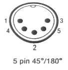
You can use practically any kind of connector for the 0-10V control input for the dimmer. I used a 5 pin DIN connector on my prototype. Suitable pin arrangement for 5 pin DIN connector is following:
Pin 1 = Channel 4
Pin 2 = Ground (common for all channels)
Pin 3 = Channel 1
Pin 4 = Channel 3
Pin 5 = Channel 2
Here is the pinout of 5 pin DIN connector:

Output connectors
The prototype I build used 4 grounded IEC female connectors and one 8 pin round Bulgin P552 connector (lighting industry standard). Both of those connectors are connected in parallel, so it is possible to use either one one them or both of them at the same time.
Connection of the IEC connectors:
IEC      Place in circuit

LIVE     Output from channel triac on triac card
NEUTRAL  Neutral bar on triac card
GROUND   Wired to the mains input connector ground
Wiring for 8 bin Bulgin connector:
1   Ground
2   To channel 1 output triac
3   To channel 2 output triac
4   To channel 3 output triac
5   To channel 4 output triac
6   Not connected
7   To neutral bus
8   To neutral bus
Circuit construction
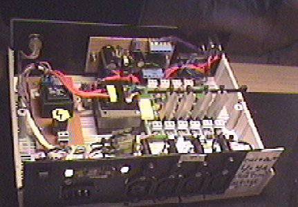
The whole circuit is built inside a convient plastic box which was previously used for some old outdated project. The picture below shows the internal construction of the dimmer unit.

On the to of the picture you can (fron left to right) see power on indicator light, main controlling board (ramp generator+voltage comparators) and on the right you can see the 0-10V input connectors.
On the middle section on the picture (from left to right) you can see the following items: 9VDC power supply for triac card, 12VAC transformer for main control board and on the right the triac switching card (the one with four heatsinks).
On the bottom of the picture you can see the power input connector, filtering capacitor, output connectors+protective fuses and the filtering coil on the right. All of the power connectors are 10A IEC connectors for the reason that bigger connectors (like SCHUKO mains sockets) don't fit nicely to the back panel of the circuit.
After I took this picture I have added the automatic resettable 10A main fuse and 8 pin Bulgin connector to the back panel of the dimmer. I added those for my convience. Now I can change or reset the fuses without opening the case. And one connector handling four lamps is very convient in cutting the mount of needed cables on the lighting system
The circuit construction has beed used for controlling up to 2 kW of lights for many hours without any heating problems. If in any doubt with our circuit cooling needs please add an overheating protector to the circuit.
Circuit safety and compliance
This circuit design has not been tested against any safety or EMC standards in effect in Europe which would apply to this product. I have tried to make this circuit design to be safe and not to cause too much interference to other equipments.
The electrical safety of the circuit is provided by using adequate wiring (well insulated 1.5 mm^2 for main current carrying wires, 0.75 mm^2 for other mains wires), adequate insulation (insulted wires, plastic case), ehough distance on the circuit board between tracks), using proper fuses and good enough mechanical construction. The plastic case provides mechanical protection (not possible to touch mains carrying parts) and provides double insulation. The mains switching parts it done using a ready made design (Velleman kit) which is designed for this kind of appications, so it's construction should be safe (it looked a good design). My own other parts were operated by low voltage provided by good quality mains transformers (doulby insulated). Overheating protection is provided by providing large enough heatsinks for triacs and using case with some ventilation holes and testing the whole system with hours of full load (no too much heating noticed in any tests).
EMC issues are another story, which are not to be tested easily. I am not completely sure under which EMC standard the circuit would fall-in, but IEC/EN61000 might be that. According some disuciions in usenet news on those topics it seems that general light dimmers up to 1 kW do not need to be tested for power harmonics and same applies to professiona light dimemrs up to 3680 W. So the power harmonics issue should be handled right.
Commercially made light dimmers need to meet conducted emission standards. EN55015 standard set the limits for conducted emission on dimmer products. The conducted emissions are mostly harmonics and can exist up to megahertz frequecny region. I use one choke and filter capacitor on the power input approach to reduce emissions conducted throught the power input to the mains input wire (propably the longest wiring connected to the equipment). The output does not have any specific filtering in them. The coil in the input limits somewhat the current rise on them, but I don't know if the emissions there are within the limits set by the standard or not.
For example NJD electronics seem to list the following standards for one ot their light sequencer circuit: EN60065 (European Standard for Electrical Safety) and EN55103 (European Standard for Electromagnetic Compatibility) for example for a light sequencer circuit. Some DM1000x rack mountable dimmer from NDJ Elecronics lists the following standards: EN60439 Part 1 (European Standard for Safety of Electrical Switchgear), EN55015 (European Standard for Electromagnetic Compatibility) and EN60297 (Fascia panel dimensions).
Using the circuit
I have used this circuit vith quite wide variety of the lights. The circuit is designed to work with normal light bulbs. The circuit is not designed to operate with highly inductive loads, but seems to be able to at least somehow control some halogen light driven by a normal transformer.
Because the circuit takes a standard 0-10V input it can be used with practically any professional lighting desks which has standard 0-10V output.
If you are looking for something cheap, then you can build my 4 channel simple analogue light controlling desk which has performed very well with this dimmer circuit (propably even install one on the fornt panel of the case). The dimmer rack has been in use in some parties controlling up to 1600 watts of lights. At that load the heating of the dimmer was not a problem at few hours of constant use at near full power output.
Known features and problems
I have tested the dimmer circuit with wide variety of different loghting loads and dimmer seemed to work quite well with them. I have successfully dimmed also inductive loads like low voltage halogen lighting with transformer in them. The only annoying feature on my first dimmer prototype (no R5 and C1 filter) was that on some cases very capacitive or inductive loads have caused some false operation on nearby dimmer channels. I have found (quite rarely though) that certain highly inductive loads when connected to one channel and dimmed to certain level can cause other channels normally set off to turn on. This hasl also happened few times with channesl which have had long cables connected to them but no light bulbs in them. When I have been dimming normal light bulbs I have not noticed any problems with this version.
After experimenting seems that that the triacs might need some extra filtering on output side to avoid this kind of problems with certain problematic loads. WIth experimenting and looking at other dimmer desing I decided to add R5 and C1 to the circuit to add tis filtering. It seems to have solve the problem and work otherwise well.
Modifications I have done later to my unit
I have done several modifications / additions to the circuit I built. The basic circuit operation has stayed the same, but there are few things that had made the circuit easier to use.
First thing was to replace the 10A mains fuse, that was originally placed inside the circuit (hard to change) with a 10A resettable circuit breaker. I though this would be more convient as the main overload protector.
In the beginning the circuit had only IEC output connectors. I added a 8-pin Bulgin P552 connector to the circuit back panel. This connector allows connection of all four output channels with only one connector. This allows this dimmer to be used with disco light setups that use this connector. This 8-pin Bulgin connector is just simply wired electrically in parellel with the existing output connectors.
Modifying the circuit for 120V 60 Hz operation
Due the large number of request for information how to modify the circuit for 120V 60 Hz AC operation, I have included this chapter to answer most of the questions so you don't need to mail me to ask for details.
To use the circuit with 120V 60 Hz AC you will have to do atleats the following modifications:
- Ramp generator
- Change transformer to a model with 120V AC primary and 12V AC secondary and use suitable fuse for it
- Tune the R5 using the same instructions as for 50 Hz operation, 60 Hz operation needs a different position for R5, but the tuning range is wide enough for this and same tuning procedure applies after you have connected the dimmer to 60 Hz power.
- Voltage comparators
- No modifications needed
- Triac output card
- Velleman K2634 four channel triac card is designed to operate with any voltage from 12V to 230V, so no modifications for this is needed
- 9V power supply for triac card
- You need to use 120V to 8 V AC transformer
- No need to change fuse rating
- Mains power section
- No changes needed here
- Output connectors
- No changes needed here unless you want to use some other kind of connector for output
There is no guarantee that those were the all necessary modifications or entirely the right ones. They are my quite quick analysis what needs to be done. I have not tested those modifications and there is no guarantee that that folloging those gives you any usable or safe results.
For 120V operation please note that the maximum current ratings still apply to this circuit, so the maximum total power is 1200W and per channel power is 480W when you operate at 120V AC.
Tomi Engdahl <[email protected]>


