


Stroboscope trigger circuits
This page contains some information on circuits which can be used for triggering stroboscopes from external circuits. The circuit here are designed to be integrate to strboscope circuits so that they can triggered using external trigger pulse. The standard trigger pulse used in professional stroboscope controllers is 3-10V pulse. If you don't already have a suitable controller, you can built one based on my stroboscope controller design.
Safety considerations
Stroboscope circuit use lethal voltages, so you must be very careful when operating with them. When the stroboscopes are triggered using an external signal, then there are some extra safety things to consider. The safest way is to provide a complete galvanic isolation of few kV between the trigger input and the stroboscope circuitry. This isolation can be done using and optoisolator or transformer isolation.
CAUTION - high voltage of strobes can cause a nasty and possibly fatal shock. The energy storage capacitor can retain dangerous high voltage after power is removed from the board.
Optoisolated trigger circuits
This circuit takes 10V trigger pulse to trigger a triac which connect the points A and B together. This circuit can be placed to almost any stroboscope circuit in place of the trigger switch or the trigger triac.
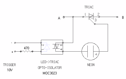
The circuit works in the following way:
- The +10V trigger pulse enters MOC3023 optoisolator
- The output of the optoisolator starts to conduct because of the current which starts to flow though optoisolator output and NEON bulb
- When the TRIAC starts to condict the triggering of the stroboscope happens
- At the same time when the TRIAC conducts, the current on the circuit formaed by NEON bulb and MOC3023 stops to flow
- When the triggering capacitor is discharged the TRIAC itself stops to condict
The isolation between the trigger signal and the stroboscope circuit is provided by MOC3023 optoisolator, which can withstand pulsed up to 7500V. This isolation level is more than dequate in typical applications. If you want really anjoy this kind of high voltage isolation you must keep in mind to keep enough clearance in the circuit board between the input and output pins of the MOC3023 optoisolator.
Transformer isolated trigger circuits
Another option to provide the isolation between trigger signal and the stroboscope is to use transformer isolation. In this approach the trigger pulse is fed to the gate of the TRIAC or thyristor though a transformer. There are amny types of transformers which can be used, but the best selection for those would be a pulse transformer which is designed for triggering triacs and provides the necessary isolation levels (at least few kV).
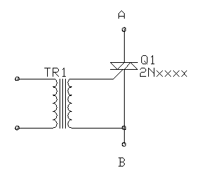
I have used this kind of circuits in triggering some of my stroboscope designs. I have used various types of TRIACs and transformers for implementing this signal.
Because the input of a typical pulse transformer is low resistance, I have put a 470 ohm resistor in series with the pulse transformer promary to limit the current which flows to this circuit. Using the 470 ohm resistor, the current using 10V input signal is in oder of 20 mA. When the input resistance is 470 ohms, a tpyical strobo controller can easily trigger few of this kind of circuits.
If you are modifying an actual stroboscope light, my 12V strobocope circuit will give you some idea how to use a transformer isolated trigger circuit in a real stroboscope circuit.
Selecting the TRIAC
The typical voltages applied to the trigger transformers in typical triac circuits are in order of 100-300V. This means that you have to select a TRIAC which can handle at least 400V voltage. I don't know what is the minimum rating of the triac suitable for the triggering circuit, but I have had very good results with the TRIACs which can handle at least few amperes of continuous current. It is also a good idea to select a sensitive gate TRIAC so you can trigger the TRIACs reliabily with the low currents available in the circuits described above.
Using ready made module
Kemo Electronics makes a module M006 which is ment to be single channel 1000W light organ for light powered with 23V AC. That module is packed to a matchbox size plastic box and has a trigger and audio signal isolation transformer in it.
Besides being an easy to use light organ module (you just need to add one potentiometer to make it work), this box can be used as general purpose triggering circuit for stroboscope.
When you connect the output connectors of the module to the stroboscope circuit (same way as the circuits descrbed above) you get it work there. The triggering of the circuit works by just feeding a trigger pulse to the isolated signal input of the module. I have foudn out that standard 3-10V trigger pulses work nicely with the module when you put a 470 ohm resistor in series with the module input and feed the trigger pulse to this system. This circuit worked quite well with the resitor only, was a little but to sensitive to the noise in the trigger cable (flashed on noisy enviroments where there are other light controllers around by itself randomly). To help this problem I added the 333 nF capacitor to filter out very small noise spikes to not to trugger the stroboscope. The real trigger pulses from controller will still trigger the circuit without any problems.
The picture below shows the connections:
     ---470ohm--+--+  +----------
                |  |  |
trigger   33nF === |  |          to stroboscope circuit
                |  |  |
     -----------+  |  |  +-------
                |  |  |  |
             +-------------+
             |             |
             | M006 module |
             |             |
             |             |
             +-------------+
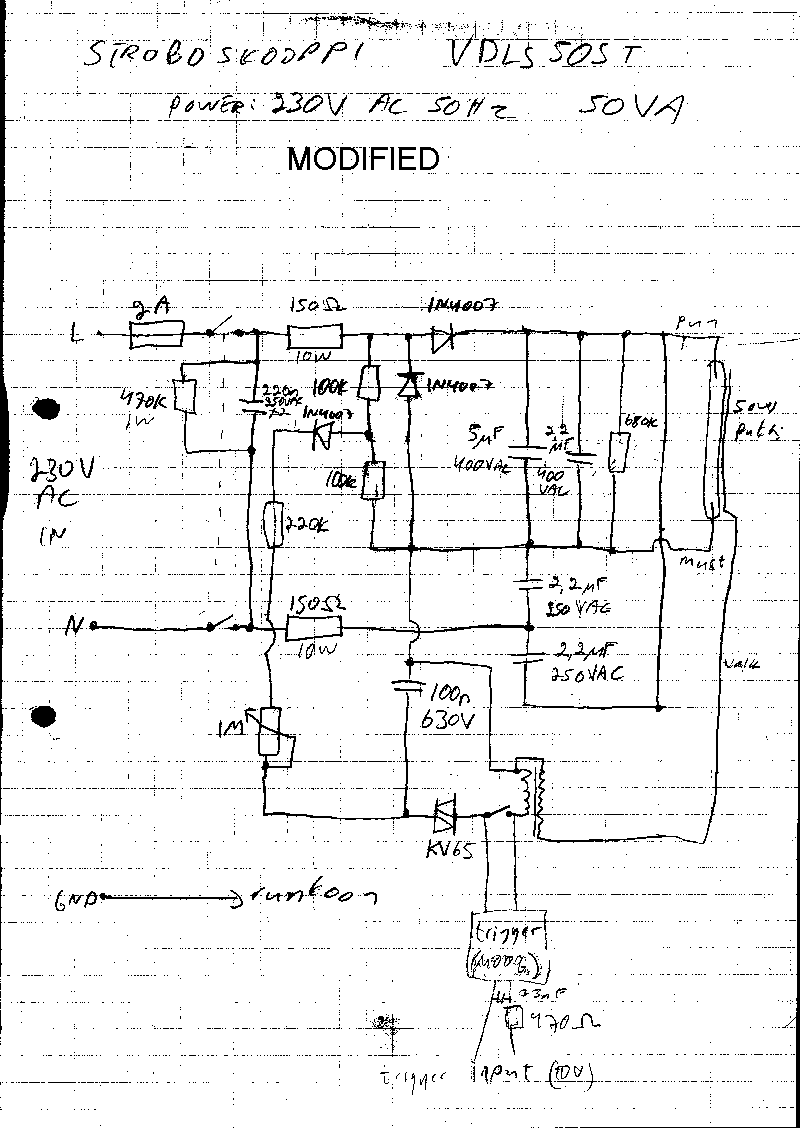
Kemo modules are sold in Finland by Bebek. The module costs around 60 finnish marks (around 12 US dollars). The module has weorked nicely when I have intrgrated it to one commercial 50W stroboscope (model name VDLS50ST) which did not originally have an external trugger signal input. If you are interrested to see how I did that modification take a look at original circuit diagram and modified circuit diagram.
Connecting the circuit to stroboscope or flash light
The idea is to connect the circuit described above to existing trigger circuitry of the camera flash or stroboscope so that is in parallel with an existing trigger element (thyristor, switch or similar) or replaces it. The actual impelementation depends on the actual stroboscope circuit you are trying to modify.
If you re modifying a flash light which has a mechanical trigger button, you can just connect the trigger circuit in parallel with the existing button which closes when pressed. In this case you can trigger the light by pressing the button or feeding a pulse to the strobo triggering circuit. In storobscope example circuit at http://www.intermarket.net/~don/samflash.html) you just would connect the trigger circuitry in parallel with existing shutter switch.
Safety considerations
The circuits itself should not cause any serious safety problems when properly constructed. The safety considerations come from the stroboscope circuit you are added those circuits to. Typical stroboscope circuits are directly connected to mains voltage and have capacitors which have leathal amount of high voltage stored them.
The trigger circuit must be constructed so that those dangerous voltages will not in any case get to the trigger output. This means that the circuit must be constructed carefylly and in a safe way. This means that the components must be well secured on their place, there is enough clearance between the high voltage and low voltage parts of the circuit, the circuit itself is securately mounted to the system and dangerous parts are properly isolated. Make a very careful visual inspection and measure the circuit carefully before even thinking of adding it to any stroboscope circuit. When you add the circuit to the storboscope circuits be exactly sure what you are doing and what are the safety implications of adding this kidn of circuit to the stroboscope. When you do the installation, be sure that the stroboscope is diconnected from the power source and all capacitors are discharged, before you even think of touching the circuit. When you make the connection, do it carefully and double check everything, before testing.
And remeber that there is no guarantee that those trigger circuits will work in your particular stroboscope circuits.
Tomi Engdahl <[email protected]>