


Sega 3D glass interfacing
This documents ties to clear out one method for connecting Sega 3D glasses to PC serial port for cheap PC virtual reality. This who do no not know what those Sega 3D glasses are, here is a description:
What are Sega 3D glasses ?
Sega designed special glasses for it's video game console to be able to produce 3D video games. Those glasses used LCD shutter method for producing 3D images. In this method the picture is snown to different eyes after each other. The LCD panels in front of both eyes are controlled so that one eye sees one screen image and the other eye sees the second image etc. With normal TV it was possible to show 25 or 30 images per second (depending on TV standard used) to both eyes. The image flickers quite much, but gives well noticable 3D effect. 3D games for sega game consoles did not sell very well and Sega dropped those glasses from it's product lines.
How they are used in PC VR ?
Ever since the Sega 3D glasses are used in many home virtual reality projects. There is free software support for those glasses in some nice VR programs (for example rend386). One of the problem for home experiments have been to figure out how to connect those glasses to PC. There have been two approaches used commonly: serial port and parallel port. For connecting the glasses to those PC ports, the small adapater box (made for Sega game console) is practically useless. The home VR experiments had to devellop their own circuit. This one is the most commonly seen circuit. It is floating in many places and even published (in the form of following document) in at least one small VR magazine, but there is no knowledge who originally designed this circuit.
Circuit to connect SEGA 3D glasses to RS-232 port
       RS-232
     DB25 / DB9
                                                   10K
RTS   4      7  Switching signal +/- 10V  --------vvvvv--+
                                                         |
                                                         |
GND   7      5  Ground ----+-------------+--+---------+--|----+
                           |             |  |         |  |    |
                           |             |  +-|>|--+  |  |    |
                           +--|>|--+    ---        |  |  |    |  Transistor
                                   |    ---  22 uF |  |  |    |   2N2222
                                   |     |         |  |  |  +-+---------+
                                   |     |         |  |  |  | Emitter   |
                                   |     |         |  |  |  |           |
DTR  20      4  Vdd +10V --|>|-----+-----+         +--|--+--+ Base      |
                                         |            |     |           |
                              +--+--+--+-+-vvvvv---+--|-----+ Collector |
                              |  |  |  |    10K    |  |     |           |
                              |  |  |  |           |  |     +-----------+
                      +-------+--+--+--+-----------+--+--+
                      |       1  9  13 14          5  7  |
                      |                                  |
                      |   RCA CD 4030 Quad XOR gate      |
                      |                                  |
                      | 2 11  12       3  6  8   10   4  |
                      +-+--+---+-------+--+--+----+---+--+
                        |  |   |       |  |  |    |   |
                        +--+   |       +--+--+    |   +--- Outside of jack
                           |   |             |    |
                           |   +-vvvvv-+     |    +------- Middle of jack
                           |      22K  |     |
                           |           |     +------------ Centre of jack
                           +-vvvvv-----+     |
                              22K      |     |
                                      ---    |
                              .01 uF  ---    |
                                       |     |
                                       +-----+
This is my best attempt at a rendition of the circuit which connects my SEGA glasses to my AT. I didn't design the circuit -- I'm a software rather than hardware person. In fact I barely understand it -- as far as I can tell, the .01uF capacitor & the 22K resistors act as a delay. The outputs of the XOR gates feed back into their own inputs, thus producing an oscillator. The "jack" mentioned in the diagram is the mini-jack which is connected as standard to the glasses. "Centre", "middle", and "outside" relate to the external connections, looking at the thing end-on.
Disclaimer: The circuit diagram above may be entirely wrong. My description may be wrong.
Caveat emptor... to paraphrase the standard software licence agreement: It's as good as I can get it. If it doesn't work or blows up your computer or your glasses and blinds you for life, I'll give you back all the money you paid me.
Good Luck... Frank.
Circuit description
The circuit consistos of one oscillator made of two XOR gates, two resistors and one capacitor. This oscillator generates about 400 Hz frequency for driving the LCD panels (the LCD panels muts be driven with AC signal!). The oscillator output is fed to centre (tip) of the LCD glass jack. The same output is fed to the middle contact of the jack inverted. The signal going to the outside of the jack is inverted or non-inverted output of the oscillator depending of the switching signal state. This causes one of the LCD panels to be black and other to be clear (which is black and which is white is controlled by swithcing signal state). Look at the signal diagram below to get to understand the details.
             _   _   _   _   _   _   _   _   _
CENTRE     _| |_| |_| |_| |_| |_| |_| |_| |_| |_
           _   _   _   _   _   _   _   _   _   _
MIDDLE      |_| |_| |_| |_| |_| |_| |_| |_| |_|
           _   _   _   _   _     _   _   _   _
OUTSIDE     |_| |_| |_| |_| |___| |_| |_| |_| |_
                               _________________
Switch     ___________________|
Signal
For those who are interrested, one LCD panel of the LCD glass is
wired between centre (tip) and outside of the jack. The other panel
is wired between middle and outside of the jack.
My version of the circuit
When I built the circuit descripbed above, I made a few changes to the circuit. First I replaced the 2N2222 transistor with BC5547, which is easier to find in Europe. Other changes included replacing the 22 kohm resistor in the oscillator circuit with 47 kohm trimmer. This made it possibile to fine tune the oscillator frequency to get the best results from the circuit (it is a good idea to keep the trimmer is about the center position). And I also drove the circuit schematic to a form which is much easier to understand.
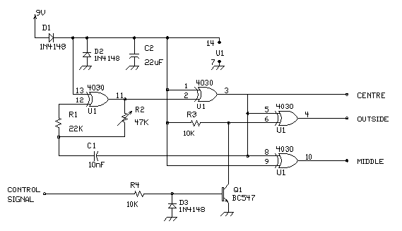
The control signals and power are taken in the same way as in the asciiversion of the circuit: DTR gives the power to the circuit and RTS pin controls the switching signal.
You can easily build the circuit to a small project box and install a 3.5 mm stereo jack for the 3D glasses or you can wire the glasses directly to the circuit uusing following wiring diagram of the sega 3D glasses:

Using SEGA 3D glasses to view field-sequential stereo video signal
Sega 3D glasses can be also used with normal VCR to view field sequential stereoscopic video material. Field sequential VCR signals is stored so that the every odd video field is for one eye and every even video field is for other eye. To view this material using Sega 3D glasses you need a special box which exracts the odd/even field information from the video signal. This can be easily accomplished using LM1881 chip in the following circuit:
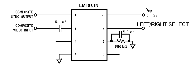
You can connect this circuit to the circuit presented above very easily. Just connect LEFT/RIGHT SELECT signal output to the serial adaptor CONTROL SIGNAl input and the video input of this circuit to the VCR composite video output. You can power this circuit from the same external 9V power source as the serial interface. This circuit works nicely with standard PAL and NTSC video signals. This circuit has problems in detecting the ODD/EVEN field information from some computer generated interlaced picture material, because that material usually lacks some of the syncronization pulses found in standard PAL/NTSC signals.
Control system used in commercial 3D glass interfaces
PC3D serial port interface
BD25  Name   Function
----------------------------------------------------
 4    RTS    Glasses Control: Low=Right active (dark)
20    DTR    Power +
 7    GND    GND
V105 serial/parallel interface
BD25  Function
--------------------------------------------------
 4    RTS
20    DTR
 7    GND Serial
 4    D2
 5    D3
25    GND Parallel
 3    D1
 2    D0
Tomi Engdahl <[email protected]>