


ePanorama.net - Joysticks
Digital joystick connector pinouts
Most old home computers used digital joysticks similar to the joysticks used in Atari 2600 video game. This 9 pin joystick interface became a de-facto standard in early home computer industry.
Basic Atari joystick interface
_________________
\ o5 o4 o3 o2 o1/
 \ o9 o8 o7 o6 /
  \___________/

Pin Joystick

1   Forward
2   Back
3   Left
4   Right
5   -
6   Button 1
7   +5V *
8   GND
9   -
The +5V power is optional. Some computer supply it and some don't. +5V power is usually only used for special functions like autofire. Here is the pinout above drawn in easy to understand format:
      +---------> Right
      | +-------> Left
      | | +-----> Down
      | | | +---> Up
      | | | |
  _____________
5 \ x o o o o / 1
   \ x o x o /
  9 `~~~~~~~' 6
       |   |
       |   +----> Button
       +--------> Ground
Typical controller connectors used in home computers
In the era of 8-bit machines, there was something like de-facto standard for joystick ports. All joystikc ports were digital, and all used D-Cannon 9 pin connectors (db9) wired in the "Atari" way:
      +---------> Right
      | +-------> Left
      | | +-----> Down
      | | | +---> Up
      | | | |
  _____________
5 \ x o o o o / 1
   \ x o x o /
  9 `~~~~~~~' 6
       |   |
       |   +----> Button
       +--------> Ground
Because of that, a single joystick could be used without
hassle on Atari (130, 800XE, 800XL, 2600, 7200), Amiga, Commodore C64,
Amstrad CPC, Sinclair ZX Spectrum and many other machines. That's why these
joysticks are sometimes called "Multisystem".
However, as time passed, extension to this standard developed, and these were not compatible with each other (drawings based on Linux Joystick parport drivers v1.2 BETA documents written by Vojtech Pavlik 1998):
  Atari 130, 800(XL/XE)                    MSX

                                         +-----------> Power
      +---------> Right                  | +---------> Right
      | +-------> Left                   | | +-------> Left
      | | +-----> Down                   | | | +-----> Down
      | | | +---> Up                     | | | | +---> Up
      | | | |                            | | | | |
  _____________                        _____________
5 \ x o o o o / 1                    5 \ o o o o o / 1
   \ x o o o /                          \ o o o o /
  9 `~~~~~~~' 6                        9 `~~~~~~~' 6
       | | |                              | | | |
       | | +----> Button                  | | | +----> Button 1
       | +------> Power                   | | +------> Button 2
       +--------> Ground                  | +--------> Output 3
                                          +----------> Ground

       Amstrad CPC                         Commodore C64

                                         +-----------> Analog Y
      +---------> Right                  | +---------> Right
      | +-------> Left                   | | +-------> Left
      | | +-----> Down                   | | | +-----> Down
      | | | +---> Up                     | | | | +---> Up
      | | | |                            | | | | |
  _____________                        _____________
5 \ x o o o o / 1                    5 \ o o o o o / 1
   \ x o o o /                          \ o o o o /
  9 `~~~~~~~' 6                        9 `~~~~~~~' 6
       | | |                              | | | |
       | | +----> Button 1                | | | +----> Button
       | +------> Button 2                | | +------> Power
       +--------> Ground                  | +--------> Ground
                                          +----------> Analog X
And there were many others. Some manufacturers even added analogue joystick and/or paddle controller function to the same connector:
_________________
\ o5 o4 o3 o2 o1/
 \ o9 o8 o7 o6 /
  \___________/

Pin Joystick       Analog joystick   Paddle

1   Forward        Button 3*         -
2   Back           -                 -
3   Left           Button 1          Left Button
4   Right          Button 2          Right Buttom
5   -              Pot X             Right POT
6   Button 1       -                 -
7   +5V*           +5V               +5V
8   GND            GND               GND
9   Button 2*      Pot Y             Left POT

* those pins are optional
For example Commodore VIC20 and Commodore 64 computers supported those paddle controllers.
Typical "Atari style" joystick circuit diagram
The joystick industry had de-facto wiring for wires used in joystick cables. Here is the de-facto wiring used in Commodore 64 (many other manufacturers used same coloring):
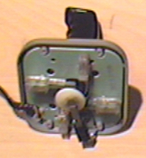
Pin Color    Function
 1  White    Up
 2  Blue     Down
 3  Green    Left
 4  Brown    Right
 5           no contact
 6  Orange   Fire button
 7  Red      +5V, max. 50 mA
 8  Black    Ground
 9           no contact
There are many ways to contruct a digital joystick. Some of the cheapest joystick just have mechanics of cheap buttons, where the better ones usually utilize microswitches. On the picture below you can see WICO Boss joystick construction. It uses five switches which are built from two springs which touch each other when stick is moved or button is pressed.
There is a picture of original Atari 2600 stick and what's inside it available on the web at http://www.netaxis.com/~petebuilt/videogames/26insid.html.