


For Spanish version click here
Parallel port interfacing made easy: Simple circuits and programs to show how to use PC parallel port output capabilities
Copyright Tomi Engdahl 1996-2010
Index
- Introduction
- How to connect circuits to parallel port
- Control program for DOS (and Win9x)
- Parallelport programming in DOS
- Parallel port controlling in Windows programs
- Parallel port controlling in Linux
- Controlling parallel port through web
- Controlling some real world electronics
- Building your own relay controlling circuits
- Mains power controlling with parallel port
- Compact 8 channel output driver
- Links to parallel port output circuits
- Ready made control software
- Reading the input pins in parallel port input pins
- Parallel port software registers technical summary
- Notes on parallel port operation during computer boot-up
- Notes on different parallel port versions
- Notes on PCI bus parallel port cards
- Notes on USB parallel port adapters
- Other documents worth to check
Introduction
PC parallel port can be very useful I/O channel for connecting your own circuits to PC. The PC's parallel port can be used to perform some very amusing hardware interfacing experiments. The port is very easy to use when you first understand some basic tricks. This document tries to show those tricks in easy to understand way.
WARNING: PC parallel port can be damaged quite easily if you make mistakes in the circuits you connect to it. If the parallel port is integrated to the motherboard (like in many new computers) repairing damaged parallel port may be expensive (in many cases it it is cheaper to replace the whole motherborard than repair that port). Safest bet is to buy an inexpensive I/O card which has an extra parallel port and use it for your experiment. If you manage to damage the parallel port on that card, replacing it is easy and inexpensive.
NOTE: The I/O port level controlling details here has proven to work well with parallel ports on the PC motherboard and expansion cards connected to ISA bus. The programming examples might not work with PCI bus based I/O cards (they can use different hardware and/or I/O addresses, their drivers make they just look like parallel ports to "normal" applications). The programming examples do not work with USB to parallel port adapters (they use entirely different hardware, their drivers make them to look like normal parallel port to operating system "normal" applications).
DISCLAIMER: Every reasonable care has been taken in producing this information. However, the author can accept no responsibility for any effect that this information has on your equipment or any results of the use of this information. It is the responsibly of the end user to determine fitness for use for any particular purpose. The circuits and software shown here are for non commercial use without consent from the author.
How to connect circuits to parallel port
PC parallel port is 25 pin D-shaped female connector in the back of the computer. It is normally used for connecting computer to printer, but many other types of hardware for that port is available today.
Not all 25 are needed always. Usually you can easily do with only 8 output pins (data lines) and signal ground. I have presented those pins in the table below. Those output pins are adequate for many purposes.
pin function
 2   D0
 3   D1
 4   D2
 5   D3
 6   D4
 7   D5
 8   D6
 9   D7
Pins 18,19,20,21,22,23,24 and 25 are all ground pins.
Those datapins are TTL level output pins. This means that they put out ideally 0V when they are in low logic level (0) and +5V when they are in high logic level (1). In real world the voltages can be something different from ideal when the circuit is loaded. The output current capacity of the parallel port is limited to only few milliamperes.
Here is a simple idea how you can connect load to a PC parallel port data pins.
        Dn Out ------+
                     |+
  Sourcing         Load (up to 2.6 mA @ 2.4 v)
                     |-
        Ground ------+
This is not the only way to connect things to a parallel port.
The parallel port data pins are TTL outputs, that can both sink and source current. In ordinary parallel port implementations the data outputs are 74LS374 IC totem-pole TTL outputs which can source 2.6 mA and sink 24 mA.
Regular TTL outputs basically consist of a two "stacked" transistor in series between +5 volts and ground, with the output coming from the connection between them. This is called a "totem pole output". At any given time one of these transistors is conducting and the other is not. To pull the output "high", the transistor from +5 to the output conducts (H), which "sources" positive current from the output to ground (that is, an external device between the output and ground will get power). To pull the output low, only the lower transistor (L) conducts, "sinking" current to ground; an external device between +5 volts and the output can be energized.
         +5
        /    |
    ---H on  V
        \      -->
         |________        TTL output on = 1 = high, "sourcing" current
         |   out  \
        /         / |
    ---L off      \ V
        \_________/
        Gnd


       +5_________
        /         \
    ---H off      / |
        \         \ V
         |________/      TTL output off = 0 = low, "sinking" current
         |  <-- out
        /
    ---L on |
        \   V
        Gnd
The outputs are designed so that they give at least 2.4V at 2.6 mA load. This 2.6 mA figure is for ordinary LS-TLL circuits used, the LSI implementations used in many computers can give more or less. For example quite popular (few years ago) UM82C11-C parallel port chip can only source 2 mA.
Simple current sinking load connection:
        Dn Out ------+
                     |+
  Sourcing         Load (up to 2.6 mA @ 2.4 v)
                     |-
        Ground ------+
When taking current from PC parallel port, keep the load low, only up to few milliamperes. Trying to toke too much current (for example shorting pins to ground) can fry the parallel port. I have not killed any parallel port (yet) in this method, but I have had in cases where too much load has made the parallel port IC very hot. Be careful.
If you have an external +5 volt supply, you have another option for connection: use the Data Out pins to sink up to 24 mA from your +5 volt supply. This can be made with a circuit like this:
                     +------------------------------- (+5 v)
                     |+
   Sinking         Load (up to 24 mA @ 4.2v)
                     |-	     Power Supply
        Dn Out ------+

        Ground -------------------------------------- ( Gnd)
The load gets power then you have external +5V on and the printer port data pin set to 0. This circuit gives you capability of of driving more current than the "sinking" approach. You need to be careful with this circuit, because with this circuit you can easily fry the parallel port if you do things wrong. My advice is to be very careful with this type of circuit and make sure that the external +5V power supply gets turned off when computer gets turned off (all printer ports might not like getting +5V though the load to printer port when they are not powere). The most convient source "external +5V" might be from same other port on your PC (USB, joystick, keyboard/mouse etc. port).
I have used mostly "sinking" type circuits and this article is concentrated on using them.
Simple LED driving circuits
You can make simple circuit for driving a small led through PC parallel port. The only components needed are one LED and one 470 ohm resistors. You simply connect the diode and resistor in series. The resistors is needed to limit the current taken from parallel port to a value which light up acceptably normal LEDs and is still safe value (not overloading the parallel port chip). In practical case the output current will be few milliampres for the LED, which will cause a typical LED to somewhat light up visibly, but not get the full brigtness.

Then you connect the circuit to the parallel port so that one end of the circuit goes to one data pin (that one you with to use for controlling that LED) and another one goes to any of the ground pins. Be sure to fit the circuit so that the LED positive lead (the longer one) goes to the datapin. If you put the led in the wrong way, it will not light in any condition. You can connect one circuit to each of the parallel port data pins. In this way you get eight software controllable LEDs.
The software controlling is easy. When you send out 1 to the datapin where the LED is connected, that LED will light. When you send 0 to that same pin, the LED will no longer light.
Here are two photos of circuit above I have built:
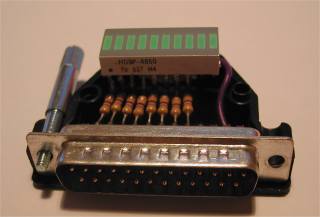
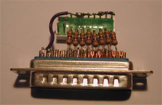
Pn those circuits I have wired the ground wire only to one ground pin (it works also well, you can use any of the ground pins).
Technical specifications of parallel port pins
The IBM specifications says accoding http://www.linux.com/howtos/IO-Port-Programming-6.shtml the following: The data output pins (pins 2-9) sink 24 mA, source 15 mA, and their high-level output is min. 2.4 V. The low state for both is max. 0.5 V. Pins 1, 14, 16, and 17 (the control outputs) have open collector drivers pulled to 5 V through 4.7 kiloohm resistors (sink 20 mA, source 0.55 mA, high-level output 5.0 V minus pullup). Non-IBM parallel ports probably deviate from this standard.
Warning: Be careful with grounding. You can break parallel ports by connecting devices to them when PC is powered on. It is not a good idea to short the pins to ground or +5V, this can damage the port. It might be a good thing to use a parallel port not integrated on the motherboard for things like this. (You can usually get a second parallel port for your machine with a cheap standard `multi-I/O' card)
Control program for DOS (and Win9x)
The following program is an example how to control parallel port LPT1 data pins from your software. This example directly controls the parallel port registers, so it does not work under some multitasking operating system which does not allow that. It works nicely under MSDOS. You can look the Borland Pascal 7.0 code (should compile also with earlier versions also) and then download the compiled program LPTOUT.EXE. This has worked nicely for me in DOS systems and Windows 95/98 systems. On recent testings this program has worked unreliably on some Windoes 2000 systems.
Program lpt1_output;

Uses Dos;

Var
   addr:word;
   data:byte;
   e:integer;

Begin
   addr:=MemW[$0040:$0008];
   Val(ParamStr(1),data,e);
   Port[addr]:=data;
End.
How to use the program
LPTOUT.EXE is very easy to use program. The program takes one parameter, which is the data value to send to the parallel port. That value must be integer in decimal format (for example 255). Hexadecimal numbers can also be used, but they must be preceded by $ mark (for example $FF). The program hoes not have any type of error checking to keep it simple. If your number is not in correct format, the program will send some strange value to the port.
NOTE: I have found out that this program does not work reliably on some Windows 2000 systems I have tested on this. I don't know what is causing this specific problem (other than you should not try to access hardware directly on Windows NT based system..). I have not tested this program with Windows XP.
Example how to use the program
LPTOUT 0
Set all datapins to low level.
LPTOUT 255
Set all datapins to high level.
LPTOUT 1
Set datapin D0 to high level and all other datapins to low level.
How to calculate your own values to send to program
You have to think the value you give to the program as a binary number. Every bit of the binary number control one output bit. The following table describes the relation of the bits, parallel port output pins and the value of those bits.
Pin     2   3   4   5   6   7   8   9
Bit     D0  D1  D2  D3  D4  D5  D6  D7
Value   1   2   4   8   16  32  64  128
For example if you want to set pins 2 and 3 to logic 1 (led on) then you have to output value 1+2=3. If you want to set on pins 3,5 and 6 then you need to output value 2+8+16=26. In this way you can calculate the value for any bit combination you want to output.
Making changes to source code
You can easily change te parallel port number int the source code by just changing the memory address where the program read the parallel port address. For more information, check the following table.
Format of BIOS Data Segment at segment 40h:
Offset  Size    Description
 08h    WORD    Base I/O address of 1st parallel I/O port, zero if none
 0Ah    WORD    Base I/O address of 2nd parallel I/O port, zero if none
 0Ch    WORD    Base I/O address of 3rd parallel I/O port, zero if none
 0Eh    WORD    [non-PS] Base I/O address of 4th parallel I/O port, zero if none
For example change the line addr:=MemW[$0040:$0008]; in the source code to addr:=MemW[$0040:$000A]; if you want to output to LPT2.
Instead of trying to read the address from the DOS information data block you can always use the I/O address fixed to source code. The LPT1 port is typically at I/O-address 378h or 3BCh.
To get to know the port address to use you can use for example the method: On modern Windows systems (I tested in Windows 2000) you can get to know the parallel port I/O addrss through device manager. First open the device manager (start - settings - control panel - system - hardware - device manager). Then select there the parallel port you are interrested from Ports (COM & LPT) section. With mouse right button you can get menu where you select Properties. From there select Resources where you should see a screen like this:
The details in this image are from the parallel port built into the motherboard of my PC.
Parallelport programming in DOS
The following examples are short code examples how to write to I/O ports using different languages. In the examples I have used I/O address 378h which is one of the addresses where parallel port can be.
The typical parallel port I/O addess configurations seen on PCs with ISA bus:
- LPT1: 3BCh, LPT2: 378h, LPT3: 278h
- LPT1: 378h, LPT2: 278h
- LPT1: 378h
The following examples are for DOS system (they might or might not work on other systems). The code examples are designed to be used with LPT1 port that resides in I/O address 378h.
Assembler
MOV DX,0378H
MOV AL,n
OUT DX,AL
Where n is the data you want to output.
BASIC
OUT &H378, NWhere N is the number you want to output.
C
outp(0x378,n);or
outportb(0x378,n);Where N is the data you want to output. The actual I/O port controlling command varies from compiler to compiler because it is not part of standardized C libraries.
Here is an example source code for Borland C++ 3.1 compiler:
#include <stdio.h>
#include <dos.h>
#include <conio.h>

/********************************************/
/*This program set the parallel port outputs*/
/********************************************/

void main (void)
{
clrscr();             /* clear screen */
outportb(0x378,0xff); /* output the data to parallel port */
getch();              /* wait for keypress before exiting */
}
Using DOS debug to access parallel port
DOS program Debug is a simple 8088 assembler that comes with DOS operating system (comes with DOS utilities on most modern WIndows systems as well). Debug allows debugging of simple 16-bit DOS applications (not useful to modern 32-bit Windows programs). Debug program has several built-in debugging tool commands, including commands to read and write I/O ports.
o- writes one byte of dat to the specified I/O port
SYNTAX o port value
port - specifies the port address. The port address can be an 8 or a 16 bit value.
value - specified the value to write to this I/O-port. This value is 8 bit value.

i- reads one byte of data from the specified I/O port
SYNTAX i port
port - specifies the port address. The port address can be an 8 or a 16 bit value.
Examples:
If you type

o 3bc ff

debug will output value ff (hex) to port 3bc (hex).

If you type

i 3bc

debug will display 1 byte of data from the parallel port.
Parallel port controlling in Windows programs
Writing programs to talk with parallel port was pretty easy in old DOS days and in Win95/98 too. We can use Inporb and outportb or _inp() or _Outp functions in our program without any problem if we are running the program on Dos or WIN95/98. But entering to the new era of NT clone operating systems like WIN NT4, WIN2000, WINXP, all this simplicity goes away.
Direct parallel port controlling in possible under Windows 3.x and Windows 95 directly from 16 bit application programs and DLL libraries. So you can use the C example above in Windows 3.x and Windows 95 if you make your program 16 bit application. If you want to control parallel port from Visual Basic or Delphi then take a look at the libraries at Parallel Port Central at http://www.lvr.com/parport.htm.
Direct port controlling from application is not possible under Windows NT and to be ale to control the parallel port directly you will need to write some kind of device driver to do this. You can find also this kind of drivers from Parallel Port Central and Inpout32.dll for WIN NT/2000/XP.
Driverlinx PortIO at http://www.driverlinx.com/DownLoad/DlPortIO.htm is a worth to check driver for accessing I/O ports directly under Windows 95/NT (works also well with Windows 2000). This free software comes with example programs (both executable and source code available) how to access I/O ports from Visual Basic and Microsoft Visual C programs.
The I/O Control Using Using Visual Basic web page at http://www.southwest.com.au/~jfuller/vb/vbout.htm describes how to make a simple Visual Basic application that controls PC parallel port.
If you are looking for a ready made software, then take a look at Kemo M125 kit web page at http://www.kemo-electronic.com/en/module/m125/. Kemo relay module M125 is designed for switching up to 8 different appliances, lamps or motors according to a computer program (up to 40V and loads up to 0,4A DC or 0,2A AC). The module is operated at the printer port LPT1 in the same way as my parallel port controlling circuit examples (in this module there is one solid state relay connected for each of those 8 data output pin on parallel port). Kemo M125 kit information page has control software available for download. Those software allows controlling of outputs manually and timed operation. Windows software runs in WIN9x, WIN2K and WINXP. There is also programming C source code example available.
Parallel port relay relay board kit described at http://electronickits.com/kit/complete/elec/ck1601.htm comes with Windows and DOS control software that can be downloaded at the kit page. This software runs at Windows 9x/2000/ME/XP. Information on DOS utilities can be found at http://www.qkits.com/serv/qkits/diy/pages/QK74.asp.
Parallel port monitors page at http://neil.fraser.name/software/lpt/ has programs that allow you to set and monitor parallel port pin states. The software is available for few different versions that work on Windows 98 / ME / NT / 2000 / XP and DOS / Windows 3.1 / 95 / 98 / ME systems. The software is written using Visual Basic and Euphoria programming languages and comes with source code.
Beyond Design PC Serial and Parallel Port Software and Interfaces software VBPortTest at http://www.beyond-designs.com/PC_ports.htm is an useful utility. VBPortTest parallel port utility is designed to help test and debug parallel port interfaces. Allows access to the three registers (data, status, and control) associated with the PC standard parallel port (SPP). The user can read and write the data and control registers. The program continually reads the status register (the status register is read-only) . Individual register bits are displayed on LEDs along with the hex value for the entire data register. In write mode, the user can toggle individual bits by clicking on the corresponding LED. Hex values can be entered on the keyboard. Bit, byte and strobed byte write modes are possible. Online Help with useful parallel port reference material includes signal descriptions and Centronics handshake timing waveform. VBPortTest is available for download as freeware. Windows 98, ME, and XP compatible.
If you want to do programming of parallel port in Windows with C/C++ then one way to go is to use using the inpout32.dll and the free borland C compiler. For more info, you can check out http://hytherion.com/beattidp/comput/pport.htm and http://csjava.occ.cccd.edu/~gilberts/bcc55.html. The second link was a very nice, step by step guide as to how to do things.
Standard Windows API interface
Standard Windows API for parallel port programming is targeted for sending out characters to printer onneced to parallel port. It is not designed for contrlling single pins on or off.
Using the parallel port for digital output can be made to work with the normal Windows API with a simple hardware hack. The main trick is to tie pins 11(Busy) and 12 (Paper Error) to ground. Otherwise, the hardware driver will think the printer it is talking to is busy or experiencing an error and will not output any data.
Just send one character to parallel port, and the Windows wii send the value of that character to printer port data pins, plus generate one pulse to strobe line. The port will maintain the last value written to it until another value is written or until the computer is powered down or new data is sent to port. If you output more than one byte at a time the driver will send them to the port in sequence and toggle the Strobe line (line 1) off and on for each byte. The timing involved varies somewhat from one computer to the next.
This means that in a Windows environment we can output data to the parallel port. You can send data even through Windows command line with copy command like this:
copy somefile.bin LPT1
This will send the contents of file somefile.bin to the parallel port. The value of the last byte in the file will be left as the state of the parallel port after the command execution.
Besides need for the hardware hack, there are other limitations on the Windows API method. Windows API does not have built in support for input operations nor reading back the last sent value. Even though the parallel port hardware supports it, the software driver does not.
Parallel port controlling in Linux
Linux will allow acess to any port using the ioperm syscall. Here is some code parts for Linux to write 255 to printer port:
#include <stdio.h>
#include <stdlib.h>
#include <unistd.h>
#include <asm/io.h>

#define base 0x378           /* printer port base address */
#define value 255            /* numeric value to send to printer port */

main(int argc, char **argv)
{
   if (ioperm(base,1,1))
    fprintf(stderr, "Couldn't get the port at %x\n", base), exit(1);

   outb(value, base);
}
Save the source code to file lpt_test.c and compile it with command:
gcc -O lpt_test.c -o lpt_test
The user has to have the previledges to have access to the ports for the program to run, so you have to be root to be able to ron this kind of programs without access problems. If you want to make a program which can be run by anybody then you have to first set the owner of the program to be root (for example do compilation when yhou are root), give the users rights to execute the program and then set the program to be always executed with owner (root) rights instead of the right of the user who runs it. You can set the programn to be run on owner rights by using following command:
chmod +s lpt_test
Notes on source code: Some people have reported that for some reason this code does not work on theuir systems. If you have problems in getting this to work, try tho following chagest to code: replace the lines "#include <unistd.h%gt;" and "#include <asm/io.h>" with line "#include <sys/io.h>" and then replace line "#define base 0x378" with "#define base 0x0378".
If you want a more useful program, then download my lptout.c parallel port controlling program source code. That program works so that you can give the data to send to parallel port as the command line argument (both decimal and hexadecimal numbers supported) to that program and it will then output that value to parallel port. You can compile the source code to lptout command using the following line to do the compilation:
gcc -O lptout.c -o lptout
After you have compiled the program you can run it easily. For example running ./lptout 0xFF will turn all data pins to 1 and running ./lptout 0x00 will turn all data pins to 0.
In some systems the I/O port addresses can be different than one used in my example program. In this case you need to modify the address in #define base line. There are different ways to know the port address. First you could try your graphical configuration tools to look for this information. Those tools and how to use them vary quite much between different Linux distributions. There are also some command line tools you can try:
- In many linux systems you can get information on I/O devices and ports they use with command "cat /proc/ioports". This list should include your parallel port or parallel ports in it. The first parallel port (port in motherboard) typically has name parport0. There are some cases where you might not see your device in your list or sometimes you see the sama name twice (usually the first one is the right one).
- In some systems you might have additional parallel ports on I/O cards in the PCI bus. In many new Linux systems you can run "lspci -v | more" to get information of each device on your PCI bus (this should tell make and model, interrupt and port and memory block assignments).
I have also written a more feature rich program to control. portconrol is a simple general purpose I/O port control program for Linux. It allows you to write and read the supported I/O ports. The software allows writing specified value to port, reading value at given I/O address and printing it out to screen in different formats and bit-level manipulation of the port data. The portcontrol software is available as portcontrol.tar package that includes the source code, instructions for compiling/installing and instructions for use. For more details check the README and the portcontrol.c source code.
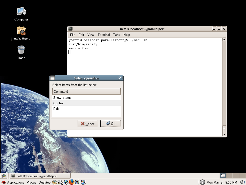
Simple Linux GUI
I have written a simple GUI program example for controlling parallel port on Linux system. My simple parallel port control GUI is written in such way that it allows you to control parallel port pins. To see what it looks check the screenshot.
This simple control GUI is written in such way that it runs on both GNOME and KDE windowing systems. The program is written as bash script that uses zenity and/or kdialog programs to do the GUI menus itself. The program expects that you have the portcontrol program installed in your Linux system to /usr/local/sbin/portcontrol with suitable rights that you can run it.
The program is intended to be a simple example that you can modify for your own uses. Just download menu.sh and start testing yourself.
Programming tips
If you want to learn more about I/O port programming I recommend to read Linux I/O port programming mini-HOWTO. Here are few tips from that document:
- Routines for accessing I/O ports are in /usr/include/asm/io.h (or linux/include/asm-i386/io.h in the kernel source distribution). The routines there are inline macros, so it is enough to #include
; you do not need any additional libraries. - Because of a limitation in gcc, you have to compile any source code that uses these routines with optimisation turned on (gcc -O1 or higher), or alternatively use #define extern static before you #include
(remember to #undef externafterwards). - For debugging, you can use gcc -g -O (at least with modern versions of gcc), though optimisation can sometimes make the debugger behave a bit strangely.
- Sometimes it is a good idea to put all I/O port access in a separate source file and compile only that with optimisation turned on.
- Before you access any ports, you must give your program permission to do so. This is done by calling the ioperm() function declared in unistd.h, and defined in the kernel) somewhere near the start of your program (before any I/O port accesses). The syntax is ioperm(from, num, turn_on), where from is the first port number to give access to, and num the number of consecutive ports to give access to. ioperm() can only give access to ports 0x000 through 0x3ff (or higher ports, you need to use iopl(3) which gives you access to all ports at once).
- The ioperm() call requires your program to have root privileges; thus you need to either run it as the root user, or make it setuid root.
- You are not required to explicitly drop your port access privileges with ioperm(..., 0) at the end of your program; this is done automatically as the process exits.
- You can drop the root privileges after you have called ioperm() to enable the ports you want to use. A setuid() to a non-root user does not disable the port access granted by ioperm(), but a fork() does (the child process does not get access, but the parent retains it).
- To input a byte (8 bits) from a port, call inb(port), it returns the byte it got
- To output a byte, call outb(value, port)
- Note that all port access instructions take at least about a microsecond to execute.
- There are manual pages for ioperm(2), iopl(2), and the above macros in reasonably recent releases of the Linux manual page collection
- Another way to access I/O ports is to open() /dev/port (a character device, major number 1, minor 4) for reading and/or writing (the stdio f*() functions have internal buffering, so avoid them). Then lseek() to the appropriate byte in the file (file position 0 = port 0x00, file position 1 = port 0x01, and so on), and read() or write() a byte or word from or to it. Naturally, for this to work your program needs read/write access to /dev/port. This method is probably slower than the normal method above, but does not need compiler optimisation nor ioperm(). It doesn't need root access either, if you give a non-root user or group access to /dev/port (potentially dangerous for system security)
- Because of a limitation in gcc, you have to compile any source code that uses these routines with optimisation turned on (gcc -O1 or higher), or alternatively use #define extern static before you #include
Be warned that this I/O port accessing as decribed above will only work on i386 system. To be able to use ioperm you need to include the ncessary headers to your software:
#includeThe function protype is the following:/* for libc5 */ #include /* for glibc */
int ioperm(unsigned long from, unsigned long num, int turn_on);Ioperm sets the port access permission bits for the process for num bytes starting from port address from to the value turn_on. The use of ioperm requires root privileges. Only the first 0x3ff I/O ports can be specified in this manner. For more ports, the iopl function must be used. Permissions are not inherited on fork, but on exec they are. This is useful for giving port access permissions to non-privileged tasks. This call is mostly for the i386 architecture. On many other architectures it does not exist or will always return an error. On success, zero is returned. On error, -1 is returned, and errno is set appropriately.
ioperm is Linux specific and should not be used in programs intended to be portable. Libc5 treats it as a system call and has a prototype in <unistd.h>. Glibc1 does not have a prototype. Glibc2 has a prototype both in <sys/io.h> and in <sys/perm.h> (avoid this latter bacause it is available on i386 only).
The I/O accessing can be different on other Linux platforms (for example the alpha uses a library, libio, to emulate inb/outb in user programs).
The description above concentrates on the C programming language. It should apply directly to C++ as well. In assembler, you have to call ioperm() or iopl() as in C, but after that you can use the I/O port read/write instructions directly.
In other languages, unless you can insert inline assembler or C code into the program or use the system calls mentioned above, it is probably easiest to write a simple C source file with functions for the I/O port accesses or delays that you need, and compile and link it in with the rest of your program. Or use /dev/port as described above.
Parallel Port Pin Programming Library for Linux
If you want a higher level approach to parallel port controlling than low level directly writign to control registers apprach, there are also tools for this available. Parapin is an easy to use parallel port pin programming library. You can find this software at http://parapin.sourceforge.net/. Parapin makes it easy to write C code under Linux that controls individual pins on a PC parallel port. This kind of control is very useful for electronics projects that use the PC's parallel port as a generic digital I/O interface.
Parapin goes to great lengths to insulate the programmer from the somewhat complex parallel port programming interface provided by the PC hardware, making it easy to use the parallel port for digital I/O.
Parapin provides a simple interface that lets programs use pins of the PC parallel port as digital inputs or outputs. Parapin makes it easy to write C code under Linux that controls individual pins on a PC parallel port. You can assert high or low TTL logic values on output pins or poll the state of input pins. This kind of control is very useful for electronics projects that use the PC's parallel port as a generic digital I/O interface.
Parapin has two personalities: it can either be used as a user-space C library, or linked as part of a Linux kernel module. There is also a device driver that provides access to the kernel module from user-space, allowing the administrator to use filesystem permissions to control access to the port. Parapin was written with efficiency in mind, so that Parapin can be used in time-sensitive applications.
The user-space version of Parapin is compiled and linked very much like any other C library. If you installed Parapin on your system using ``make install'', the library (libparapin.a) was probably installed in /usr/local/lib. The header file with the library's function prototypes and other definitions, parapin.h, is probably also in /usr/local/include. To use the library, first make sure to #include parapin.h in your C source file. When linking, add -lparapin along with any other libraries you might be using. C library initialization is performed using the function
int pin_init_user(int lp_base);
whose single argument, lp_base, specifies the base I/O address of the parallel port being controlled.
In both the userspace C library version, and the kernel version, pins are configured using one of the following three functions:
        void pin_input_mode(int pins);
        void pin_output_mode(int pins);
        void pin_mode(int pins, int mode);
The pins argument of all three functions accepts the LP_PINnn constants
Once Parapin has been initialized (Section 5), and pins have been configured as output pins (Section 6), values can be asserted on those pins using the following functions:
        void set_pin(int pins);
        void clear_pin(int pins);
        void change_pin(int pins, int state);
value being asserted by the ``far end'' can be queried using the following function. Please note that pin state may only be queried only if they are input pins (by hardware or set as input).
int pin_is_set(int pins);
If you would like to use the kernel version of parapin from a userspace program without writing your own hardware-specific driver, you can load the parapindriver module after loading kparapin. This device driver exposes the functionality of kparapin through a normal character-device interface (except for interrupt handling). The primary advantages are that access to the parallel port functionality of parapin may be controlled through /dev filesystem permissions, and all interaction is done through standard device-oriented system calls such as open(), close(), and ioctl(). When building a userspace program that will make use of the parapindriver interface to kparapin, you must include parapindriver.h. This header file defines the device-specific ioctl commands used to communicate with the device driver. It also includes parapin.h, so your program can make use of all the ``LP_*'' constants. The parapindriver system calls take arguments using these constants and pass them unchanged down to the kparapin routines.
Once parapindriver is successfully loaded, and a corresponding /dev entry is in place, initialization and shutdown of the parallel port are easy. To initialize the parapin system, just call open(2) on the /dev entry as you would any other device file:
The parallel port pins are accessed with constants in form of
LP_PIN plus parallel port pin number. For example LP_PIN02 refers
to parallel port pin 2 that is D0 data out pin.
Programming tip: Usually, it is most convenient to use #define statements to give pins logical names that have meaning in the context of your application.
Example:
Parapin also supports interrupts through parallel port.
Currently, Parapin only supports a single parallel port at a time.
Many new Linux distributions include parport kernel device driver
already integrated to the system ready to use.
Parapin docmentation is available at http://parapin.sourceforge.net/doc/parapin.html.
Most of the parapin description give above ade edited form documentation found at that address.
Parashell is a program that
allows you to control the parallel port (input and output) using simple command line arguments. Due to it's easy interface all you need to know is the parallel port's address (ie., 0x378, 0x3bc, etc.) and a little bit about binary.
This software can be found at
http://parashell.sourceforge.net/
Usage example:
MatPLC is a program that could be worth to check is also.
MatPLC is a PLC-like program for Linux (PLC = Programmable Logic Controller), licensed under the GNU GPL.
The software can control also PC parallel port.
MatPLC home page can be found at http://mat.sourceforge.net/.
It is possible to build a system that allows you to control
your parallel port pins through a web. To do this you need
the following parts in your Linux system:
Usually web based I/O-device controlling works in the following
way:
The first part would include that web server, controlling web
pages and needed scripts to take user controls.
There is a wide selection of suitable scripting languages,
most attractive for this could be Perl, PHP and UNIX shell script
(bash). Al those can be used to do to read the user controls.
The second part needs to be generally written using C language,
because most scripting languages usually lack the features to do actual
direct hardware controlling. For this C language
is generally the best approach. The idea is tht the actual
low level hardware controlling is done with simple C program,
and then the script (on part 1) sends controls to this
C program in some way (in simplest case runs this C program
with right command line arguments every time hardware needs to
be controlled).
In this example the idea is that you make a web page that has the
control buttons what controls you want to do. The control buttons are set
so that pressing them causes user web browser to send
the form contents to a CGI-BIN script. This call causes the
web server to run the specified CGI-BIN script. The CGI-BIN
scrips is written to perform the needed controlling, typically
calling the parallel port controlling program with right parameters.
This is the basic idea how to do this.
Here is a simple example web controlling application.
Do the following to make it work:
1. Make sure that your system is running Apache web server. Most modern Linux distributions come already with this web server software. Make sure you have Apache installed. The flllowing steps expect that you run Linux system with correctly configured Apache (Red Hat 7.2 Linux default setting are OK). I epect that the web pages related material is located in /var/www/ directory (this is typical place on Red Hat Linux systems, on other distributions the place can vary, change the examples in this case as needed). Make sure that your web server is running. You can start is it for example with following command (in most systems you need to be root to do this):
2. Compile the lptout.c source code to lptout binary program, copy the pgoram to /usr/sbin/ directory and set rights so that it is always executed as root. You can do this by logging on as root and executing the following commands:
3. Install the CGI scripts for parallel port controlling. The need
scripts are lpton.cgi and
lptoff.cgi. Click the file names
to see the source code, use "view source" if needed, save those files to your system with
names lpton.cgi and lptoff.cgi. Then copy those files to
the web server CGI-BIN directory and give necessary executing rights.
Log in as root and do the following commands on the diectory where
you stored the lpton.cgi and lptoff.cgi:
4. Install the necessary controlling web page. In this example your
controllign webpage resides in the web address
http://yourservernamehere/lpt/index.html where the "yourservernamehere"
means the name or IP address of your Linux computer you run
this application at. You need the web page index.html source code (click filename to see the source code, use "view source" if needed ,save to your computer as index.html file).
To create the web directory for the parallel port controlling do the following when logged as root:
5. Test that you can access the controlling page on the Linux server.
Point your web browser to addewss
http://yourservernamehere/lpt/index.html where the "yourservernamehere"
means the name or IP address of your Linux computer. You should
see a controlling page that looks something like this:
6. Test pressing the control buttons and see that the paralle port
output pins change their state as controlled.
You can find all the necessary files for this simple
web project at one tar file called weblpt.tar.
Just download it to your Linux system and expand it to
suitable directory with command
NOTE: This a simple example of parallel port controlling through web.
This example is proably not the most convient or efficent way to
do the controlling, but has worked for me.
When making electronics that is controlled through web, you need
to always think of the information security related to this,
meaning that only people whos shoudl be able to do the controlling
can do this and nobody can easily hack to your system.
This method has potanetial security risks because the lptout program
is always run at root rights (if somebody can make it to crash somehow
this can potentially cause security problems). To do all the steps
mentioned in this document you need to be logged as root to the system
to do what is needed, when you are as root, you can do lots of harm
to your system if you do stupid mistakes.
Here is another source code example for parallel port controlling.
This one was sent to me by Andrew Nickson to be included in this web page.
This is a php script which will allow the writing of any data to the parallel port.
You need to have Apache web server and a decent version of PHP installed with Apache.
Many Linux distributions include those tools if you have selected those to be installed in your system (If you don't have them you need to install them).
There are two files, one the actual php script and the other being the form data used to get the users input.
For this script to work you need to have the same lptout program as used in previous example at your computer at /usr/sbin/ directory with enough right that the web server can run it.
Here is the source code of lptout.php / parallel.php:
Here is the source code of parallel.inc file that is used by the previous source code. This source code prints out the form that is shown to user for parallel port controlling.
You can donwload the download those source codes as one zipped packet with file name lptoutphp.zip.
I used PHP4 when I wrote this source code years ago.
The portcontrol softwae web interface for controlling parallel port is simple
modern web based interface for controlling parallel port.
The software is based on PHP software running on Linux server and
a JavaScript based client application running on the user web browser.
With this apprioach it is possible to get the almost real-time
status of the parallel port data pins to the screen nicely and
do flexible controlling easily.
The server end is based on small piece of PHP code and portconrol software.
portconrol is a simple general purpose I/O port control program for
Linux. It allows you to write and read the supported I/O ports.
The software allows writing specified value to port, reading
value at given I/O address and printing it out to screen in
different formats and bit-level manipulation of the port data.
The control.php file does the port conrol magic.
When it is loaded, the user gets a web page plus user end
JavaScript code. That JavaScript code periodically (once in 5 seconds)
asks the parallel port state from the server (AJAX call) and if it has changed
updates status to the screen. It also handles the control
buttons. Every control button press makes the control software
to call the server to make desired function (AJAX call).
After controlling is done, the server returns the current
port status (it is printed to screen).
When the control software is written in this way, it works
prerry well and feels almost like a graphical application programs
controlling the parallel port directly (instead of typical web
application that loads web page again and again every time you
do something).
Besides the actual controllign PHP script, I have written also
an another version of the control.php file.
This file controlfile.php work pretty much in the same way, but
instead of controlling parallel port writes and reads the status
from a file (status.txt in the same directory as the script is).
You can use it to easily test the AJAX/PHP based control system
anuwhere (the computer does not need to have any real port in it).
The file based AJAX port control test application is availble here for you to test.
The portcontrol software with web interface is is available as
portcontrol.tar package that
includes the source code, instructions for compiling/installing and
instructions for use. For more details check the
README.
To use the software you need to download also
SAJAX Simple Ajax Toolkit by ModernMethod from http://www.modernmethod.com/sajax/.
I developed this software using PHP4 some years ago. I have not tested to software with PHP5.
Due several requests I have also made a Windows port of my Web controlling using PHP and AJAX system.
That Windows version is based on the following components:
To use the package you need to do the following:
First you need to download PortableWebAp version 3.2 from
http://portablewebap.com/.
This is a free software package, although to get it you need to register first.
PortableWebAp is a portable platform for web applications. With it you can run php web applications from a CDROM, DVD, USB Drive, from any directory from any hard drive. No installation is necessary.
I selected this packege for the simplicity of installation: Just unzip the .zip file to directory you want and run it from there. No installation or configuration needed. Size is only around 5mb. Easiest to set up web server for Windows I have seen!
For example install this software to directory
C:\PortableWebAp3.2
NORE: The software is tested to work well on PortableWebAp version 3.2 (includes PHP4). The software packet does not seem to work with newer PortableWebAp version 4.
Then you need to download inpout32 driver from http://www.logix4u.net/inpout32.htm. Download the .zip file that contain the driver.
Unzip the .zip file to suitable directory.
Copy inpout32.dll to system directory where the system can find it.
In my Windows 2000 system suitable directory was C:\WINNT\system32 directory (if you use different verwion of WIndows that can be different).
The third component you need are my PHP script and portcontrol.exe package.
Download this WinPortControlAjax.zip package HERE.
Just download the .zip file. Create a directory named portcontrol under
directory C:\PortableWebAp3.2\Program\www\localhost.
Now you unzip the package to this C:\PortableWebAp3.2\Program\www\localhost\portcontrol directory.
Now you have all the parts needed to set up the system.
Next part is testing:
Start the PortableWebAp by running portablewebap.exe from C:\PortableWebAp3.2 directory. This will start the web server and also your web browser.
If your computer has firewall software in it, your firewall software might ask if you want this program to be allowed to be run as a service/server (allow that).
The browser initially points to URL http://localhost:800/ .
Type in the address http://localhost:800/portcontrol/control.php to your web browser to go to port control application.
You have now the same looking control screen as in Linux application above.
There is also a newer version of the example software for PortableWebAp version 4.
Download the PortcontrolWebAp4.zip file. Just unzip file to Program\www\localhost\portcontrol subdirectory under the directory where
you installed the PortcontrolWebAp4. Type in the address http://localhost:800/portcontrol/control.php to your web browser to go to port control application.
This PortcontrolWebAp4.zip file is all you need in addition to PortableWebAp because this new packet
includes all the needed files in it (PHP source,Sajax, portcontrol.exe and inpout32 driver).
This works pretty also on Windows system.
There is one downside on the way this Windows system is implemented.
You seen occasional screen flashing on the computer that run the
server. This is caused by the portcontrol.exe starting every few seconds
(started by control.php when web browser AJAX asks for status update).
Every time portcontrol.exe is started, it's console Window shows up
(you see the console Window because portcontrol.exe is Windows console
application), and closes just a fraction of second later.
I have been asked how to control other pins on parallel port than just the data pins.
Here are some instructions how to modify the web interface source code to do that.
The portcontrol program that does the actual port contolling stuff already supports controlling
many other things than just the parallel port data pins.
The PHP example code control.php just does not support those features.
If you want to use those features, you need to modify the control.php source code and
change the port definition on it. If you want to control both data pins and other
pins, then it might be a good idea to make a copy of control.php to another name
and make modifications to it.
To make the changes open the port controlling PHP code, and modify the following lines:
In Windows system:
By changing the LPT1DATA to one of supported port identifier, the controlling will be done to that port:
The idea of the interface shown above can be expanded to control some
external electronics by simply adding a buffer circuit to the parallel
port. The programming can be done in exactly the same way as told
in my examples.
The following circuit is the simples interface you can use to
control relay from parallel port:
Since coils (solenoids and relay coils) have a large amount of inductance,
when they are released (when the current is cut off) they generate a very large
voltage spike. Most designs have a diode or crowbar circuit designed
to block that voltage spike from hitting the rest of the circuit. If
that diode is bad, then the voltage spike might be destroying your
"sink" transistor or even your I/O card over a period of time.
The mode of failure for the sink transistor might be short circuit,
and consequently you would have the solenoid tap shorted to ground
indefinitely.
The circuit can be also used for controlling other small loads like
powerful LEDS, lamps and small DC motors. Keep in mind that those
devices you plan to control directly from the transistor must take
less than 100 mA current.
WARNING: Check and double check the circuit before connecting it
to your PC. Using wrong type or damaged components can cause
you paralllel port get damaged. Mistakes in making the circuit can result
that you damage your parallel port and need to buy a new multi-io card.
The 1N4002 diode in parallel with the relay is an essential protection
component and it should not be left out in acu case, or a damage of the
parallel port can occur because of high voltage inductive kickback from
the relay coil (that diode stops that spike from occuring),
The circuit example above works well and when transistor is of correct
type and working properly. If for some reason B and C sould be shorted
together and you are suing more than +5V in the relay side, the circuit
can push that higher voltage to the parallel port to damage it.
The following circuit uses two 1N4148 diodes to protect parallel
port against higher than +5V signals and also against wrong polarity
signals (power on the circuit is accidentally at wrong polarity.
I don't know WHY I see newbies who don't THINK electronics
very well yet always putting the relay "AFTER" the transistor, as if that
was something important. Well it's NOT, and in fact its a BAD PRACTICE if
you want the parallel port to work well! This type of bad circuit designs
have been posted to the usenet electronics newsgroups very often.
The following circuit is example of this type of bad circuit design
(do not try to build it):
Other problem is that in some cases this type of circuit can start to oscillate
if the base resistor is right on the edge.
One of the simples optoisolated output circuit for parallel port is
the following 4N33 based circuit:
The 4N33 optocouplet device has a Darlington output transistor that is capable of driving up to 30 mA of load safely. The maximum voltage on the output side is 30V.
The input to output isolation can handle up to 1500V voltage.
You connect the input side + to the parallel port output pin you want to use for the controlling. Then you connect the input - side to parallel port ground pin.
The output side is connected to the circuit to be controlled at right polarity.
This example cirucit used 1 kohm resistor to limit the control current current (circuit should also work well with 470 ohm resistor).
Because the current fed to the optocoupler is very low (just few mA), the guaranteed outptu current available from the optocoupler is low. You can expect to get something like 10 mA of drive capacity on output (maybe more if you are lucky to have a coupler with high CTR and parallel port with high output current).
The circuit can be built also using 4N32 optocoupler that is very similar to 4N33.
4N33 component data:
If you want to have a very good protection and of the parallel port
and more drive capacity
you might consider optoisolation using the following type of circuit:
The opto-isolator is there to protect the port. Note that there are
no connections between the port's electrical contacts.
The circuit is powered from external power supply which is
not connected to PC if there is no need for that.
This arrangement prevents any currents on the external
circuits from damaging the parallel port.
The opto-isolator's input is a light emitting diode.R1 is used to limit the current
when the output from the port is on. That 1kohm resistor limits the current
to around 3 mA, which is well sufficent for that output transitor driving.
The output side of the opto-isolator is just like a transistor, with
the collector at the top of the circuit and the emitter at the bottom.
When the output is turned on (by the input light from the internal
LED in the opto-coupler), current flows through the resistor and into
the transistor, turning it on. This allows current to flow into the
relay
The output current from the optoisolator with the input current
listed above should be around 1-3 mA range (depends on
exact optisolator type and component variations).
This current goes through R2 to the transisto base.
Turning the input on the parallel port off causes the output
of the opto-isolator to turn off, so no current flows through it
into the transistor and the transistor turns off.
When transistor is off no current flows
into the relay, so it switches off. The diode provides an outlet for
the energy stored in the coil, preventing the relay from backfeeding
the circuit in an undesired manner.
The transistor in the circuit can be used for controlling output loads to maximum of around 100 mA (depends somewhat on components and operation voltage used). The external power supply can be in 5V to 24V range.
When you use a relay that takes less than this 100 mA of current
and works at the power supply you use, you should be OK.
The output load that you can control with the circuit with
a relay only depends on the relay output contact ratings
(maximum current and maximum voltage).
The circuit ban be used also directly to control small loads
(less than 100 mA current). Just put the load you want to
control in place of the relay coil.
Some component data on the components used:
Here is a higher power version of the circuit described above:
This circuit is basically very simple modification of the original
optoisolator circuit with one transistor. The difference in this
circuit is that here T2 controls the load current and Q1 acts
as a current amplifier for T2 base control current.
Optoisolator, R1, R2, Q1, D1 work exactly in the same way as in one
transistor circuit described eariler in this documents. R3 acts
like an extra resistor which guarantees that T2 does not conduct
when there is no signal fed to the optoisolator (small possible
current leaking on optosiolator output does not make T1 and T2 to conduct).
It is possible to control mains voltage through parallel port
with a suitable circuit. When controlling mains voltage, you need
to be varycarefyl and know what you do to do it safely.
Mains voltage can kill if you get in touch with it, and
bad mains controlling circuit can burn down your house.
First idea for controlling mains power is to use one of the
circuit above to control a relay that then controls the mains
power. This suits for many applications as long as the relay is
rated for the mains power switching applications and for
the current rating of your applications.
The relay contact is used to switch the phase/live wire going
to the equiment. A properly designed circuit should have
in addition to the relay (plus parallel port interface circuit)
also a peoprly sized fuse that will cut the power going through
the relay in case of short circuit or overload at the equipment
being controlled. The fuse here is used to protect the relay against
overload.
A relay will work on applications where the device is turned
on and off quire rarely.
If you are switchign the device on and off often, the normal
relay will siffer of limited mechanical and electrical age,
and in some applications also on noise caused by sparks
that are formed when relay contacts open and close.
Those sparks can cause radio frequncy noise.
Another component suitable for mains voltage controlling
is a solid state relay.
The circuit show below describes how to control a solid state
relay from PC parallel port. The solid state relay controls
the mains voltage.
The relay for this application should be sone rated for the
mains voltage you used and the current your controlled equipment
(marked with L on the picture) takes.
The solid state relays designed for mains operation provide
the needed isolation between the control input and mains side.
The solid state relay should be used according the manufacturer
application notes and your local electrical equipment codes.
You should keep the mains side and low voltage side isolated
in all cases (even on equipment damage case).
You should also put a properly rated fuse in series with the
solid state relay so protect the relay against overload.
A proper size fuse will not protect the solid state relay
against overheating of the load tries to take too much
current through the relay. The fuse might not ne able
to protect the relay agains short circuit damages
(if you short-circuit the load, you generally loose the
solid state relay and the fuse).
Many solid state relays can be controlled directly to
parallel port without extra components.
You need to select a solid state relay that is voltage
controlled and the control voltage range can take
the voltage that printer port outputs (5V or somewhat less).
For reliable operation you should select a relay that
can operate at down to 3V input voltages and does not take
too much control current (a SSR that takes only few milliampreres
is preferred because current output capacity of parallel port is
usually limited to that).
To gurarantee that the operation is reliable with the direct connection,
be sure to measure that the control vontage entering the SSR
is within the specified operating range when the relay is controlled
to parallel port (you can measure this without mains power applied
to the rest of circuit, safer o measure in this way).
Controlling a solid state relay with lower than specified
control voltage can lead unreliable operation of solid state
relay, and can even cause some solid state relays fail
when heavily loaded!
It is also possible to build the mains voltage controlling
part from discrete components. Here are two example cirucuits:
Those are just as an example.
I do not recommend you to build those circuits.
Nowadays the solid state relays are available
at reasonable prices, and with them it is easier
to build safe controlling circuits.
One very important thing to note on mains controlling circuits is
that they should be built very carefully and right.
Mains voltage can kill if you come in touch with it.
A baddly constructed circuit can overheat and cause fire.
Any mains controlling circuit should be built in such way
that there is an overcurrent protection component that protects
the circuit against overloads (usually a fuse in the power input).
The circuit must be built into a safe and mechanically stable case.
An insulating plastic case (electronics case made from plastic
that does not burn easily) is one option.
Another option is to built the circuit into a gounded metal case.
The exact practices how to build safe mains powered circuits
is outside the scope of this article. You should know those
details before attempting to built any ciruit that connects
directly to mains power.
You can build a circuit with many outputs by conbiming many individual
transistor based circuits.
If you want to hve a compact construction with up to 8 outputs,
I would recommend you to consider using ULN2803 IC that
is manufactured by Allegro
and several other manufacturers.
Here is the pinput of this ULN203 IC:
ULN2803 is a 8-bit 50V 500mA TTL-input NPN darlington driver.
Featuring continuous load current ratings to 500 mA for each of the drivers, the ULN2803A high-current Darlington array is ideally suited for interfacing between low-level logic circuitry and multiple peripheral power loads.
Typical loads include relays, solenoids, stepping motors, magnetic print hammers, multiplexed LED and incandescent displays, and heaters.
The drivers need no power supply; the VDD "common" pin is the common cathode of the eight integrated protection diodes.
The data sheet for this IC can be found at
http://www.allegromicro.com/sf/2801/ and http://impressolibre.sourceforge.net/miniplotter/ULN2803-D.PDF
The ULN2803 is connected between each of the eight 'output' lines of the printer port and the device it controls. The output 'device' can be as simple as a LED, a small motor, or a relay.
The inputs on the left side of the IC are directly suitable to be connected to PC parallel port output lines.
The outputs are open collector output (output gets grounded through transistor when corresponding input line goes to high state), so they are well suitable for controlling various loads powered through external power supply.
The maximum controllable voltage is 50V and maximum current per channel is 500 mA. Outputs may be paralleled for higher load current capability.
The input and output sides of the IC have the same common ground that must be connected also to the ULN2803 IC ground pin.
The "common" line is connected to a suitable overvoltage protection circuitry to prevent damage to the IC due to "back emf" when loads such as motors and relays switch on and off. This "common" line can be for example connected to the power supply line that supplies power to the relays.
You can also use for example 30V zener connected to this line as protetion component (limits relay power supply to maximum less than 30V).
Or you can connect a 12V zener rfom common to the relay power supply plus (limits spikes to power supply voltage plus 12V, do not use higher than 30V power supply).
Here is an example of control circuit that drives eight LEDs
using ULN2803 IC:
This circuit can be also used to drive other kinds of loads,
for example relays, small light bulbs etc.
Just replace the LED plus resistor combination with
the load you want (as long as the load is within
the capabilities of the ULN2803 output drive capacity).
You can use for example 15V zener diode for this ciruit.
Other examples of circuits implemented with ULN2803 can be found at
http://www.southwest.com.au/~jfuller/electronics/integrated.htm
and http://www.southwest.com.au/~jfuller/sio5works.htm.
The following electronics kits are believed to be useful
to the readers that do not want to build their interfacing electronics
from scratch. Those modules / kits should all be controllable
in the same way as my examples above have described the parallel
port use. I have personally tested Kemo M125.
Information on other products are based on looking at their
circuit diagrams and/or control software operation.
Here is a colelction of links to ready made parallel port control software.
There is a wide varietyof different software available for different
operating systems and different use. Pick up one that suits best
for your uses.
In addition to the data pins the parallel port has four other
output pins. Those are handshake pins STROBE (pin 1), AF (pin 14),
RESET (pin 16) and SELECT (pint 17).
Those outputs give TTL level signals, but are constructed electrically
differently and controlled with a different control register.
The control outputs are generally constructed as open
collector output with internal pull-up resistor.
This kind of ouputs can't source much of anything
(about 1 mA through the 4.7K resistors to +5), and can only sink about 7mA.
This kind of output can control TTL inputs fine, and might be able to run an optocoupler or solid state relay in sink mode (depends on the device).
The programming of the parallel port control registers is made by wrting suitable values to the hanshake linke control regsiter (parallel port I/O address plus two).
More details on the parallel port register summary later in this document.
Note: There can be somewhat different implementations on some PCs.
For example once very popular (many years ago) UM82C11-C chip implements the control outputs as standard TTL outputs with lower (1.5 mA) current capacity instead of traditional open collector circuit with pull-up resistors.
PC parallel port has 5 input pins. Those inputs can accept TTL level
signals (0-0.7V = logic 0, 2.4-5V = logic 1).
You can connect a TTL level output signal to it directly
(remeber to attach the signal source ground to parallel port ground).
You can connect siple switches to the inputs by connecting the
switch bbetween parallel port ground and input pin, and then
adding a 10 kohm pull-up resistor from the pin to +5V. When the
switch is activated, the pin goes to logic state 0.
Usually it is a good idea to isolate the PC from the signal source,
and in this case it is usually a good idea to use a relay or
optocoupler (the relay/optocoupler output is wired in the place of the
switch, otherwise works in the same way as the switch connection).
TIP: You can avoid using external +5V power source by using one
of the parallel port output pins as one. So set one free output
pin to logic 1 and wire the 10 kohm pull-up resistors to it
instead of dedicated extra +5V source. For other ideas
how to get that +5V power take a look at
How to get power from PC to your circuits and Simple 5V power supply for digital circuits.
The input pins can be read from the I/O address LPT port base address + 1.
The meaning of the buts in byte you read from that I/O port:
Here is a Linux reading program example that reads the state of parallel port input pins:
There are several ways to sense external switches via a parallel printer
port.
The input pins on parallel port take TTL level signals (0V to 5V).
You can wire simple switches to this input with the following circuitry.
THis circuit uses resistors (4.7K) from the Status inputs to +5 volts,
and use switches to pull these down to ground.
If you want to use all five inputs, build five circuits to different pins.
One disadvantage of this is that it uses an external +5 supply.
If you have spare not used data output pins free, you can set them
to might and use them as the +5V source for this circuit (one data
output can power several switch circuits like this).
TTL inputs in the parallel port tend somewhat to float high, so you
might get by without the pullup resistors, but you are pushing it
(might not work reliably).
Example circuit fror five channel parallel port input circuit for switches.
This circuit used 3 kohm pull-up resistors and extra 330 "safety" resistors between the parallel port and rest of the circuit.
You can modify those circuit ideas for other applications as well.
You can for example replace the switch in the circuit with a relay output
contact or optocoupler output side. In this way you can get signals
nicely to the PC and keep the PC isolated from your control circuitry.
The following circuits can be used isolate external when connecting
to parallel port. Wire the output side of the optocoupler
(on the right side) to the parallel port input circuit in place
of the switch in the circuit above. If you wish the control from
both switch and external signal, you can wire he optocoupler output
in parallel with the switch in the circuit.
Please note to put the optocoupler out - wire to the side that
connects to the circuit ground (if you wire optocoupler the
wrong way they wil not work).
The input voltage that you can feed to the input of the optocoupler
can be from few volts to 30 volts. The minumum voltage the circuit
starts to activate the the printer port signal varies depending on
used optocoupler (generally from few volts up, input voltage below 1V
will not activate port for sure). Be careful to feed the input signal
at right polarity to the optocoupler input (wrong polarity signal can
damage optocoupler).
Parallel port monitors page at http://neil.fraser.name/software/lpt/ has programs that allow you to set and monitor parallel port pin states. The software is available for
few different versions that work on Windows 98 / ME / NT / 2000 / XP
and DOS / Windows 3.1 / 95 / 98 / ME systems.
The software is written using Visual Basic and Euphoria programming languages
and comes with source code.
Zoomkat's "El Cheapo" Parallel Port Contact/Switch Monitor page at http://www.geocities.com/zoomkat/status.htm
describes how to make a web controlled parallel port contact/switch monitor.
The schematic shows how to wire up the data and status pins of the parallel port. The page gives you a batch file and qbasic file in the apache cgi-bin folder along with a copy of qbasic.exe.
If you are not happy in just five existing printer port input pins,
there are tricks to add more input pins.
If you are dealing with naked switches, the simplest is actually
to connect up to 4 switches between the control outputs (pins 1,14,16, and
17) and ground, program the control outputs high (counting inversions), and
use the control feedback register to read switch state (counting inversions).
So program output high and then read feedback.
You could also use the 8 data lines in parallel port for input if you have
bidirectional printer port.
In thepry if everythign is set right. you could just wire switches
to the data pins as above, but in practice this is not a good idea.
To safely connect switches to data lines, you need to be sure that the outputs are tristated beforehand, or your switches shorting the pint go ground may damage the parallel port IC.
This may be a problem after booting or rebooting where you can't be sure of the printer port operation mode (usually by default data pins are output).
One practical approach is to use current limiting resistors in series "just in case"
and then some pull-up resistors too.
The following port description applies to Standard Parallel Port (SPP).
The Control Port (base address + 2) in intended as a write only port.
When a printer is attached to the Parallel Port, four "controls" are used. These are Strobe, Auto Linefeed, Initialize and Select Printer, all of which are inverted except Initialize.
You can use the putput pins on this port also for input.
The Control Port must be set to xxxx0100 to be able to read data, that is all pins to be +5v at the port so that you can pull it down to GND (logic 0) with your external hardware. A 4.7k resistor to +5V might be to pull the pin high when you are not pulling it low. The data is read form the same address you normally write data to.
* NOTE: Can be different than written output state in certain cases where external circuit actively pulls the pin to different state parallel port tries to drive it. For example if output is written to be logic high, and the pin is shorted to ground (for example when pin is used as input), feedback reading tells the pin state to be low.
Note on paralle port bidirectional parallel port operation:
Different manufacturers implement their bi-directional ports in different ways.
The parallel port operation when the computer boots up can vary
somewhat between different computers.
I don't know that that the exact operation of paralel port
durign boot-up would be standardized anywhere.
In simplest case the parallel port data pins state mght be random
in the beginning, and quicly set to all at logic 0 state.
That's how things worked on old PCs usually.
Some new PCs runnign modern Winodws versions seem to leave
the parallel port pins all logic 1 (+3..5V).
On some computers the pin states can change few times during
the boot process, meaning if you have connected LEDs to
parallel port pins you can see them flashing.
For example many laptop computers like to send boot time
diagnosing codes to the parallel port data pins.
During the boot process the code sent to pralel port can
change several times.
Generally you can't count on the state what the parallel port pins have
until you write a defined state to them.
When controlling some electronics with PC parallel port
the best idea is the following sequence:
The first PC-compatible parallel printer ports were unidirectional, allowing 8-bit data transfer only from the host to the peripheral. These early Standard Printer Ports (SPP) implemented eight data lines and used nine handshaking lines, four output from the host and five input to the host.
The SPP type implemented three registers for the control and monitoring of the data and handshaking lines; these are the data port, status port, and control port. The SPP type parallel ports are most commonly used for printers, plotters, keys, etc. Generally all modern parallel ports can operate in SPP mode.
The maximum cable distance between computer and peripheral could only extend 6 feet.
Later came the PS/2 type bi-directional parallel port (BPP); this bi-directional port simply added the capability to read 8-bit data from the peripheral to the host.
This parallel port type also implemented the same three registers as used by SPP for the control and monitoring of the data and handshaking lines; these are the data port, status port, and control port.
In addition to norma operations there is one extra bit on control port
that can set the data pins to output or input mode.
The IEEE 1284 standard, "Standard Signaling Method for a Bi-directional Parallel Peripheral Interface for Personal Computers", sought to correct the major drawbacks to the original parallel port structure.
IEEE 1284 sets standards for the cable, connector, and electrical interface, which guarantee interoperability between all parallel peripherals. The specified configuration ensures that data integrity is maintained, even at the highest data rates, and at a distance of up to 30 feet.
Two new types of parallel ports with extended features are now available: the Enhanced Parallel Port (EPP) and the Extended Capabilities Port (ECP).
EPP and ECP are standards defined by IEEE 1284 and Microsoft ECP Specifications. Both EPP and ECP ports may be operated in the SPP and bi-directional modes; however, operation in their feature modes requires both compatible peripherals and appropriate software drivers.
Generally, EPP is used primarily by non-printer peripherals, CD ROM, tape drive, hard drive, network adapters, etc., while ECP is aimed at newer generation of printers and scanners. Currently, new products have been released having support for a mixture of these protocols.
With EPP, the software driver may intermix read and write operations without any overhead or protocol handshaking. With the ECP protocol, changes in the data direction must be negotiated.
The I/O interface on EPP and ECP ports is somewhat different from normal I/O port controls. They can be viewed as supersets of SPP.
An EPP parallel port implements two registers in addition to the standard data, status, and control ports. The outputs are tri-stateable outputs allow the EPP port to be used as a data bus for multiple EPP compatible devices.
The entire data transfer occurs within one ISA I/O cycle.
An ECP parallel port features two special modes, namely data and command cycles.
In the Parallel Port Data FIFO Mode, data written or DMAed to a 16-byte FIFO is automatically transferred to a peripheral using standard parallel port protocol. The ECP Parallel Port Mode allows bi-directional data transfer using automatic interlocked handshaking via the ECP protocol.
When the ECP protocol was proposed, a standard register implementation was also proposed through Microsoft ECP Specification.
ECP protocol is meant to be driven by DMA rather than explicit I/O operations. ECP protocol is commonly seen on parallel port on motherboards and on high-end parallel port cards that plug to ISA bus, but often not on PCI bus parallel port cards (because PCI bus does not support ISA bus type DMA transfers).
Many modern parallel ports support SPPl, BPP, ECP and EPP modes, or at least most of them. On some systems and interface cards ther has been even options to select in which operation mode it work (so avoid any potential problems).
On the simple I/O controlling operations I have described in this document there are no benefits of any better than SPP operation modes.
Usually the controllign of the parallel port shoudl work with simple I/O routines directly for most of the ports, no matter what operation modes they support.
In some rare cases if you have problems, try setting the port to SPP mode, it should be guaranteed to work correctly with the I/O controlling examples I have given.
I have not played much with parallel port card that plug to PCI bus,
but I have seen cases where the parallel port that plugs to
PCI bus does not work properly with legacy software, meaning
a software that control parallel port directly at I/O bus level.
It seems that the PCI parallel ports are different hardware than
normal parallel ports, at leasts sit at different I/O address.
The parallel port driver (comes with the card or built into Windows)
makes the parallel port card to look like normal parallel port
to high level applications, enven though the internal operation
is different than in traditional ports.
I have bene told that in systems where there was both ISA and
PCI bus, the I/O address range normally used for parallel ports
was limited to be only accessable though ISA bus, meaning
that the ports on PCI bus needed to be on different I/O address
(higher I/O address).
Nowadays when the ISA bus has practically dissapeared from
desktop computers, and things coudl be different.
I have seen as http://www.lpt.com/Products/DualPciParallelAdapter/dualpciparalleladapter.htm a parallel port card that claims to
Automatically Configure itself for an available I/O address (3BC, 378or 278), avoiding the need for reconfiguration for legacy parallel port peripherals (e.g. Zip. Drives).
This kind of card might work with the examples above.
Some other cards seem to work on different addresses.
For example web page http://www.tharo.com/nettroub/pci_parallel_adapter.htm seems to show some details of CyberParallel PCI adapter.
This CyberParallel PCI adapter seems to be in the example at
1088-108F and 1080-1083 IO addresses (addresses in hex).
According other details it coudl be that the card itself
would work similarly to normal printer port, but the I/O
address is just different.
If you have a PCI parallel port card, this could be one
option. Find out the I/O port address of it, and then
try my parallel port controlling examples with that I/O address.
The web page http://www.dta.it/support/manuals/html/dcl/group__addr.html titled Parallel port address on ISA or PCI bus lists thw following I/O addresses for different parallel ports (both ISA and PCI port addresses listed):
I have not tested those I/O addresses myself.
On modern Windows systems (I tested in Windows 2000) you can get to
know the parallel port I/O addrss through device manager.
First open the device manager
(start - settings - control panel - system - hardware - device manager).
Then select there the parallel port you are interrested
from Ports (COM & LPT) section.
With mouse right button you can get menu where you select Properties.
From there select Resources where you should see a screen like this:
The details in this image are from the parallel port built
into the motherboard of my PC.
Hopefully this information I have provided is useful to
somebody as a starting point of experiments.
If anyone has more details, those are wellcome.
The USB-Parallel Port Adapter enables users to connect parallel port
interfaced devices like printers to a desktop or laptop PC via the
PC's USB port.
As USB becomes increasingly popular, and newer laptop PCs are without parallel and/or serial ports.
Older PCs tend to have a parallel port but no USB, newer PCs have both, and tomorrow's PCs will typically have USB but no parallel port.
The parallel port through this kind of adapter looks pretty
same as normal parallel port for high level programs on Windows system.
The low level implementation of them is completely different, and
the low level I/O control operations described in this document
do not work with USB parallel port adapters.
At this port you can forget using the USB parallel ports for
your own harware controlling.
In some cases USB Parallel Printer Adapter can be useful.
With USB Parallel Printer Adapter you can attach your printer to your
USB port and make room for your own circuits on the existing
legacy parallel ports on your system.
USB parallel ports are generally targeted for driving normal
printers, and not designed for anything else.
When using a HP Officejet or other multifunction product,
this USB to parallel port adapters will only allow access of the printer
capability. It will not work with the faxing and scanning
capabilities of the multifunction product.
And it will either work for the direct output pin controlling
described in this document.
If your computer does not have parallel port anymore, and all
you can use is USB, then maybe you need to consider making
the I/O you need with a dedicated idustrial I/O card that
plugs to USB port. This kind of products ara available,
and they typically come with their own controlling software
and their own programming libraries that can be used to
control them.
close(device);
When using the parapindriver device interface, all functionality related to pins on the parallel port is invoked via the ioctl(2) system call. The ioctl commands for parapindriver are defined in the parapindriver.h header file. The two used to set pins to be either output pins or input pins are ``PPDRV_IOC_PINMODE_OUT'' and ``PPDRV_IOC_PINMODE_IN'', respectively.
Examples:
        ioctl(device, PPDRV_IOC_PINMODE_OUT, LP_PIN01 | LP_PIN02);
        ioctl(device, PPDRV_IOC_PINMODE_IN, LP_PIN11);
Setting pin state through the device driver interface follows all the same rules as described above. The ioctl commands used are ``PPDRV_IOC_PINSET'' and ``PPDRV_IOC_PINCLEAR''.
        ioctl(device, PPDRV_IOC_PINSET, LP_PIN01 | LP_PIN02);
        ioctl(device, PPDRV_IOC_PINCLEAR, LP_PIN01);
Querying pin state through the device driver interface follows all the same rules as described above. The ioctl command used is ``PPDRV_IOC_PINGET''. Please note that pin state may only be queried only if they are input pins (by hardware or set as input).
        int value;
        value = ioctl(device, PPDRV_IOC_PINGET, DATA);
Arguments to these ioctl calls use exactly the same constants as are used by the userspace and kernel versions of parapin itself. Return values from these ioctl calls are the same as those defined for the corresponding functions in kparapin (plus value -ENOTTY indicates that an invalid ioctl command value was passed down).
        #include "parapin.h"

        #define VCC LP_PIN02
        #define CS  LP_PIN03
        #define CLK LP_PIN04
        #define D0  LP_PIN10 /* input pin */
        ...
        clear_pin(CS);  /* pull Chip Select low, tell it to acquire */
        ...
        set_pin(CLK);   /* clock it */
        clear_pin(CLK);
Other Linux parallel port controlling software
/usr/local/bin/parashell 0x378 VALUE
Where value is the numeric value you want to send to parallel port data pins. Parasheel is easy program to use in shell scripts. The software package comes with example shell scripts. Parasheel can also be use to read written pin states:
/usr/local/bin/pin 0x378
NOTE: You need to have root right to succesfully run parashell programs.
Controlling parallel port through web
Typically the web based uder interface building can be divided to two
quite differnet parts: The web interface part (getting the controlling information form used to the computer) and the actual hardware controlling
Simple CGI-BIN controlling example
/sbin/service httpd start
Make sure you can access your Linux computer with your web browser
(running on the same or other computer) when Apache is running on the
Linux computer.
gcc -O lptout.c -o lptout.c
cp lptout /usr/sbin/lptout
chmod +s /usr/sbin/lptout
This shoud do this. Now everybody should be able run the command.
Test this by logging in as somebody else than root and excute
the command:
/usr/sbin/lptout 0xff
This should turn on all parallel port LPT1 data pins high (3..5V).
Executing command
/usr/sbin/lptout 0xff
should turn all output pins low (0..1V).
Make sure that this works without problems. Test that the
port gets really controlled with this program with a multimeter
or the LED circuit decribed in the beginning of this document.
cp lpton.cgi /var/www/cgi-bin/lpton.cgi
cp lptoff.cgi /var/www/cgi-bin/lptoff.cgi
chmod go+rx /var/www/cgi-bin/lpton.cgi
chmod go+rx /var/www/cgi-bin/lptoff.cgi
cd /var/www/html/
mkdir lpt
chmod go+rx lpt
Now go to the directory where you have the index.html file and
copy it to the created directory with following commands (still
logged in as root)
cp index.html /var/www/html/lpt/index.html
chmod go+r /var/www/html/lpt/index.html
tar xvf weblpt.tar
Now you have all the files you need. Just do the steps needed with
them and you should get your simple web controlling application working well.
Parallel port controlling using PHP
<?php
/* Program: lptout.php
 * Desc:    Takes data from the form and sends it to the
 *          parallel port program (lptout).
 *			Values should be given in hex (0 - ff)
 *          requires lptout placed in /usr/sbin/
 *
 *	By Andrew Nickson (www.re-mastered.co.uk)
 */

?>

<?php

  switch (@$_GET['do'])
  {

    case "update":
	{
		echo ("<center><br>Data sent to parallel port (0x$fvalue)</br></center>");

		exec ("/usr/sbin/lptout 0x$fvalue");
		include("parallel.inc");
	}
	break;

    default:
        include("parallel.inc");
  }
?>
<?php
/* Program: Parallel.inc
 * Desc:    Contains the form data for the parallel control
 *          This will call parallel.php.
 *
 *	By Andrew Nickson 2005 (www.re-mastered.co.uk)
 */

?>

<html>
<head><title>Parallel Port Controller</title></head>
<body topmargin="0" leftmargin="0" marginheight="0"
      marginwidth="0">
         <center><form action="parallel.php?do=update" method="POST">
         <table border="0">
          <tr><td align=right><b>Value (HEX)</b></td>
             <td><input type="text" name="fvalue"
                      size="5" maxsize="3">
             </td></tr>
                <br><input type="submit" name="Update"
                           value="Update">
               </td></tr>
         </table>
</body></html>
Web controlling using PHP and AJAX
Web controlling using PHP and AJAX in Windows system
Modifications ideas for web interface
return " Time: " . date("M dS, Y, H:i:s  ") . "Status: " . shell_exec("portcontrol.exe LPT1DATA read print bin");
shell_exec("portcontrol.exe LPT1DATA read setbit " . $x . " write");
shell_exec("portcontrol.exe LPT1DATA read resetbit " . $x . " write");
In Linux system:
return " Time: " . date("M dS, Y, H:i:s  ") . "Status: " . shell_exec("/usr/local/sbin/portcontrol LPT1DATA read print bin");
shell_exec("/usr/local/sbin/portcontrol LPT1DATA read setbit " . $x . " write");
shell_exec("/usr/local/sbin/portcontrol LPT1DATA read resetbit " . $x . " write");
 * Supported port identifiers
 *  LPT1DATA
 *  LPT1STATUS
 *  LPT1HANDSHAKE
 *  JOYSTICK
 *  NONE
For controlling parallel port pins LPT1STATUS and LPT1HANDSHAKE are the ports to use.
Controlling some real world electronics
Building your own relay controlling circuits
                             Vcc
                              |
                              +------+
                              |    __|__
                            Relay   /^\  Diode 1N4002
                             Coil  /---\
                              |      |
                              +------+
                              |
                           | /
                 4.7K    B |/  C
parallel port >-\/\/\/\/---|        NPN Transistor: BC547A or 2N2222A
data pi                    |\  E
                           | V
                             |
parallel port >--------------+
ground pin                   |
                          Ground
The circuit can handle relays which take currents up to 100 mA and
operate at 24V or less. The circuit need external power supply
which has the output voltage which is right for controlling the relay
(5..24V depending on relay). The transistor does the switching of current
and the diode prevent spikes from the relay coil form damaging your
computer (if you leave the diode out, then the transistor and your
computer can be damaged).
Safer new design
                             Vcc
                              |
                              +------+
                              |    __|__
                            Relay   /^\  Diode 1N4002
                             Coil  /---\
                              |      |
                              +------+
                              |
          Diode            | /
          1N4148  4.7K   B |/  C
parallel  >-|>|-+--\/\/\/--|        NPN Transistor: BC547A or 2N2222A
port data       |          |\  E
pin             +-|<|-+      | V
            1N4148    |      |
parallel  >-----------+------+
port ground                  |
                          Ground
Adding even more safety idea: Repalce the 1N4148 diode connected to
ground with 5.1V zener diode. That diode will then protect against
overvoltage spikes and negative voltage at the same time.
Bad circuit example
                             Vcc
                              |
                           | /
                 4.7K    B |/  C
parallel port---\/\/\/\/---|        NPN Transistor: BC547A or 2N2222A
                           |\  E
                           | V
                             |
                             +------+
                             |    __|__
                           Relay   /^\  Diode 1N4002
                           Coil   /---\
                             |      |
                             +------+
                             |
                           Ground

NOTE: This is a bad design. Do not build or use this circuit.
The problem of the circuit is that the voltage which goes to the relay
is always limited to less than 4.5V even if you use higher Vcc supply.
The circuit acts like an emitter follower, which causes that the
voltage on the emitter is always at value base voltage - base to emitter
voltage (0.6..0.7V). This means that with maximum of 5.1V control voltage
you will get maximum of 4.5V out no matter what is the supply
voltage (when it higher than 5V and below transistor breakdown voltage).
Basic circuit with optoisolation
The component data is taken from datasheet available at
http://www.vishay.com/docs/83736/83736.pdf.
These optocouplers can be used to replace reed and
mercury relays with advantages of long life, high
speed switching and elimination of magnetic fields.
Transistor amplified optocoupler circuit
                                                V+  (12V)
                                                 |
                                    +------------+
                                    |            +------+
Parallel                            |            |      |
Port                                |    D1     ---     |
                                    |   1N4001  / \    Relay coil
          R1    1  ----------- 5    |          /---\    |
 D(x) ----1k------| Opto-     |-----+            |      |
                  | Isolator  |                  +------+
 GND -------------|           |-+                |
                2  ----------- 4|                |
                   CNY 17 or    |   R2        | /
                   4N25         |   4.7K    B |/  C   T1
                                +--\/\/\/\/---|      BC547A or 2N2222A
                                              |\  E
                                              | V
                                                |
                                          external circuit ground
Typical optoisolator pinout (CNY 17 and 4N25):
    -----------------------------
 1--|----          |------------|--6
    |   |          |            |
    | \---/ \      |    ------  |
    |  \ /  \     | | / C   |  |
    |  --- \  \|   | |/     |  |
    |   |   \ --   --|       ---|--5
    |   |    \|    B |\         |
 2--|----    --      | V E      |
    |                   --------|--4
 3--|--NC                       |
    -----------------------------
Optoisolated high power control circuit
                                                V+  (12V)
                                                 |
                                    +------------+-----+------+
                                    |                  |      |
Parallel                            |                  |      |
Port                                |          D1     ---     |
                                    |         1N4001  / \    Relay coil
          R1     1 ----------- 5    |                /---\    |
 D(x) ----1k------| Opto-     |-----+                  |      |
                  | Isolator  |                  +-----+------+
 GND -------------|           |-+                |            |
                 2 ----------- 4|                |            |
                   CNY 17 or    |   R2        | /             |
                   4N25         |   4.7K    B |/  C T1        |
                                +--\/\/\/\/---|     BC547A    |
                                |             |\  E           |
                                |             | V          | /
                                /               |        B |/C  T2
                                \  R3           +----------|    power
                                / 10 kohm                  |\E  transistor
                                \                          | v
                                |                            |
                                +----------------------------+
                                                             |
                                                external circuit ground
In this circuit Q1 is used for controlling the base current of Q2 which
controls the actual current. You can select almost any general
purpose power transistor for this circuit which matches your
current and voltage controlling needs. Some example alternatives
are for example TIP41C (6A 100V) or 2N3055 (100V 15A).
Depending your amplification facter inherint to the transitor Q2 you
might not hough be able to use the full current capability of
the output device T2 before there will be excessive losses (heating)
in that transistor.
Mains power controlling with parallel port
Compact 8 channel output driver

Links to parallel port output circuits
Circuit diagram links
Propably useful kit / module products
Ready made control software
Using control outputs
         +5
         |
       4.7 kohm
         |
         |________  TTL output
         |   out
        /
    ---L off
        \
         |
        Gnd
Reading the input pins in parallel port input pins
Here are some code snipplets to read LPT port:
Assembler
MOV DX,0379H
IN AL,DX
You get the result fo read from AL register
BASIC
N = INP(&H379);
Where N is the numerical value you read.
C
in = inportb(0x379);
or
in = inp(0x379);
Where N is the data you want to output. The actual
I/O port controlling command varies from compiler
to compiler because it is not part of standardized
C libraries.
#include
The user has to have the previledges to have access to the ports for the program to run, so you have to be root to be able to ron this kind of programs without access problems. If you want to make a program which can be run by anybody then you have to first set the owner of the program to be root (for example do compilation when yhou are root), give the users rights to execute the program and then set the program to be always executed with owner (root) rights instead of the right of the user who runs it. You can set the programn to be run on owner rights by using following command:
chmod +s lpt_read
Input circuits
                        4.7K
         Input -------+-^^^^^--- (+5 v)
                      |
                    switch
		      |
         Ground ------+---------- (gnd)
        Input  ------+
                     |
                   switch
		     |
        Ground ------+
                                    out +
          R1    1  ----------- 5    |
 in+  ----1k------| Opto-     |-----+
                  | Isolator  |
 in- -------------|           |-+
                2  ----------- 4|
                   CNY 17 or    |
                   4N25         |
                               out -
                              (wire to ground)
Parallel port intput circuit example links
Ready made reading software
More input pins
        Cn Out ------+
                     |
                   switch
		     |
        Ground ------+
                         1K            4.7K
         Dn Out --------^^^^^-----+----^^^^^------ (+5v)
                                  |
                                Switch
                                  |
         Ground ------------------+--------------- (Gnd)
Parallel port software registers technical summary
<= in   DB25    Cent    Name of         Reg
=> out  pin     pin     Signal          Bit     Function Notes
------  ----    ----    --------        ---     -----------------------------
=>       1       1      -Strobe         C0-     Set Low pulse >0.5 us to send
=>       2       2      Data 0          D0      Set to least significant data
=>       3       3      Data 1          D1      ...
=>       4       4      Data 2          D2      ...
=>       5       5      Data 3          D3      ...
=>       6       6      Data 4          D4      ...
=>       7       7      Data 5          D5      ...
=>       8       8      Data 6          D6      ...
=>       9       9      Data 7          D7      Set to most significant data

<=      10      10      -Ack            S6+ IRQ Low Pulse ~ 5 uS, after accept
<=      11      11      +Busy           S7-     High for Busy/Offline/Error
<=      12      12      +PaperEnd       S5+     High for out of paper
<=      13      13      +SelectIn       S4+     High for printer selected
=>      14      14      -AutoFd         C1-     Set Low to autofeed one line
<=      15      32      -Error          S3+     Low for Error/Offline/PaperEnd
=>      16      31      -Init           C2+     Set Low pulse > 50uS to init
=>      17      36      -Select         C3-     Set Low to select printer
==      18-25   19-30,  Ground
               33,17,16
Port           R/W  IOAddr  Bits   Function
----           ---  -----   ----   ---------------------
Data Out        W   Base+0  D0-D7  8 LS TTL outputs
Status In       R   Base+1  S3-S7  5 LS TTL inputs
Control Out     W   Base+2  C0-C3  4 TTL Open Collector outputs
    "           W   Base+2  C4     internal, IRQ enable
    "           W   Base+2  C5     internal, Tristate data [PS/2]

Data Feedback   R   Base+0  D0-D7  normally matches Data Out *
Control Feedbk  R   Base+2  C0-C3  normally matches Control Out *
    "           R   Base+2  C4     internal, IRQ enable readback
Notes on parallel port operation during computer boot-up
In this way the device will not get any control signal you
did not design it to get, no matter what happens during power-up.
Notes on different parallel port versions
Notes on PCI bus parallel port cards
#define  LPT0   0x3BC
  EPP Standard parallel port at 3BCH address.

#define  LPT1   0x378
  EPP Standard parallel port at 378H address.

#define  LPT2   0x278
  EPP Standard parallel port at 278H address.

#define  LPT3   0x27C
  EPP Standard parallel port at 27CH address.

#define  LPT4   0x26C
  EPP Standard parallel port at 26CH address.

#define  LPT5   0x268
  EPP Standard parallel port at 268H address.

#define  PCI0   0x9800
  EPP Standard parallel port at 9800H address.

#define  PCI1   0xA000
  EPP Standard parallel port at A000H address.

#define  PCI2   0xA400
  EPP Standard parallel port at A400H address.

#define  PCI3   0xA800
  EPP Standard parallel port at A800H address.

#define  PCI4   0xB000
  EPP Standard parallel port at B000H address.

#define  PCI5   0xB400
  EPP Standard parallel port at B400H address.
Notes on USB parallel port adapters
Other documents worth to check
Tomi Engdahl <[email protected]>