This is a viral class A amplifier from https://www.facebook.com/share/p/1MWzg9TXxc/
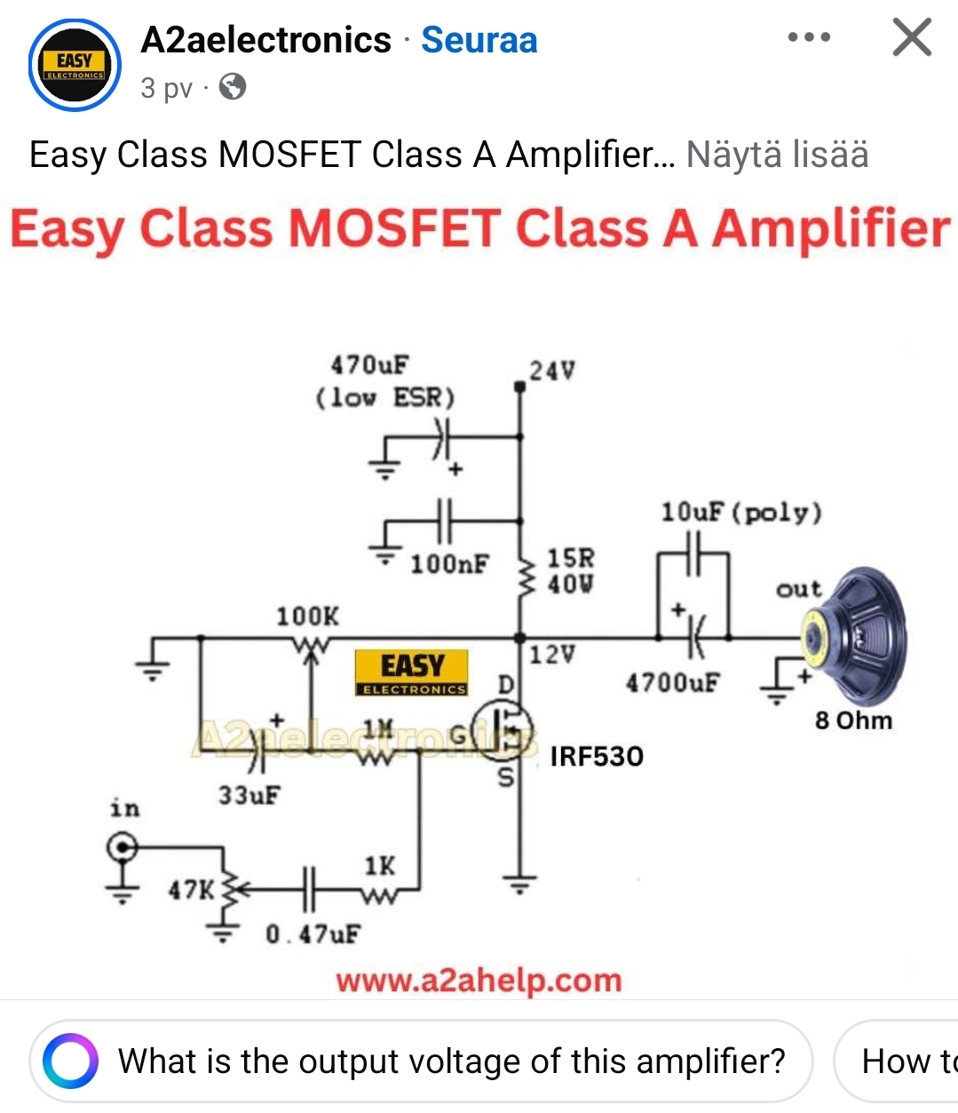
This is a classic “minimalist” single-ended Class A MOSFET amplifier. While it is praised for simplicity, it is inherently inefficient and prone to significant distortion.
In this design, the MOSFET (IRF530) is always “on,” acting as a variable resistor that pulls current through the 15 ohms load resistor.
Circuit Analysis
Operating Class: Class A. The transistor conducts through the full 360° of the input cycle.
Bias Point: The schematic shows a 12V quiescent point at the Drain (half of the 24V supply). This is achieved by adjusting the 100k potentiometer to set the Gate voltage.
Heat Generation: This circuit is a space heater. With 12V across a 15 ohms resistor, it dissipates P = (12*12)/15 = 9.6 Watts constantly, even with no music playing.
Output Voltage: The maximum theoretical peak-to-peak output voltage is roughly 24V, but in practice, it will be less due to the MOSFET’s saturation voltage and the voltage drop across the source (if a source resistor were present).
Original source
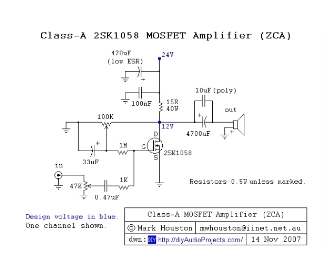
This is a single-ended Class-A common-source MOSFET stage using a 2SK1058 with a 15 Ω drain resistor and capacitor-coupled output.
I would not expect quality with this design be specifically good but maybe useable for experimenting. Class A avoids crossover distortion is true. But this simple class A design introduces other significant distortion sources.
1. Important: This design has NO global feedback
Notice:
No feedback loop from output to input
Pure resistor load at drain
Single-ended topology
That means:
Output impedance is mostly set by hardware physics
No correction via feedback
Strong interaction with speaker impedance curve
2. Realistic Output Impedance ≈ 3–7 Ω
Most likely around: ~4–6 Ω
Damping Factor Example (8Ω speaker) is 1.6
That is very low damping factor.
For comparison:
Typical Class AB: DF 50–500
Typical Class D: DF 200–1000+
What That Means Sonically
With ~5 Ω output impedance:
Bass will be loose
Frequency response will follow speaker impedance curve
Midrange may sound “rich”
Damping is minimal
This is electrically closer to a small tube amp than to a modern solid-state amp.
3. Bias & Quiescent Current
Drain resistor = 15 Ω
Supply = 24 V
Drain biased at 12 V
Current 0.8A
Maximum Output Voltage Swing
Because this is single-ended Class A with resistor load:
Max upward swing ≈ +12 V (until drain hits 24 V)
Max downward swing ≈ −12 V (until near 0 V)
Realistically subtract MOSFET saturation (~2 V), so usable peak swing ≈ ±10 V
RMS voltage: around 7V
Realistically: 5–6 W clean max for 8 ohms speaker
Efficiency:
That 32% is theoretical.
For resistor-loaded Class A:
Maximum theoretical efficiency = 25%
With real voltage drops and MOSFET limits:
Real-world efficiency ≈ 20–25%
The MOSFET will dissipate roughly:
~10 W at idle
~8–15 W under signal
That’s why it needs a serious heatsink.
Real Maximum Clean Power into 4 Ω ≈ 1.3 watts
Efficiency 6.8%
4. Distortion Estimate
This design:
Has no global feedback
Is single-ended
Has asymmetric transfer curve
Uses resistive load
Expected distortion at:
1W output:
~1–2% THD
Near full power (5–6W):
3–8% THD
Dominant harmonic:
Strong 2nd harmonic
Some 3rd
Very little crossover distortion (it’s pure Class A)
This is why these amps are often described as:
“Warm”
“Tube-like”
“Euphonic”
But technically:
Distortion is far higher than AB or D designs (<0.01%)
Distortion with 4 Ω
Because the load is heavier:
Clipping starts early
Distortion rises quickly
At 1W expect ~3–5% THD
Near max (1.3W) distortion >5–10%
It will sound:
Softer
Compressed
Less controlled bass
Very low damping factor (~4Ω / ~5Ω ≈ 0.8)
This amplifier is designed for 8 Ω or higher speakers.
Driving 4 Ω:
Wastes power
Increases distortion
Severely limits output
In this amplifier the 4700 µF output capacitor is not neutral. The 4700 µF capacitor blocks DC, passes AC to the speaker and forms a high-pass filter with the speaker. It directly affects distortion, especially at low frequencies.
How It Causes Distortion
A) Capacitor Voltage Swing Effect (Major)
Electrolytic capacitors are voltage-dependent devices.
In this amp:
The cap has ~12 V DC bias across it
Audio signal adds AC swing
So instantaneous voltage varies between ~2 V and ~22 V at high output
Electrolytic capacitance changes slightly with voltage.
That causes:
Capacitance modulation
Nonlinear impedance
Added low-frequency harmonic distortion
This increases as:
Frequency decreases
Signal amplitude increases
Load impedance decreases (4 Ω worse than 8 Ω)
B) ESR (Equivalent Series Resistance)
The capacitor has small series resistance.
At high current peaks:
Voltage drop across ESR occurs
That drop is nonlinear with temperature and ripple current
Adds small distortion
Usually minor compared to mechanism A.
C) Dielectric Absorption
Electrolytics “store memory” of previous charge.
This causes:
Slight waveform asymmetry
Mostly low-frequency distortion
Small, but measurable.
How Big Is the Effect?
For 4700 µF good-quality low-ESR electrolytic:
At 1 kHz:
Distortion from cap ≈ negligible
At 50 Hz near full power:
Can add 0.2–1% THD
At 20 Hz:
Can exceed 1–2% THD
With 4 Ω load:
Roughly doubles
And remember:
Your amp already has 1–3% intrinsic distortion.
So the cap can be a significant contributor at bass frequencies.
Why Designers Add the 10µF Poly Cap in some designa.
When you have a 10µF film cap in paraller, this:
Reduces high-frequency impedance
Bypasses electrolytic ESR at mid/high frequencies
Improves HF linearity
But it does nothing for low-frequency distortion, because 10µF is too small to affect bass.
Audible Effects
Capacitor coupling often produces:
Slight bass softening
Reduced damping
Warm character
Slight compression at high bass levels
Some people like it. Technically, it is added distortion.
Final Answer
In this amplifier the output capacitor:
Has minimal effect above ~200 Hz
Adds measurable low-frequency distortion
Increases distortion more with 4 Ω load
Slightly reduces damping factor
Contributes to the “warm” character
About 75% (est) of the power just becomes heat.
Comparison to Direct-Coupled AB Amplifier with +- power supply: A DC-coupled Class AB amp:
Has no output capacitor
Lower output impedance
Much lower LF distortion
Better bass control
That’s why modern designs avoid large output electrolytics.
Improvements ideas:
Ways to Reduce Distortion
The primary cause of distortion here is the non-linearity of the MOSFET’s transconductance and the lack of negative feedback. Here is how to clean it up:
1. Add a Source Resistor (Local Feedback)
Currently, the Source (S) is tied directly to ground. Adding a small resistor (e.g., 0.47 \Omega to 1 \Omega) between the Source and Ground introduces Degeneration.
Effect: It sacrifices some gain but makes the circuit much more linear and thermally stable.
2. Replace the Load Resistor with a Constant Current Source (CCS)
The 15 \Omega resistor is a “passive” load. As the output voltage swings, the current through the resistor changes, which causes harmonic distortion.
Effect: Replacing the 15 \Omega resistor with an active CCS (using another MOSFET or an LM317) ensures the IRF530 sees a constant current, significantly flattening the distortion curve and improving bass response.
3. Implement Global Negative Feedback
The current design has no loop to “correct” the output against the input.
Effect: You can take a portion of the output signal (before the output capacitor) and feed it back to an earlier gain stage or the gate biasing network. This “zeros out” the difference between what the input wants and what the output is actually doing.
4. Use a Better MOSFET
The IRF530 is a switching MOSFET designed for ON/OFF operations, not linear audio. Its input capacitance (C_{iss}) is non-linear.
Effect: Switching to a lateral MOSFET specifically designed for audio (like those from Exicon) or a more linear power MOSFET will reduce high-frequency harshness.
5. Improve Power Supply Filtering
Class A amplifiers have a Power Supply Rejection Ratio (PSRR) of nearly zero. Any ripple from your 24V power supply will hum directly through your speakers.
Effect: Use a regulated power supply or a “Capacitance Multiplier” circuit to ensure the DC rail is perfectly smooth.
Safety Note
The 15R 40W resistor and the IRF530 will get extremely hot. Ensure both are mounted to substantial heatsinks with thermal paste, or they will fail within minutes.
0 Comments
Be the first to post a comment.