A high voltage probe allows an ordinary voltmeter to measure voltages that would otherwise be too high to measure or even destructive. Typically normal multimeters are typically designed to measure voltage up to hundreds of volts or one kilovolt. If you need to measure higher voltage, you need to use a high voltage probe. A high voltage probe makes the measurement possible with a normal multimeter by reducing the input voltage to a safe, measurable level with a precision voltage divider circuit within the probe body.
Probes intended for up to 100 kV typically employ a resistor voltage divider, with an input resistance of hundreds or thousands of megohms to minimize circuit loading. Even higher AC voltages can be measured with capacitor divider probes.
DMM High Voltage Probe Review – What You Need To Know
https://www.youtube.com/watch?v=zyQvSCJ4q-U
Quick Tips #6 : Measuring High Voltages
https://www.youtube.com/watch?v=q7P47QDGMo8
I got my hands on an old high voltage probe: 80K-6 Suurjännitemittapää 6 kV is a high voltage probe that allows a multimeter to measure up to 6000V. Intended for low energy applications only.
The manual says:
Description
The 80K-6 is a high voltage probe designed to extend the voltage
measuring capability of an ac/dc voltmeter to 6000 volts peak AC
or DC Overvoltage Category I. This means the probe can only be
used to make measurements on energy limited circuits within
equipment. Examples include high voltage within televisions or
photo copy machines. DO NOT use this probe to measure high
voltages on power distribution systems. A 1000:1 voltage divider
provides the probe with a high input impedance. The divider also
provides high accuracy when used with a voltmeter having a 10
megohm input impedance. A molded plastic body houses the
divider and protects the user from the voltage being measured.
Specifications
The 80K-6 will achieve rated accuracy when it is used with an
ac/dc voltmeter having 0.25% accuracy, or better, and an input
impedance of 10 megohms ±10%. Specifications for the probe
are as follows:
Voltage Range: 0 to 6 kV, dc or peak ac
Input Impedance: 75 megohms nominal
Division Ratio: 1000:1
Accuracy:
DC to 500 Hz: ±1%
500 Hz to 1 kHz: ±2%
Above 1 kHz: Output reading falIs.
Typically, -30% at 10 kHz.Safety:
CAN/CSA C22.2 No. 1010.2.031-94 & IEC 1010-2-031:1993,
Type B, 6 kVDC or peak AC, 4.24 kV rms AC, Overvoltage
Cat. I (Voltage derived from limited energy transformers).
More information: Fluke 80K-6 user manual
Here are some video of the “bigger brother” of that probe:
High Voltage Probe How-to with Fluke 80K-40
https://www.youtube.com/watch?v=kXq4FCQ0C38&t=27s
FLUKE 80K – 40 HV Probe ( Who Remember This Tool )
https://www.youtube.com/watch?v=1aYLGC8VcNs
Let’s dig in how this probe is built:
From manual:
The 80K-6 is compatible with any ac or dc voltmeter that has an
input impedance of 10 megohms ±10%. Voltmeters with higher
input impedances require the use of an external shunt to obtain
an accurate measurement.
The 80K-6 represents a load of approximately 75 megohms to the
circuit being measured (13 µA per 1 kV).
The manual Figure 1 shows the circuit diagram of this probe:
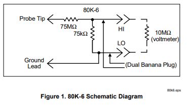
The manual says that to get the whole probe accurate resistance, measure the resistance of of the 80K-6 at its voltmeter connector and multiply the measured value by 1000. The output resistance of the probe to the multimeter is around 77 kohms on the probe I had.
The probe needs to be built accurately and have good accuracy. High linearity and accuracy is achieved by using resistors with extremely low voltage coefficients. The manual says about accuracy and calibration:
Verify the probe accuracy by measuring a 5 kV dc ±0.25% voltage
source. When used with a compatible dc voltmeter, the probe
should accurately measure the source voltage to within ±1%. No
calibration adjustments are provided on the probe.
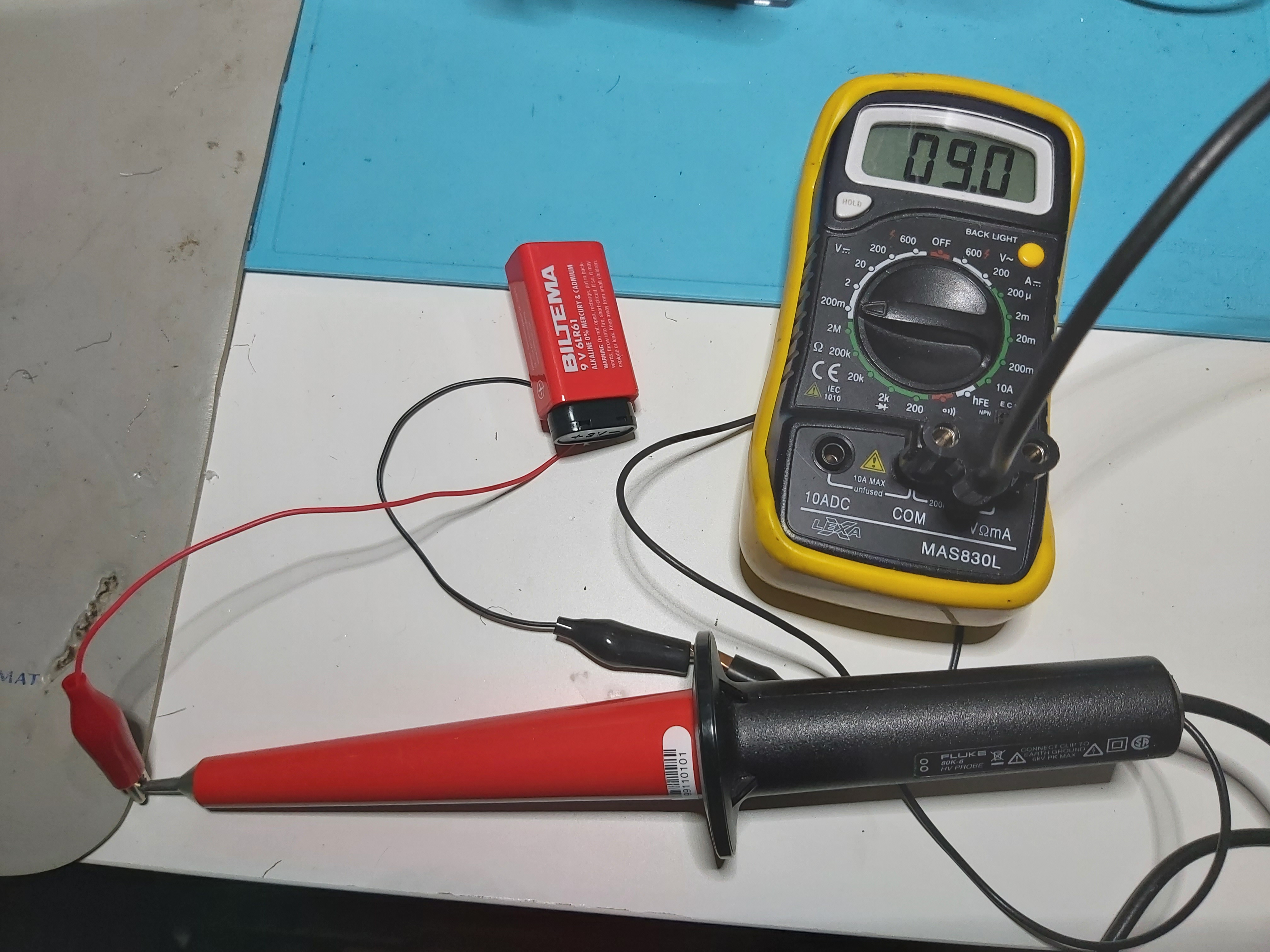
In my tests I did not have access to 5 kV DC source, so I had to do my verification using other means. What I had was 9V battery and also adjustable DC source that can be adjusted up to 2.7 kV.
Then using this type high voltage probe, the voltmeters have input resistance that effectively alters the probe’s divider ratio. If the multimeter input impedance is 10 megaohms ±10%, the DC reading will be altered less than ±1%. When measuring AC signals, the parasitic capacitance that combines with the probe’s resistance to form an RC circuit; these can easily reduce AC accuracy. This is why Fluke recommends staying below 500 Hz signals to get decent accuracy.
The manual gives the following help for those who need to do repairs (I had to do that because of damaged wires):
Disassembly
Use the following procedure to disassemble the probe:
1. Unscrew the black handle from the probe, and slide the
handle onto the cable.
2. Unscrew the metal tip one turn, and push in on the tip until
the internal assembly snaps free of the housing. Remove the
tip.
3. Withdraw the internal assembly from the probe by pulling the
metal ring over the threads on the probe body.
4. Logically reverse this procedure to reassemble the probe.
The high voltage problem I got my hand to was old. But some Googling shows that this probe is still available from various sources:
ELFA Distrec sells 80K-6 – Korkeajännitemittapää 6 kV yleismittariin, 248mm, Neula, Musta, punainen, Fluke for EUR 302,56 with taxes.
RS Components sells Fluke Test Probe for € 302,56.
kpl (Sis ALV:n)
There seems to same type of probes in eBay for sale for around 60 EUR price range (are they new, used or counterfeit hard to say). The probes for sale can be found here and here.
What if you want to DIY your own high-voltage 1:1000 probe. There seems to be web pages with DIY ideas for high voltage probes. Here are some links:
https://www.instructables.com/DIY-HIGH-VOLTAGE-MULTIMETER-PROBE/
https://www.youtube.com/watch?v=8m6HcwPwhw8
https://www.youtube.com/watch?v=Rl8I4PO66Uw
https://www.youtube.com/watch?v=RAOw0mHQRvk
If you build and use this probe, you do so at your own risk! High voltage can seriously hurt you and damage your equipment! Properly rated high voltage components are not easy to get and construction needs to be done right and carefully.
6 Comments
McDVOICE says:
Thanks for the information. Keep it up.
kdealer login says:
Thanks for reaching out. We’d love to help you out here. Hence, we kindly request you to provide a brief summary of the issue you are facing. Thanks so much and let us know if you have any other concerns.
Felix says:
WoW !!!! What a detailed analysis
fnaf says:
Let’s dig in how this probe is built
Tomi Engdahl says:
https://hackaday.com/2024/03/14/high-voltage-fun-with-an-inexpensive-power-supply/
https://baltic-lab.com/2024/03/inexpensive-5-kv-to-30-kv-high-voltage-power-supply/
Tomi Engdahl says:
I found this. Someone commented with a link to Big Clive’s 6 year old video of this sealed HVDC module, but he didn’t show its guts. So here’s a link to a video of the internals laid out.
Inside a 400 kV high voltage module ( epoxy removal, testing , circuit diagram, simulation )
https://m.youtube.com/watch?v=mTx8pMHo4jI&si=WW9w765DMXAmD2Np&fbclid=IwAR3UlpxrNt-uSrBJ5Ikk6iKRZ7zD3tVUzFPs1IpuBHh2kyCDRfmezjov3IM