I saw this circuit design at “I take pictures of electronics part @Facebook”
https://m.facebook.com/groups/ElectronicParts/permalink/2237548103101179/
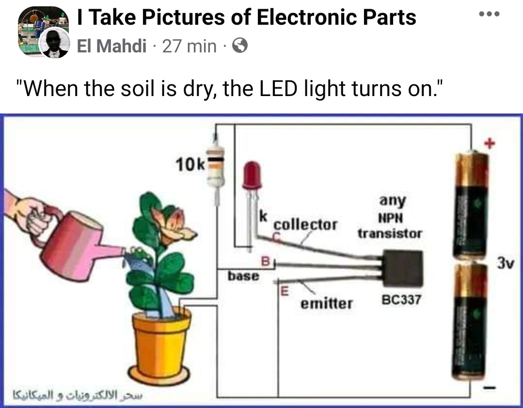
As many circuit designs posted to Facebook, this has it’s problems and non-idealities. Here are some comments on this circuit design:
1. At worst case LED will shine bright as a star in the sky until either it or the transistor burns out. There should be a current limiting resistor in series with the LED. You can add a resistor in series with LED or in transistor emitter lead. The discussion claims that 180 ohms should be about right.
2. There is some DC (max 0.3 mA) floating all the time throughout sensor wires will corrode many metals sooner or later so that they will no longer work well. If you use copper wires, they will leak copper ions to the flower pot and enough of them in pot can kill your flowers. Some people have recommended to use carbon electrodes to avoid corrosion (rods scavenged out of old fashioned dry cells as electrode? Do they have harmful battery chemicals).
If you want to build a better moisture sensing circuit, try capacitive humidity sensors. The best sensors are capacitive. No physical contact with the humidity, no corrosion. I suggest measuring soil moisture by measuring electrical capacity, not conductivity. Here is a video on capacitive moisture sensors: https://youtu.be/pFQaFnqpOtQ
4 Comments
Maria says:
The cautionary note about the presence of DC current and its potential to corrode metals, leading to ineffective sensors or even harmful effects on plants, underscores your awareness of the practical implications of sensor design. Your suggestion of using carbon electrodes as an alternative to copper is thoughtful and shows consideration for the health of the plants.
Tomi Engdahl says:
SOIL MOISTURE SENSOR FOR PLANTS (V1.2 / V2.0) – Arduino tutorial #31
https://www.youtube.com/watch?v=pFQaFnqpOtQ
The capacitive soil moisture sensor allows you to measure the moistness of soil. The biggest advantage over a traditional moisture sensor is that the capacitive sensor doesn’t corrode. In this tutorial I’ll explain how you can read the soil moisture sensor and what the advantages are. Further you learn how to work with the map() function and how to calculate the soil moisture in percentage.
Many ask what the difference is between v1.2 and v2.0, this is what I found:
- The spelling of the out pin: AOUT on v1.2 and AUOT on the v2.0
- The top of the PCB shows a tiny circle on v2.0
Capacitive Soil Moisture Sensors don’t work correctly + Fix for v2.0 v1.2 Arduino ESP32 Raspberry Pi
https://www.youtube.com/watch?v=IGP38bz-K48
In this episode I talk about capacitive soil moisture sensors and why 82% of them dont work correctly. I analyze the 3 most common problems they have by design and show you how to fix them or how to find sensors that work right away.
You can jump to one of these sections:
0:00 Introduction
0:39 Flaura – the smart, self-watering plant pot
1:20 Resistive sensors suck
2:03 Working principle
2:43 Learnings from 38 orders
3:47 Missing voltage regulator
5:11 Wrong timer chip
6:57 Missing resistor connection
9:39 Fixes
10:01 Ordering advices
Tomi Engdahl says:
Why most Arduino Soil Moisture Sensors suck (incl. solution)
https://www.youtube.com/watch?v=m0mcCtcViTY
Unfortunately, most soil moisture sensors used in our Arduino, ESP8266, or ESP32 projects destroy themselves after a short while. We need a better solution.
Today we will test different sensors, and I will show you how they work and why most sensors from China destroy themselves. And, of course, we will find a solution to the problem.
#207 Why most Arduino Soil Moisture Sensors suck (incl. solution)
https://www.youtube.com/watch?v=udmJyncDvw0
Tomi Engdahl says:
https://hackaday.io/project/191963-completely-analog-houseplant-soil-moisture-sensor