I wrote around two years ago a blog posting on RJ-45 Ethernet surge protection. Now it is time to check out what is inside one cheap Ethernet surge protector. The product here is very cheap (around $2) CY UT-013 Lightning Protection RJ45 UTP STP CAT6 CAT5e Female to Female Network Lan Adapter Extender. The specifications promised on the product page are:
RJ45 UTP STP CAT6 CAT5e Female to Female Network Lan Adapter Extender
With Lightning Protection & Shield
Used to connect two RJ45 cables together
Make two RJ45 cables work as one cable
Straight through configuration
8 Conductors w/ Gold-plated contacts
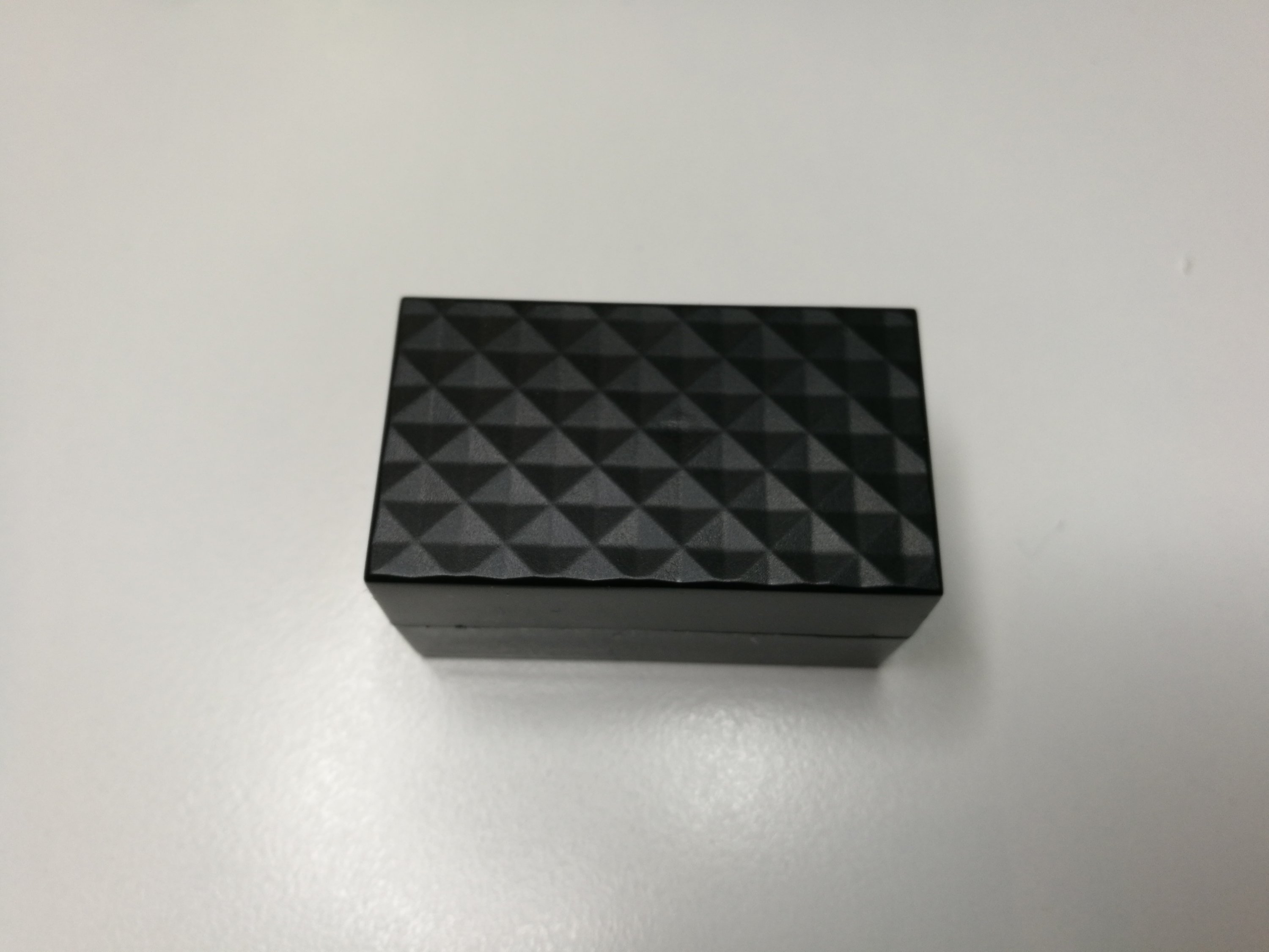
This seems to be a product that would work for general Ethernet over-voltage protection. The general construction looks OK:
Let’s take a look inside. It was pretty easy to open with some force because the case just seems to be hot-glued together.
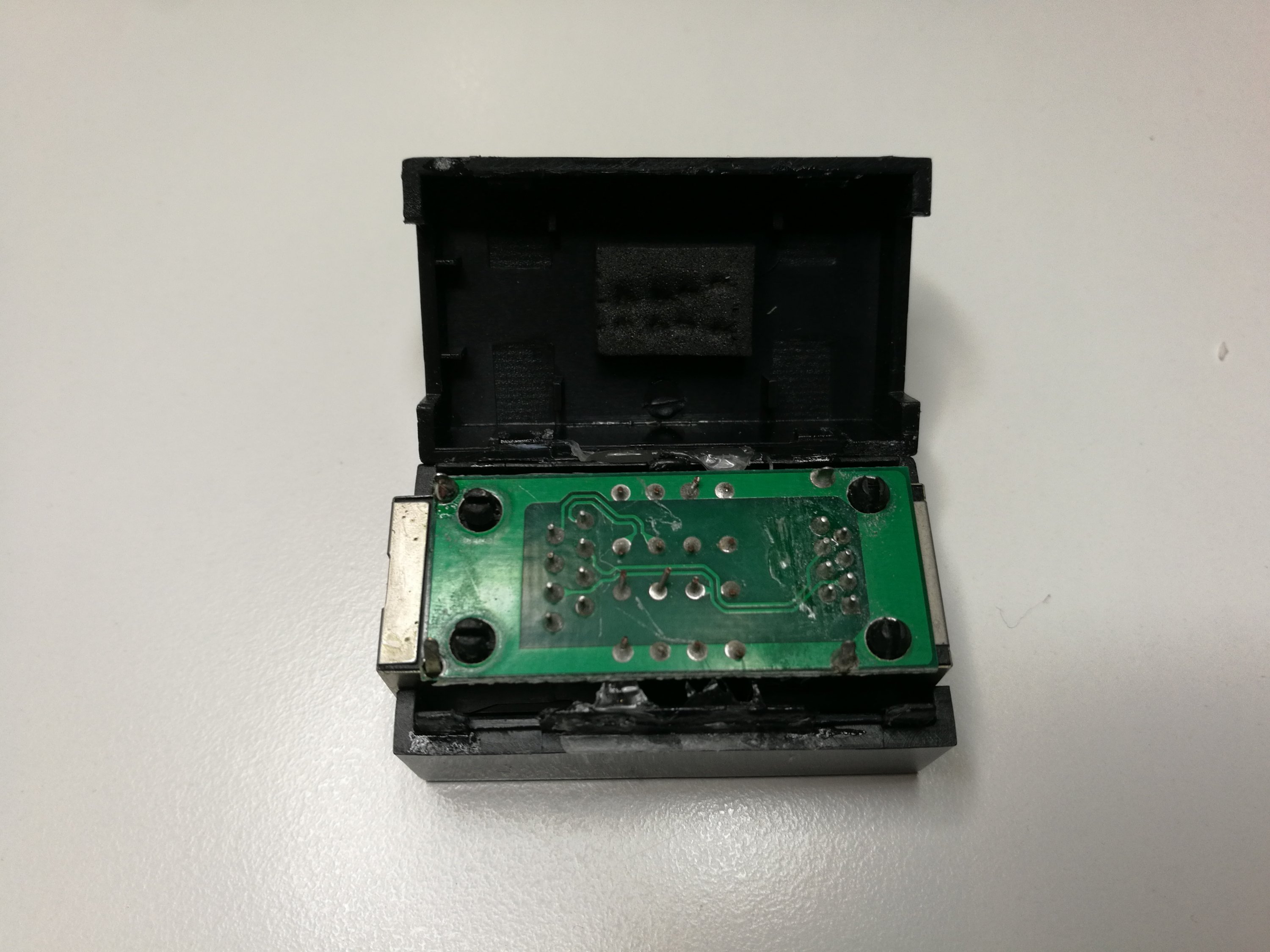
There seems to be eight small signal protection components components here. Those protective components are wired all between signal wire and the ground that is on the RJ-45 connector shield. This kind of protection device needs to be wired to a well grounded shielded (STP) network wiring to work best. If it is connected to UTP wiring, the protection level it provides is very much limited. There is no connection for any separate ground.
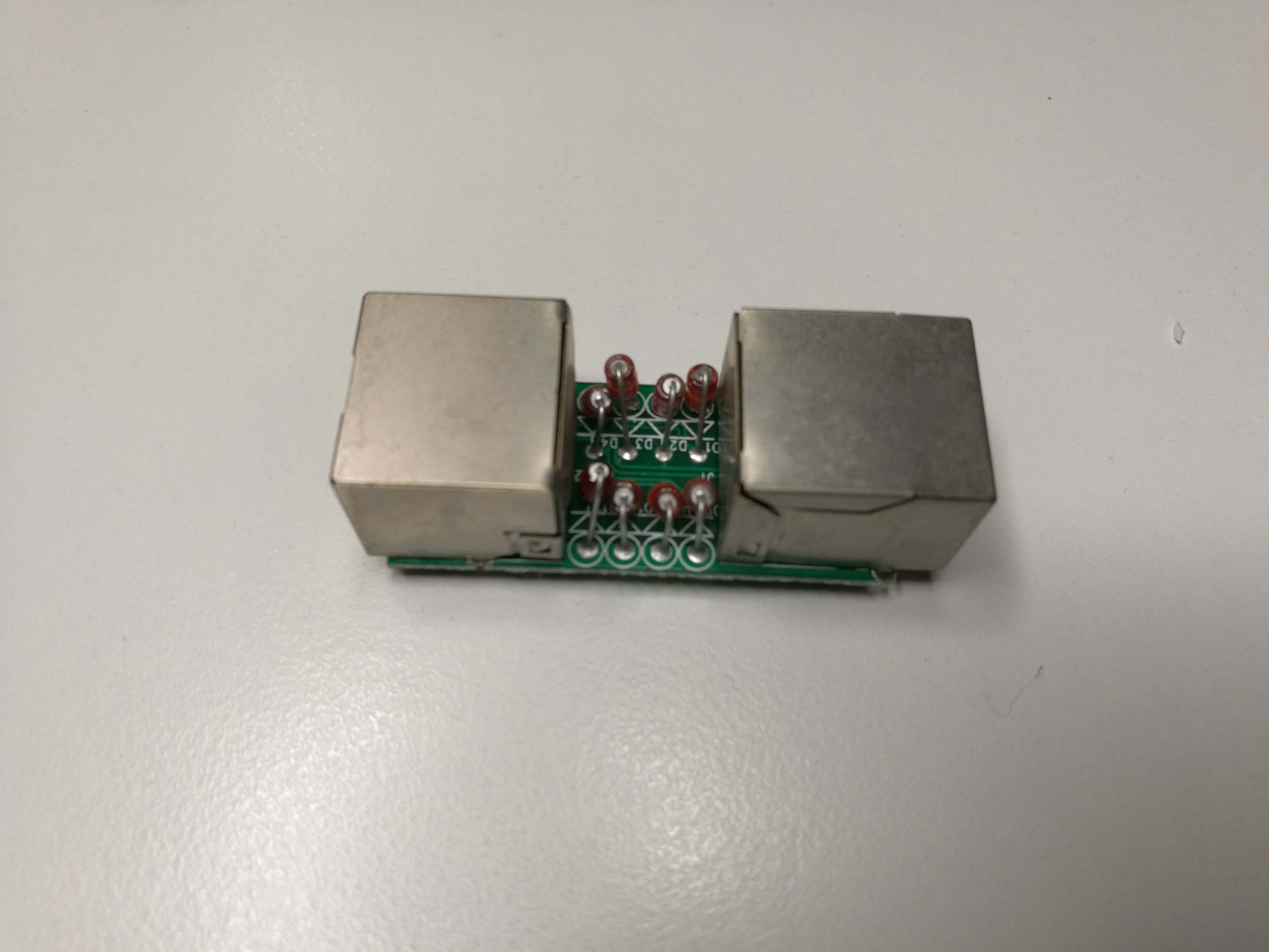
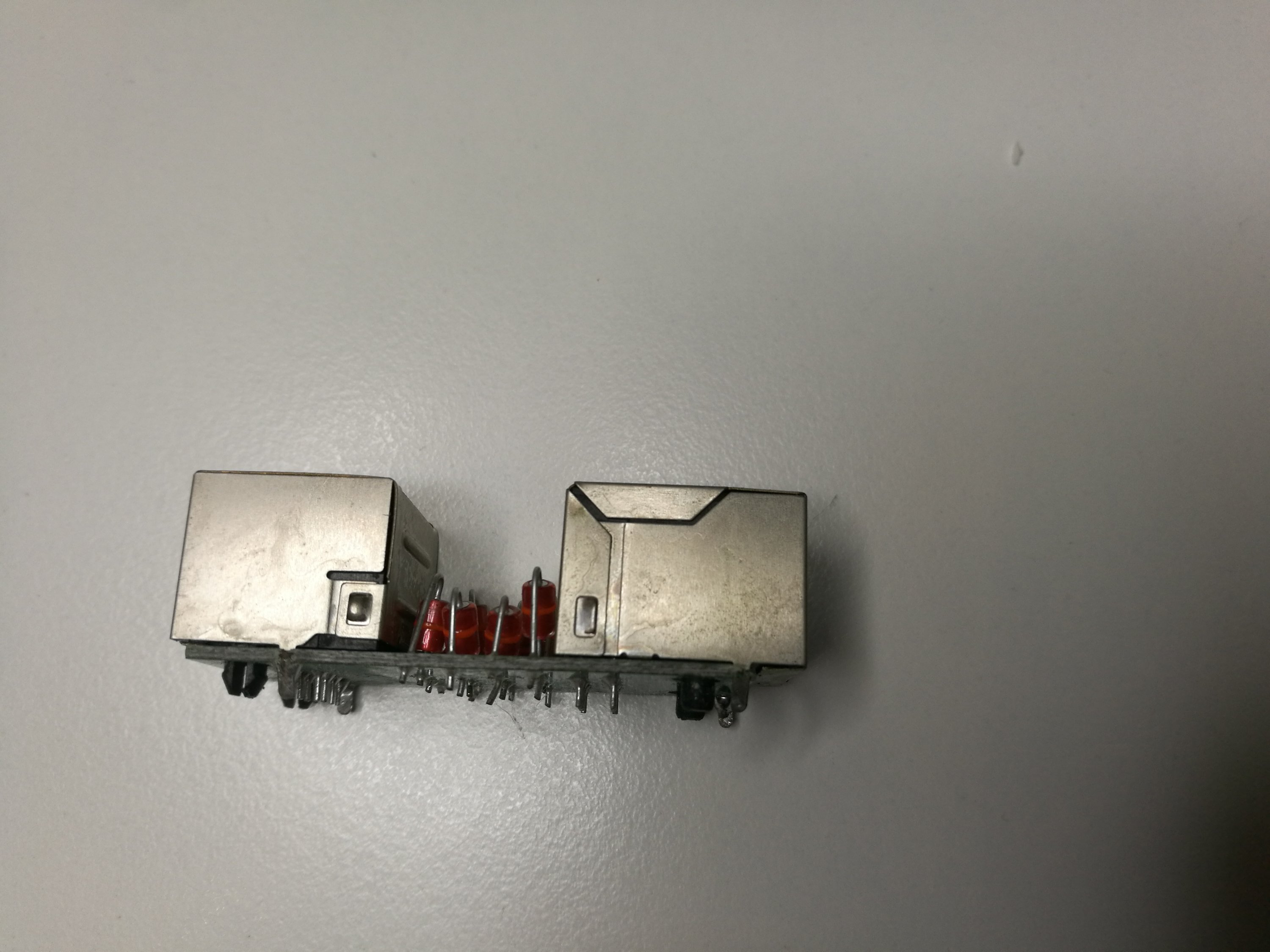
The general construction of the device looks OK. The wiring on board looks decent as different pairs are nicely routed as pairs on the board. If the capacitance is low and the operation voltage of those protection devices this construction looks basically OK.
The question remains what type of components they are and at what voltage they operate. They do not seem to have any readable markings.
I did few measurements:
The capacitance on those protection devices looks very low. I had hard time to do reliable measurement of them while they are in the circuit (and decided not to remove them), so I don’t have very accurate numbers here. The capacitance looks to be in order of few pF or so. I would say that very low and I don’t thinks would have serious effect on Ethernet signals.
Then I tried to measure the voltage they operate. For that I used an insulation resistance meter (250/500/1000V test voltage ranges) and a multimeter.When I did insulation resistance test 250V DC I got open circuit reading. It’s good that they can handle some DC, so they do not start to conduct at voltage used by for example Power over Ethernet (48-56V DC). Ethernet cards are designed to handle more than 250V voltage (typically designed for 1500V isolation level).
When I did the insulation resistance test at 500D DC voltage, I started to see some flashing on the protection component. When I measured the voltage that is left over the protection device when insulation resistance tester tries to feed 500 V DC at quite low current, I got reading that was at around 150V DC.
The end result seems to be that protection component seems to be miniature gas discharge tube from pin to shield. This type of protection components have typically very small capacitance, quite fast operation and can handle reasonable surges well. This Alibaba page seems to have somewhat similar looking (ruilon RLM501-141M) 500A miniature gas discharge tubes (8/20us,1time) for sale – they promise very small electrostatic capacitance(<0.8pF) and great isolation(>100MΩ) and available at several voltages from 140V to 700V.
This was a quick look what is inside. To really see how effective those are more tests would be needed to be performed with suitable surge voltage source.
1 Comment
Richard says:
Possible the components are diacs. Probably cheap standard ones at that. 240v working ? Turn on at 150v sounds about right.