I saw this circuit seen on Facebook at https://www.facebook.com/share/r/1GAqZQWc7y/
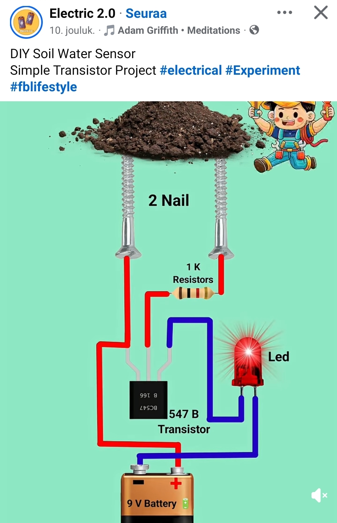
In this circuit design the soil acts as a simple moisture sensor by changing electrical resistance with water content, forming a basic circuit with two probes (wires) connected to transistor and indicator LED.
Water conducts electricity better than dry soil. When water fills the gaps between probes, it completes a circuit, lowering resistance.
This looks somewhat better than average AI slop circuits (that Facebook is now filled with nowadays), just two mistakes:
1. The pinout of transistor is wrong. Here is the correct pinout.

2. There is no current limiting resistor for LED – if the sensors touch each other or there is low resistance (like salty water) the LED and transistor will be fried. At favorable conditions the circuit (ground water conducts enough not too much) the circuit might work.
One additional commend:
This circuit design not suitable for long time use, the sensor screws will rust due DC current flowing through them. Constant voltage and constant current flowing accelerates metal corrosion, which changes readings. You’ll slowly dissolve whichever metal you use into the soil, so steel and copper may corrode and others may form other salts. Some of the metal from those processes could be potentially somewhat toxic when it ends to the soil. For example stainless steel can leach chromium into the soil which is quite toxic. Copper in high concentrations is not also good.
2 Comments
cznsavedata says:
Great catch on that transistor pinout! It’s refreshing to see someone actually auditing circuit diagrams instead of just scrolling past AI-generated content. Precision in hardware is just as critical as precision in software data management. In my own projects, especially when managing complex gaming systems, I have to be just as meticulous with the Zero System’s limits. I use the https://www.cznsavedata.com/ calculator to ensure my data parameters are exact, otherwise, the auto-pruning kicks in and ruins the whole ‘circuit.’ Thanks for keeping the technical standards high!
kdealer plus says:
This soil moisture circuit has practical issues: missing current-limiting resistor and incorrect transistor pinout can damage components. kdealer plus