I saw this viral circuit in Facebook https://www.facebook.com/share/p/1EEBkqkNr3/

It is a working concept but bad viral implementation: That 100 ohm resistor will heat up and consume the battery quite quickly. The 100 ohms resistor is so low value that it can potentially damage the transistor because maximum allowed transistor base current is exceeded when alarm is activated (detection wire is cut).
Here is a video of one alarm build with more sensible resistor value:
Here is another design from
https://www.facebook.com/groups/electricaltechnicaltips/posts/1299510351762337/
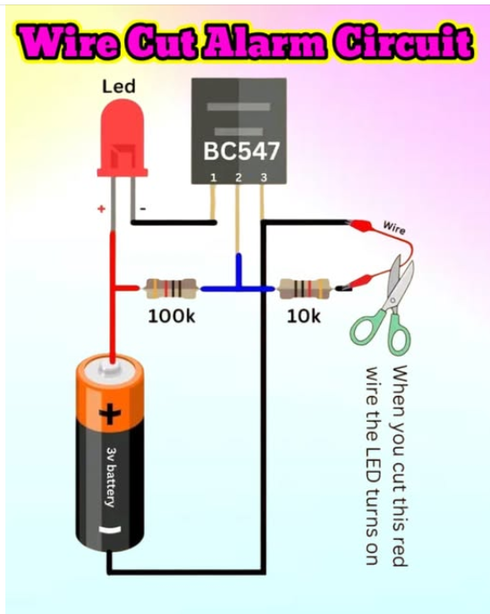
This is a simple **Wire Cut Alarm Circuit** designed to detect when a wire is cut. It uses a **BC547 NPN transistor**, an **LED**, resistors, and a **3V battery**. The red wire connected through a 10kΩ resistor to the transistor’s base acts as a trigger. As long as the wire remains intact, the transistor stays off and the LED remains off. If the wire is **cut**, the base of the transistor no longer receives voltage, causing the transistor to **turn on**, which in turn **activates the LED**, serving as an alarm. This type of circuit can be used in basic security systems to alert when a connection has been tampered with.
This is a classic transistor-based “normally closed” (NC) alarm circuit. It uses a BC547 NPN transistor as an electronic switch to monitor the state of a physical wire.
1. Key Components
BC547 Transistor: The “brain” of the circuit. It acts like a gate that only allows power to flow through the LED if it receives a small voltage at its Base (Pin 2).
100kΩ Resistor: Acts as a “pull-up” resistor, trying to turn the transistor ON.
10kΩ Resistor & Wire: Act as a “pull-down” path, keeping the transistor OFF while the wire is intact.
2. How it Works (The Logic)
State A: The Wire is Intact (Alarm Silent)
When the red wire is connected, it creates a path to the negative terminal (ground).
The two resistors (100kΩ and 10kΩ) form a voltage divider.
Because the 10kΩ resistor is much “weaker” (lower resistance) than the 100kΩ resistor, it pulls the voltage at the Base (Pin 2) down very close to 0V.
An NPN transistor needs about 0.7V at its base to turn on. Since the voltage here is roughly 0.27V, the transistor stays OFF, and the LED remains dark.
State B: The Wire is Cut (Alarm Active)
When you cut the wire, the path to the negative terminal is broken.
The 10kΩ resistor is now “disconnected” from the ground.
The 100kΩ resistor is now free to “pull” the Base voltage up toward the full 3V of the battery.
The transistor turns ON (enters saturation), allowing current to flow from the Collector (Pin 1) to the Emitter (Pin 3).
This completes the circuit for the LED, and it lights up.
LED Protection: The diagram doesn’t show a current-limiting resistor for the LED. Depending on the transistor properties (current amplification factor that vary in 110 – 800 for BC547 transistor) there might or might not be current limiting for LED. While a 3V battery might not immediately blow a standard red LED (which usually handles ≈2V), it’s best practice to put a small resistor (like 100Ω) in series with the LED to prevent it from burning out over time.
Sensitivity: Using a 100kΩ resistor means the “trigger” current is very low, making the circuit very power-efficient while in “monitoring” mode.
Related links:
Wire Break Alarm Circuit With IRFZ44N MOSFET
https://www.instructables.com/Wire-Break-Alarm-Circuit-With-IRFZ44N-MOSFET/
How can I make an alarm circuit which senses both cutting and shorting the wire?
https://electronics.stackexchange.com/questions/699628/how-can-i-make-an-alarm-circuit-which-senses-both-cutting-and-shorting-the-wire
0 Comments
Be the first to post a comment.