Software-defined radio (SDR) is a radio communication system where components that have been traditionally implemented in hardware (e.g. mixers, filters, amplifiers, modulators/demodulators, detectors, etc.) are instead implemented by means of software on a personal computer or embedded system.
Experimenting with software defined radio used to be expensive, but now it is cheap. Nowadays it is very cheap to start experimenting with SDR. Most receivers use a variable-frequency oscillator, mixer, and filter to tune the desired signal to a common intermediate frequency or baseband, where it is then sampled by the analog-to-digital converter. Cheapest wide receiving range well working device is to use suitable DVB-T receiver stick (10-20 Euros/Dollars) and suitable software (very many alternatives, for example SDRsharp and Gnu Radio).
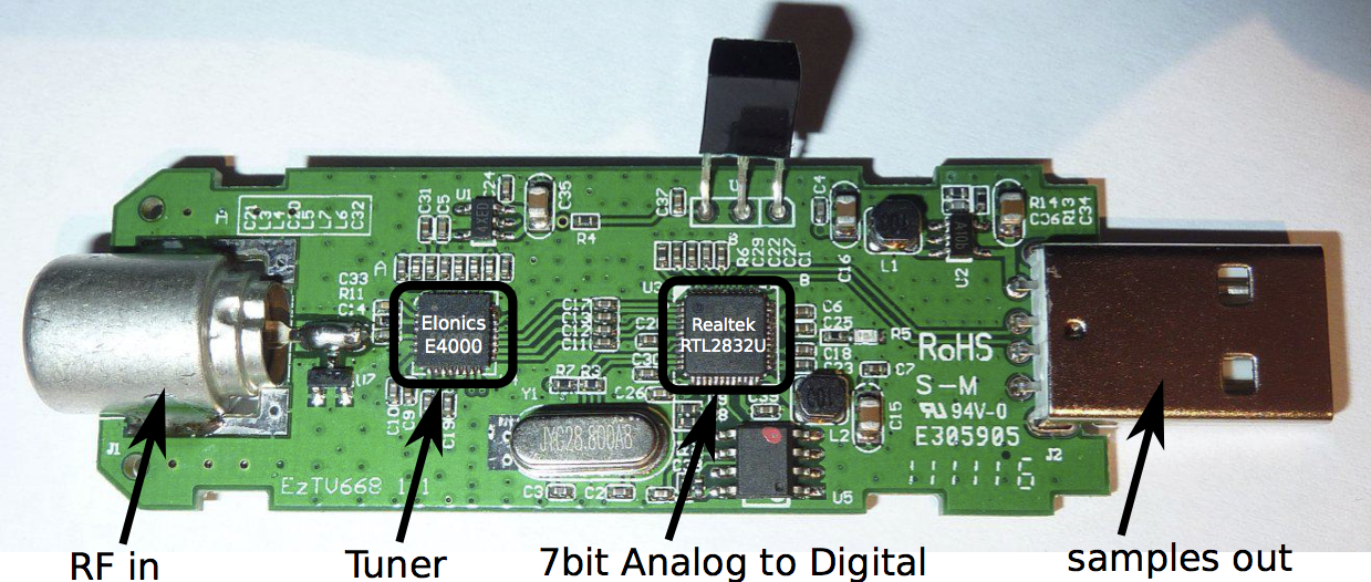
My article Software defined radio with USB DVB-T stick started the long list of SDR related postings. The newest postings now are Filter measurements with RF noise source and Antenna measurements with RF noise source.
432 Comments
Tomi Engdahl says:
ESP8266 Adds WiFi To A 433 MHz Weather Station
https://hackaday.com/2021/05/26/esp8266-adds-wifi-to-a-433-mhz-weather-station/
Tomi Engdahl says:
https://circuitdiagrams.in/wave-propagation/
Tomi Engdahl says:
HF SDR Transceiver RS-918 mcHF
https://www.youtube.com/watch?v=YC4mlC5_U-4
Here we take a look at the RS-918 HF SDR Transceiver, a typical clone of the mcHF.
mcHF QRP transceiver
http://www.m0nka.co.uk/
Tomi Engdahl says:
How To Run A First-Generation Cell Phone Network
https://hackaday.com/2021/06/02/how-to-run-a-first-generation-cell-phone-network/
Retro tech is cool. Retro tech that works is even cooler. When we can see technology working, hold it in our hand, and use it as though we’ve been transported back in time; that’s when we feel truly connected to history. To help others create small time anomalies of their own, [Dmitrii Eliuseev] put together a quick how-to for creating your own Advanced Mobile Phone System (AMPS) network which can bring some of the classic cellular heroes of yesterday back to life.
Few readers will be surprised to learn that this project is built on software defined radio (SDR) and the Osmocom-Analog project, which we’ve seen before used to create a more modern GSM network at EMF Camp. Past projects were based on LimeSDR, but here we see that USRP is just as easily supported.
HowTo: Running the 1G Analog Phone from 1997
https://medium.com/geekculture/howto-running-the-1g-analog-phone-from-1997-3caec77a9df9
Tomi Engdahl says:
https://hackaday.com/2021/05/18/send-old-fashioned-pager-messages-with-new-fashioned-hardware/
Tomi Engdahl says:
Building a crystal radio set
Updated Friday, 30th August 2019
https://www.open.edu/openlearn/science-maths-technology/science/physics-and-astronomy/physics/building-crystal-radio-set
For many of the original teenagers, home-built crystal radios gave them their first contact with the world beyond their bedrooms. Here, Fraser Robertson describes how to make your own.
Tomi Engdahl says:
Raspberry Pi Hat Adds SDR With High Speed Memory Access
https://hackaday.com/2021/06/20/raspberry-pi-hat-adds-sdr-with-high-speed-memory-access/
An SDR add-on for the Raspberry Pi isn’t a new idea, but the open source cariboulite project looks like a great entry into the field. Even if you aren’t interested in radio, you might find the project’s use of a special high-bandwidth memory interface to the Pi interesting.
https://github.com/cariboulabs/cariboulite
CaribouLite is an affordable, educational, open-source SDR platform that is also a HAT for the Raspberry-Pi family of boards (40-pin versions only). It is built for makers, hackers, and researchers and was designed to complement the SDR current eco-systems offering with a scalable, standalone dual-channel software-defined radio.
Unlike many other HAT projects, CaribouLite utilizes the SMI (Secondary Memory Interface) present on all the 40-pin RPI versions. This interface is not thoroughly documented by both Raspberry-Pi documentation and Broadcomm’s reference manuals. An amazing work done by Lean2 (code in git repo) in hacking this interface contributes to CaribouLite’s technical feasibility. A deeper overview of the interface is provided by G.J. Van Loo, 2017 Secondary_Memory_Interface.pdf. The SMI interface allows exchanging up to ~500Mbit/s between the RPI and the HAT, and yet, the results vary between the different versions of RPI. The results further depend on the specific RPI version’s DMA speeds.
In our application, each ADC sample contains 13 bit (I) and 13 bit (Q), that are streamed with a maximal sample rate of 4 MSPS from the AT86RF215 IC.
RF Channels:
Sub-1GHz: 389.5-510 MHz / 779-1020 MHz
Wide tuning channel: 30 MHz – 6 GHz (excluding 2398.5-2400 MHz and 2483.5-2485 MHz)
Tomi Engdahl says:
Elektrobit Propsim+ Radio Channel Simulator
https://www.youtube.com/watch?v=WMHOdC48LHM
Tomi Engdahl says:
Listen To The RF Around You
https://hackaday.com/2021/06/27/listen-to-the-rf-around-you/
These days, we are spoiled for choice with regard to SDRs for RF analysis, but sometimes we’re more interested in the source of RF than the contents of the transmission. For this role, [Maker_Wolf] created the RFListener, a wideband directional RF receiver that converts electromagnetic signal to audio.
The RF Listener is built around a AD8318 demodulator breakout board, which receives signals using a directional broadband (900 Mhz – 12 Ghz) PCB antenna, and outputs an analog signal. This signal is fed through a series of amplifiers and filters to create audio that can be fed to the onboard speaker. Everything is housed in a vaguely handgun shaped enclosure, with some switches on the back and a LED amplitude indicator.
https://www.wolfsprojectfiles.com/projects/rflistener.php
Tomi Engdahl says:
https://hackaday.com/2021/06/20/raspberry-pi-hat-adds-sdr-with-high-speed-memory-access/
Tomi Engdahl says:
https://hackaday.com/2021/07/11/tuning-into-medical-implants-with-the-rtl-sdr/
Tomi Engdahl says:
The lure of the ladder line
https://www.robkalmeijer.nl/techniek/electronica/radiotechniek/hambladen/qst/1993/12/page70/index.html
Tomi Engdahl says:
https://robs-blog.net/2019/07/02/100w-dummyload/
Tomi Engdahl says:
https://robs-blog.net/2018/06/17/crystal-frequency-tester/
Tomi Engdahl says:
https://hackaday.com/2021/08/06/sbitx-hackable-hf-sdr-for-the-raspberry-pi/
Tomi Engdahl says:
https://hackaday.com/2021/08/19/wheres-that-radio-a-brief-history-of-direction-finding/
Tomi Engdahl says:
The Curious Case Of The Radio Amateur And The Insulin Pump
https://hackaday.com/2021/08/29/the-curious-case-of-the-radio-amateur-and-the-insulin-pump/
A substantial part of gaining and holding an amateur radio licence relates to the prevention of radio interference. In days past this meant interference to analogue television broadcasts, but with ever more complex devices becoming commonplace in homes it applies to much more. This has hit the news in Marion County Florida, where a radio amateur in a senior’s community has shut down his radio station after a potential link emerged between it and another resident’s insulin pump. There is a legal challenge ongoing that relates to the complex’s rules over transmitting antennas.
It’s obviously a serious occurrence for an insulin pump to be affected by anything, and it sounds as though the radio amateur concerned has done the right thing. But it’s clear that something has gone badly wrong in this case whether it’s due to the amateur radio transmissions or not, because for a manufacturer to produce a medical device so easily affected by RF fields should be of concern to everyone.
Woman fights to have ham radio operations banned after potential interference with insulin pump
https://www.wftv.com/news/9investigates/woman-fights-have-ham-operations-banned-after-potential-interference-with-insulin-pump/GA5IHWEQGFA7XHLOLPQDVEZGCQ/
A Marion County woman is taking on her neighborhood association, in a matter she said puts her health at risk.
Michelle Smith, a Type 1 Diabetic, and a consultant determined that her neighbor’s ham radio hobby might have interfered with the doses of insulin being pushed out from her pump.
The 55+ community where she lives hired that consultant and told the neighbor to shut down his amateur radio station.
But a copy of the community’s rules shows a change was put in place that could pave the way for other similar antennas to be installed.
In the manicured subdivision of Indigo East near Ocala, managed by On Top Of The World, two neighbors say they’ve thought of moving away from the development’s amenities because of the ongoing dispute.
Smith has been in the back and forth with the community’s association for more than a year after noticing the insulin pump she uses to manage her Type 1 Diabetes was suddenly giving the wrong amount of the medicine that keeps her alive.
“So I switched pumps, bought another one, switched reservoirs, threw insulin away, did everything I knew of to troubleshoot,” she said.
After doing some research, she suspected the problem might be a few doors down in equipment that is now unplugged and collecting dust.
David Birge was told to shut down his ham radio operation after On Top Of The World hired an independent consultant to investigate Smith’s complaints.
That engineer determined the “amateur radio operator could have produced” radio frequency levels that exceeded those Smith’s insulin pump is intended to operate in.
“I’ve lost a hobby I’ve enjoyed more than half of my lifetime, and the equipment sitting in my office is not plugged in,” Birge said.
Though his operation was shut down for now, the community’s board of directors changed the wording in its rules and regulations to potentially allow more of these amateur radios in the future — changing the definition of antenna allowed after approval from “a device used to receive” to one that could also “transmit” radio frequency signals.
Tomi Engdahl says:
Cable Modem Turned Spectrum Analyzer
https://hackaday.com/2021/08/27/cable-modem-turned-spectrum-analyzer/
Hopefully by now most of us know better than to rent a modem from an internet service provider. Buying your own and using it is almost always an easy way to save some money, but even then these pieces of equipment won’t last forever. If you’re sitting on an older cable modem and thinking about tossing it in the garbage, there might be a way to repurpose it before it goes to the great workbench in the sky. [kc9umr] has a way of turning these devices into capable spectrum analyzers.
While it’s somewhat down to luck as to whether or not any given modem will grant access to this feature, for the ones that do it seems like a powerful and cheap tool. It’s agnostic to platform, so any computer on the network can access it easily, and compared to an RTL-SDR it has a wider range. There are some limitations, but for the price it can’t be beat which will cost under $50 in parts unless you happen to need two inputs like this analyzer .
Cable Modem Spectrum Analyzer
http://www.kc9umr.com/?p=759
Finally, I dd manage to acquire an Arris SB6183. Score. As a “user-procured” device, the cable companies couldn’t (or didn’t) push a fix into it. I connected the Ethernet cable to my Toughbook, logged in to the web interface (192.168.100.1:8080), and was instantly granted access to the spectrum analyzer function. I keyed up a nearby handheld transmitter in the VHF band (154 MHz), and saw the spectrum respond accordingly! Obviously, with no antenna connected, I expected very little in terms of performance.
Once I got home, I added couple RF adaptors, then had an SMA magnet mount scanner antenna connected to the F type connector.
Now – lets not pretend there are no Limitations. There is never a completely free lunch. The analyzer is capable, but has some limitations. Here’s the basic feature rundown that mine has-
Amplitude reporting units: dBm
Noise floor: Approximately -100 dBm
Maximum Span: 1 – 1000 MHz
Minimum Span: 6 MHz
Clear Write / Max Hold modes, with video averaging available
Max input level unknown, I would guess 0 dBm would be a safe maximum.
Input impedance: 75 ohms
Automatic marker will follow a mouse pointer over the trace
mouse click-to-drag to change center frequency on the fly
Regarding the amplitude capability: The noise floor appears to be around -100 dBm (+7 dBuV) in the 75 ohm system. This is not too bad, actually – many commercial spectrum analyzers have higher noise floors than this (though they usually have narrower RBWs, better selectivity, and are more accurate). Definitely good enough to locate a transmitter.
I would tend to think the accuracy of the cable modem would be a bit better than an RTL-SDR, since the Broadcom chipset is responsible for making sure that latency, errors, etc., are minimized when this device is acting as a transceiver for getting the user’s high bandwidth internet connection synchronized with the server on the other end. As I said before, the RTL-SDR often suffers from some offset, which varies from unit to unit. The cursors are somewhat limited, and it would seem that the channelized nature of the spectrum analyzer on the Broadcom chips has some degree of error – though it is quite repeatable, where I have seen some RTL-SDRs drift.
As I mentioned above, this is set up for 75 ohm CATV systems, NOT the 50 ohm typical impedance used in test equipment or radio gear… Generally, this mismatch loss is not too bad, so we have to assume there’s ~1.2 dB of mismatch loss.
Tomi Engdahl says:
http://educypedia.karadimov.info/electronics/transformertypesrf.htm
Tomi Engdahl says:
Go on the Prowl for IoT Signals with CatSniffer
Electronic Cats’ board supports devices using sub-GHz and 2.4 GHz bands and protocols like 802.15.4g, BLE, and LoRa.
https://www.hackster.io/news/go-on-the-prowl-for-iot-signals-with-catsniffer-32d4c88d3f88
Tomi Engdahl says:
https://hackaday.com/tag/wwvb/
Tomi Engdahl says:
https://hackaday.com/2021/09/25/the-simplest-ft8-transceiver-youll-ever-build/
Tomi Engdahl says:
https://hackaday.com/2021/09/27/homebrew-wattmeter-pays-homage-to-sturdy-original/
http://www.py2bbs.qsl.br/buzz50.php
Tomi Engdahl says:
Improving Wideband Multichannel Systems with IC Integration (Part 1)
Sept. 21, 2021
This article, the first in a three-part series, presents experimental results utilizing a 16-channel transmit and 16-channel receive subarray in which all transmit and receive channels are calibrated using hardened DSP blocks within the digitizer IC.
https://www.mwrf.com/technologies/systems/article/21176006/analog-devices-improving-wideband-multichannel-systems-with-ic-integration-part-1?utm_source=RF%20MWRF%20Today&utm_medium=email&utm_campaign=CPS210924056&o_eid=7211D2691390C9R&rdx.ident%5Bpull%5D=omeda%7C7211D2691390C9R&oly_enc_id=7211D2691390C9R
Tomi Engdahl says:
https://hackaday.com/2021/09/29/shortwave-radio-picks-up-sideband/
Tomi Engdahl says:
https://www.electronics-notes.com/articles/radio/modulation/fm-frequency-demodulation-slope-detector-discriminator.php
Tomi Engdahl says:
https://leleivre.com/rftools.html
Tomi Engdahl says:
Long Range FM Transmitter – 2Km, 88MHz To 108 MHz
https://circuitdiagrams.in/long-range-fm-transmitter/
Tomi Engdahl says:
TSP #188 – Teardown, Repair & Experiments with an Agilent E8267D 20GHz PSG Vector Signal Generator
https://www.youtube.com/watch?v=CzbQeigy9sc
In this episode Shahriar investigates a malfunctioning Agilent PSD Vector Signal Generator. These (expensive) instruments offer very good spectral purity as well as built-in vector signal generation which makes them ideal for testing and characterizing advances wireless systems. The instrument does not produce any output signal while also generating no error signals. The block diagram of the instrument is presented accompanied by detailed testing and teardown to finally locate and correct the problem.
Tomi Engdahl says:
An Israeli researcher has demonstrated that LAN cables’ radio frequency emissions can be read by using a $30 off-the-shelf setup, potentially opening the door to fully developed cable-sniffing attacks.
Mordechai Guri of Israel’s Ben Gurion University of the Negev described the disarmingly simple technique to The Register, which consists of putting an ordinary radio antenna up to four metres from a category 6A Ethernet cable and using an off-the-shelf software defined radio (SDR) to listen around 250MHz.
“From an engineering perspective, these cables can be used as antennas and used for RF transmission to attack the air-gap,” said Guri.
LAN cables can be sniffed to reveal network traffic with a $30 setup, says researcher
https://www.theregister.com/2021/10/14/lantenna_ethernet_cable_rf_emissions/
What’s a long length of electrical wire? A transmitter, of course
An Israeli researcher has demonstrated that LAN cables’ radio frequency emissions can be read by using a $30 off-the-shelf setup, potentially opening the door to fully developed cable-sniffing attacks.
Mordechai Guri of Israel’s Ben Gurion University of the Negev described the disarmingly simple technique to The Register, which consists of putting an ordinary radio antenna up to four metres from a category 6A Ethernet cable and using an off-the-shelf software defined radio (SDR) to listen around 250MHz.
“From an engineering perspective, these cables can be used as antennas and used for RF transmission to attack the air-gap,” said Guri.
His experimental technique consisted of slowing UDP packet transmissions over the target cable to a very low speed and then transmitting single letters of the alphabet. The cable’s radiations could then be picked up by the SDR (in Guri’s case, both an R820T2-based tuner and a HackRF unit) and, via a simple algorithm, be turned back into human-readable characters.
Nicknamed LANtenna, Guri’s technique is an academic proof of concept and not a fully fledged attack that could be deployed today. Nonetheless, the research shows that poorly shielded cables have the potential to leak information which sysadmins may have believed were secure or otherwise air-gapped from the outside world.
He added that his setup’s $1 antenna was a big limiting factor and that specialised antennas could well reach “tens of metres” of range.
The academic’s previous research included a technique for turning DRAM into a form of wireless transmitter, as part of his work looking at ways of pwning air-gapped networks.
Tomi Engdahl says:
The Simplest Way To Spot 2.4GHz RF
https://hackaday.com/2021/10/16/the-simplest-way-to-spot-2-4ghz-rf/
When the cool kids are showing off their SDRs it’s easy to forget that a radio receiver can be very simple indeed. The crystal set is one of the earliest forms of radio receiver, a tuned circuit and a diode that would pick up those AM broadcast stations no problem. But lest you imagine that these receivers can only pick up those low frequencies, here’s Hackaday alum [Ted Yapo] with a handy 2.4GHz receiver that picks up strong WiFi and microwave oven leakage.
It’s about as simple as it gets, an LED with a UHF diode in reverse across it. The clever part lies in the wire leads, which are cut to resonate as a dipole at 2.4 GHz. The resulting RF voltage is rectified by the UHF diode, leaving enough DC for the LED to flash.
https://twitter.com/tedyapo/status/1445067813308321793
Tomi Engdahl says:
A Microwave Frequency Doubler
https://hackaday.com/2021/10/18/a-microwave-frequency-doubler/
It is an age-old problem. You have a 2.5 GHz source and you want it at 5 GHz. You need a frequency doubler. [All Electronics Channel] has an interesting video that talks not only about the theory of such a device but shows a practical one made with copper strips on a blank PCB substrate.
A fun thing about microwaves is that even little strips of copper are circuit elements since the wavelength at 2.5 GHz is only 12cm. That means a quarter-wave stub is only 3 cm — just over an inch.
The construction technique used is simple and, as he points out, experimenting with a real circuit will give you much more feel for how these circuits work than just reading and working out the math.
The multiplier drives an amplifier into nonlinearity which, of course, generates harmonics. Then a bandpass filter selects the second harmonic.
5GHz Frequency Multiplier
https://gusbertianalog.com/5ghz-frequency-multiplier/
Signal generators for microwave bands are expensive and difficult to obtain, especially over the L Band. This frequency multiplier, based on harmonic generation and filtering, works with low part count, easily extending the maximum frequencies at home labs.
Tomi Engdahl says:
How it Works – Sub-Harmonic Diode Mixer
https://www.youtube.com/watch?v=5-fw5kyTxCU
In this video we are going to take a look at the working principle behind Sub-Harmonic Mixing.
A practical microwave Diode Mixer is assembled and tested on the bench.
An overview of the details is made at the whiteboard, showing the quarter-wave transmission lines needed around the diodes.
00:11 – Introduction
01:22 – Microwave microstrip circuit
02:44 – Circuit operation
03:24 – How it works | Whiteboard explanation
Tomi Engdahl says:
Sign Detects RF To Show You Are On The Air
https://hackaday.com/2021/10/19/sign-detects-rf-to-show-you-are-on-the-air/
Like a lot of hams, [Stuart] wanted an “on the air” sign. These signs often connect to a PTT switch or maybe an output from the transmitter that also does things like switches antennas or switches in an amplifier. [Stuart’s] version, though, simply senses the radio frequency emissions from the transmitter and lights up that way. You can see two videos about the sign, below.
Honestly, we are a little worried that he might have too much RF at his operating position. Presumably, the device is pretty sensitive, especially if there’s any actual antenna on the sign. A comparator and a pot let you set the sensitivity so it doesn’t light up when your garage door opens.
https://www.youtube.com/watch?v=0y0pUlkxbRI
Tomi Engdahl says:
The Low-Down On Long-Wave: Unlicensed Experimental Radio
https://hackaday.com/2021/10/19/the-low-down-on-long-wave-unlicensed-experimental-radio/
In the 125 years since Marconi made his first radio transmissions, the spectrum has been divvied up into ranges and bands, most of which are reserved for governments and large telecom companies. Amidst all of the corporate greed, the “little guys” managed to carve out their own small corner of the spectrum, with the help of organizations like the American Radio Relay League (ARRL). Since 1914, the ARRL has represented the interests of us amateur radio enthusiasts and helped to protect the bands set aside for amateur use. To actually take advantage of the wonderful opportunity to transmit on these bands, you need a license, issued by the FCC. The licenses really aren’t hard to get, and you should get one, but what if you don’t feel like taking a test? Or if you’re just too impatient?
Well, fear not because there’s some space on the radio spectrum for you, too.
Welcome to the wonderful world of (legal!) unlicensed radio experimentation, where anything goes. Okay, not anything but the possibilities are wide open. There are a few experimental radio bands, known as LowFER, MedFER, and HiFER where anyone is welcome to play around. And of the three, LowFER seems the most promising.
Before we dive into what the LowFER, MedFER, and HiFER bands actually are, it’s worth noting that these rules apply in the US only. That’s not to say that these bands are illegal elsewhere, but be sure to check your local frequency allocations before firing up a transmitter.
LowFER, as the name would suggest, contains the lowest frequency range of the three, falling between 160 kHz and 190 kHz, with a whopping wavelength of around one mile. Also known as the 1750-meter band, this frequency range is well-suited for long transmission paths through ground wave propagation, a mode in which the radio signals move across the surface of the earth. This can easily carry even low-power signals hundreds of miles, and occasionally through some atmospheric black magic, signals have been known to travel thousands of miles. These ground wave signals also travel well across bodies of water, especially salt water.
MedFER is the medium frequency experimental band, specifically running from 510 kHz to 1,705 kHz. Now that range may sound similar, and it should because it’s also known as the AM Broadcast band! That’s right, you can listen in on this one with your old AM radio. There’s a catch though — amateur experimenters are limited to 0.1 W of transmit power, and can only use a three-meter long antenna. While that’s fine for playing around, there’s little chance of being heard very far away over the 500 W professional stations with massive antennas that dominate the band.
And then there’s HiFER, the high-frequency experimental band. Much narrower than the others at only 14 kHz wide, it sits centered on 13.56 MHz. This band is commonly used for many RFID applications, including keycards, public transportation payments, and Nintendo Amiibo. Experimentation on this band is limited to extremely low power levels, and at such power levels signals only travel a few inches, which is perfect for RFID.
While there’s a lot that can be done on any of these bands, LowFER seems to be the one that yields itself to some serious fun. MidFER and HiFER both restrict power used so low that you’re not reaching outside of your house, or even arm’s length, respectively.
Like the other bands, LowFER does have some restrictions — but they’re much less limiting. First and foremost, the power into the last change of the transmitter can’t exceed 1 W. That’s still fairly low power, but there are some digital modes, such as WSPR, that are known to propagate around the world at 1 W on some frequencies. Antenna lengths are also limited to 15 meters– which seems awfully short compared to the nearly-two-kilometer wavelength.
In this case, “antenna length” also includes the transmission line between the radio and the antenna. For this reason, it’s common to connect antennas directly to LowFER radios to maximize the radiating length of the antenna.
, we’ve seen some wonderful kHz-range projects, like this Altoids Tin Beacon and this Arduino-based transmitter.
LowFER Transmitter for your Arduino
Transmit on the license free Longwave band using your Arduino!
https://hackaday.io/project/6882-lowfer-transmitter-for-your-arduino
Tomi Engdahl says:
Natural Radio Lab
Natural Radio is the VLF radio emissions that originate terrestrially from lightning and within the earth’s magnetosphere through interaction with the Sun. Most of these radio signals, sferics, tweeks, whistlers, chorus and others, occur within the range of human hearing, and can be heard with simple receivers as described on this site.
https://naturalradiolab.com/faq/
Tomi Engdahl says:
INSPIRE VLF-3 RADIO RECEIVER KIT
https://theinspireproject.org/default.asp?contentID=3
Tomi Engdahl says:
RADIO SIGNALS OF NATURAL ORIGIN, by IK1QFK
http://www.vlf.it/nrs/nrs.htm?fbclid=IwAR3Rt2NDzdrza2yFypA59e0mFAk0eSEvl0DU2OBUnMEqmyUrRZ3eE_fM67c
Tomi Engdahl says:
Listen to World Heritage Grimeton Radio (SAQ)
http://dl1dbc.net/SAQ/
Tomi Engdahl says:
Using 10mW of transmitter power to establish a 1 kbit/s link over a 15km urban path using a RpiTx transmitter and RTL-SDR receiver.
https://www.rowetel.com/?p=7898
Tomi Engdahl says:
rpitx is a general radio frequency transmitter for Raspberry Pi which doesn’t require any other hardware unless filter to avoid intererence. It can handle frequencies from 5 KHz up to 1500 MHz. https://groups.io/g/rpitx
Tomi Engdahl says:
https://www.uusiteknologia.fi/2021/11/08/eurooppalainen-ohjelmistoradio-etenee-lisaa-yhteensopivuutta/
Tomi Engdahl says:
More Software-Defined Radio Projects Using DragonOS
https://hackaday.com/2021/11/03/more-software-defined-radio-projects-using-dragonos/
DragonOS, a Debian-based Linux distribution specifically packaged for software-defined radio functionality, roared onto the wavelengths during the beginnings of the various pandemic lockdowns last year. Since then [Aaron], the creator of the OS, has been busy adding features to the distribution as well as creating plenty of videos which show off its capabilities and also function as how-tos for people who might want to learn about software-defined radio. The latest is a video about using this software to detect radio signals in certain specified spectrums.
This build uses two RTL-SDR devices paired with the DragonOS software suite to automatically detect active frequencies within a specified frequency range and that aslo exceed a threshold measured above the average noise floor. The video includes the setup of the software and its use in detecting these signals, but also includes setup of influxdb and Grafana which provide logging capabilities as well. Using this setup, multiple receivers either local or over the internet can then be configured to dump all the identified frequencies, powers, and time stamps into DragonOS.
DragonOS Focal Spectrum Detection Logging w/ RTLSDR, ANTSDR, and SDR4space.lite (InfluxDB, Grafana)
https://www.youtube.com/watch?v=3xzODzRBuRA
Tomi Engdahl says:
Pluto Spectrum Analyzer Uses Command Line
https://hackaday.com/2021/11/15/pluto-spectrum-analyzer-uses-command-line/
If you don’t care about shortwave frequencies, the PlutoSDR is a great deal. The device is supposed to be an evaluation board for Analog Device’s radio chips, but it does great as a software-defined radio that can receive and transmit and it even runs Linux internally. [SignalsEverywhere] shows how to use it as a spectrum analyzer that works from the command line
The software used is Retrogram. Despite the ASCII graphics, the program has many features. You can use simple keystrokes to change the center frequency, the sampling rate, the bandwidth, and more. You can run the software on a Linux host or compile a binary on the box or cross-compile using tools on the Raspberry Pi.
The Pluto connects via USB but looks like a network adapter.
We noticed on the GitHub site that plans are in the works for generic device support like the ubiquitous RTLSDR dongles. We’d love to see someone pick up that work. There are also plans for mouse tuning, waterfall displays, and HTML output.
Retrogram – A Command Line Spectrum Analyzer For The PlutoSDR
https://www.youtube.com/watch?v=2dJGL1rBlIo
Tomi Engdahl says:
https://hackaday.com/2021/11/19/arduino-ham-radio-texting/
Tomi Engdahl says:
Hacking Ham Radio for Texting An Arduino shield taps the potential of VHF handheld radios
https://spectrum.ieee.org/ham-radio-text-hacking
Tomi Engdahl says:
PSSST! Here’s A Novel SSB Radio Design With Only Seven Transistors
https://hackaday.com/2021/11/20/pssst-heres-a-novel-ssb-radio-design-with-only-seven-transistors/
Tomi Engdahl says:
https://spectrum.ieee.org/ham-radio-text-hacking
Tomi Engdahl says:
https://hackaday.com/2021/11/20/pssst-heres-a-novel-ssb-radio-design-with-only-seven-transistors/
Tomi Engdahl says:
Open IP over VHF/UHF 5
https://www.rowetel.com/?p=7898
I’ve been having fun testing my data radio system over the air for the first time. This involved a few false starts, careful testing, tracking down a few bugs, and tuning the system to handle local EMI and strong pager signals. The good news is – it works! Using 10mW of transmitter power I have established a 1 kbit/s link over a 15km urban path using a RpiTx transmitter and RTL-SDR receiver. Plus lots of software.