Testing NanoVNA

NanoVNA is very tiny handheld Vector Network Analyzer (VNA). A vector network analyzer (VNA) is an instrument that can be used to measure antenna or coax parameters such as SWR, impedance and loss. It can also be used to characterize and tune filters. It is a very useful tool to have if you are building and tuning home made antennas, filters or other RF circuits.

Earlier VNAs have been considered to be be very expensive instruments costing thousands or tens of thousands of dollars so they have only been available on advanced RF laboratories. But now the cost has come down. Nowadays there are cheaper alternatives available. Thank’s to NanoVNA   the cost of owning a VNA has now been reduced to only US$50 thanks to the NanoVNA. The open source NanoVNA project by @edy555 and ttrftech has been around since 2016, but only recently have Chinese sellers begun mass producing the unit and selling them

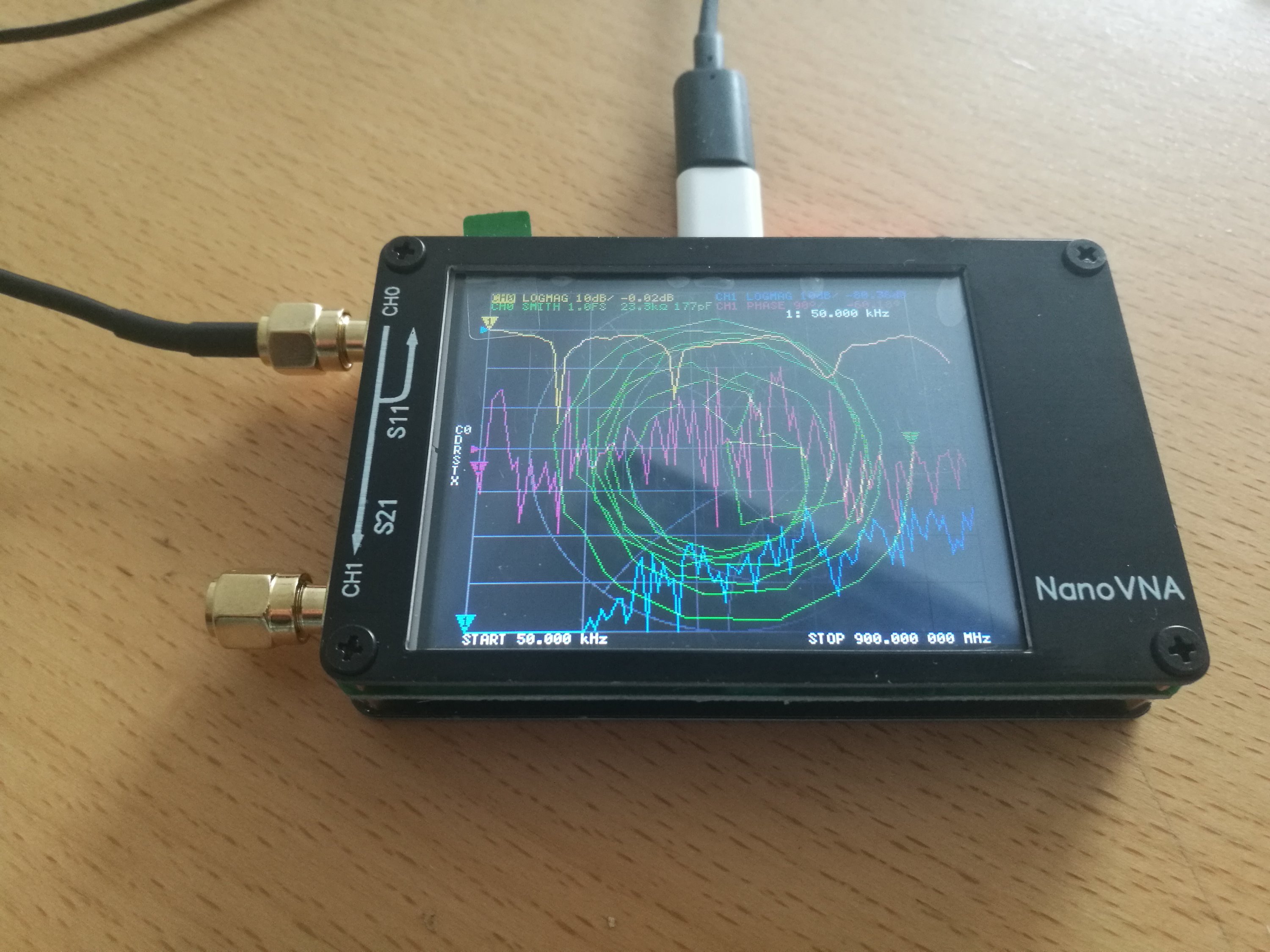
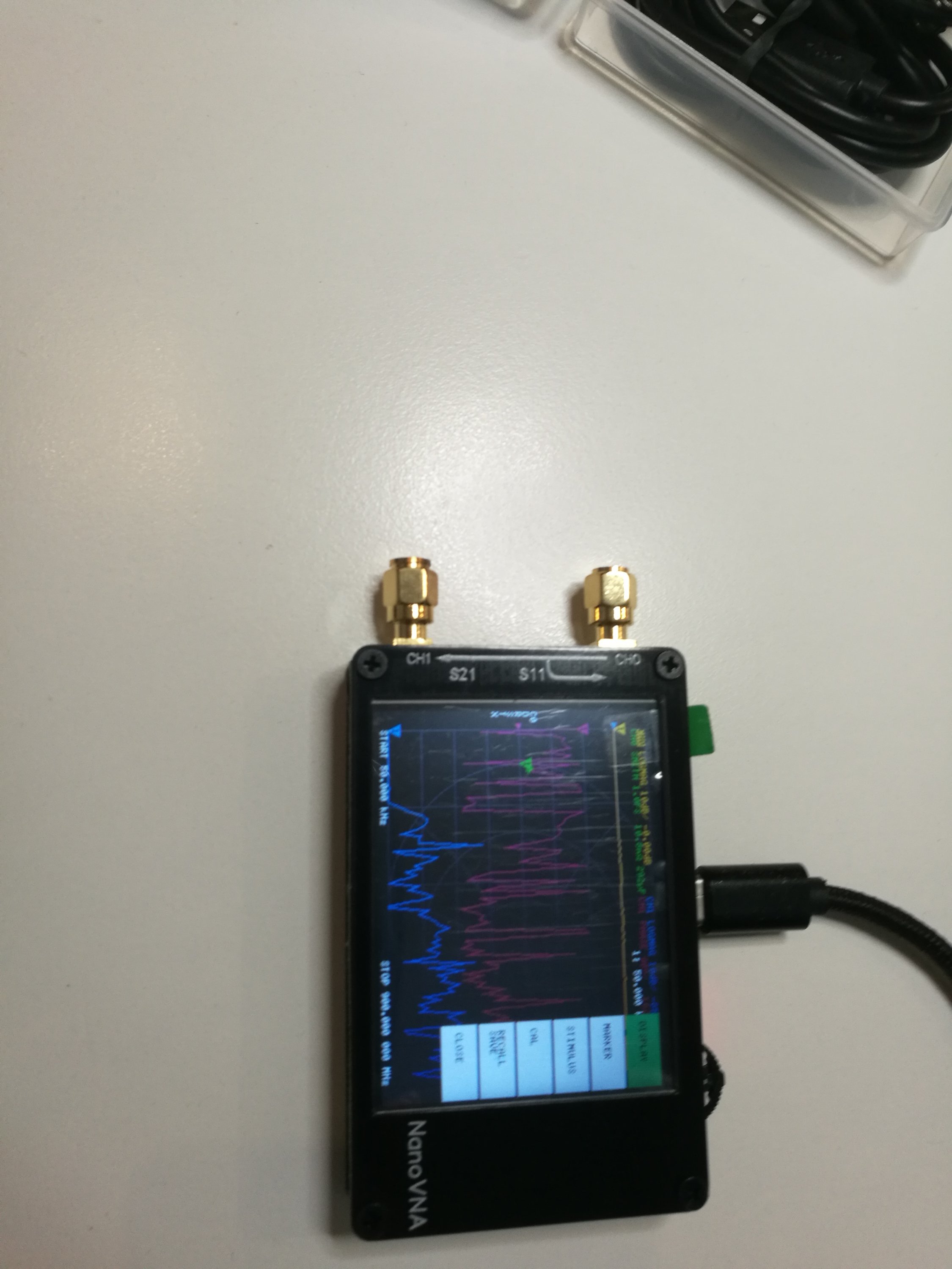
NanoVNA is advertised as a standalone device with LCD display, portable device with battery. It can also controlled with PC software.The frequency range is from 50 kHz to 900 MHz.  I had earlier posted some videos on this device to http://www.epanorama.net/newepa/2019/08/11/nanovna-handheld-vector-network-analyzer-vna/

There are a ton of people selling them out of China. I ordered mine from my trusted source Banggood.com that sells one for around $65. Here is the device I received:

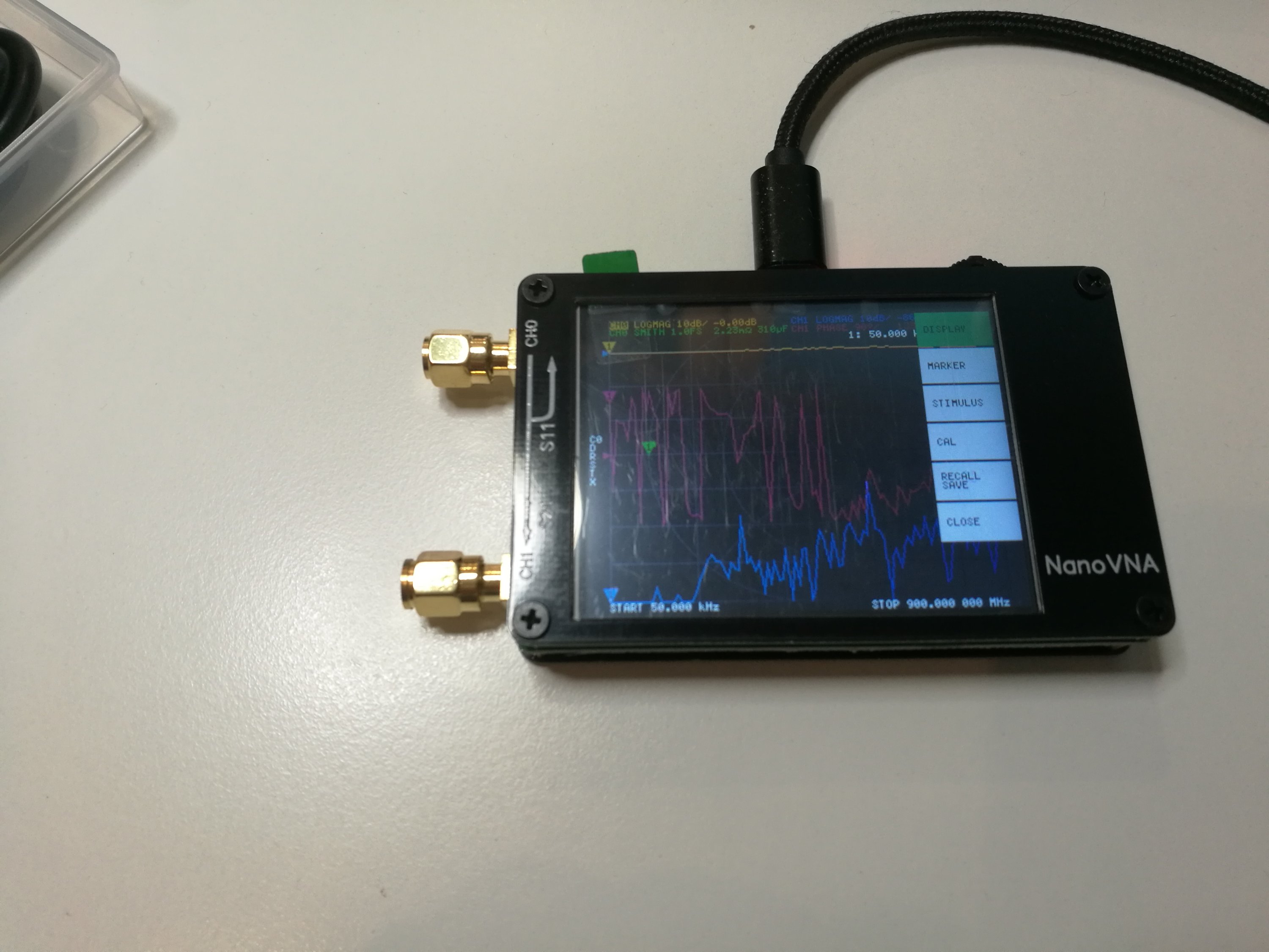
NanoVNA Vector Network Analyzer 50KHz – 900MHz Digital Display Touch Screen Shortwave MF HF VHF UHF Antenna Analyzer Standing Waveis a a DIY product with vector network measurement function. It includes a 2.8-inch touch screen, TX/RX measurement, can determine the complete S11 and S21 parameters (claimed that can be modified to measure S12 and S22). Here is the technical data from product page:

● RF output: -13dbm (maximum -9dbm)
● Measurement range: 70dB (50kHz-300MHz), 60dB (300M-600MHz), 50dB (600M-900MHz) enable extended firmware);
● Port SWR: < 1.1
● Display: 2.8 inch TFT (320 x240)
● USB interface: USB type-C communication mode: CDC (serial)
● Power: USB 5V 120mA, can use battery powered, maximum charging current 0.8A (battery Not included )
● Number of scanning points: 101 (fixed)

The firmware for the device is open source and available at https://github.com/ttrftech/NanoVNA. The device schematics are also available there.

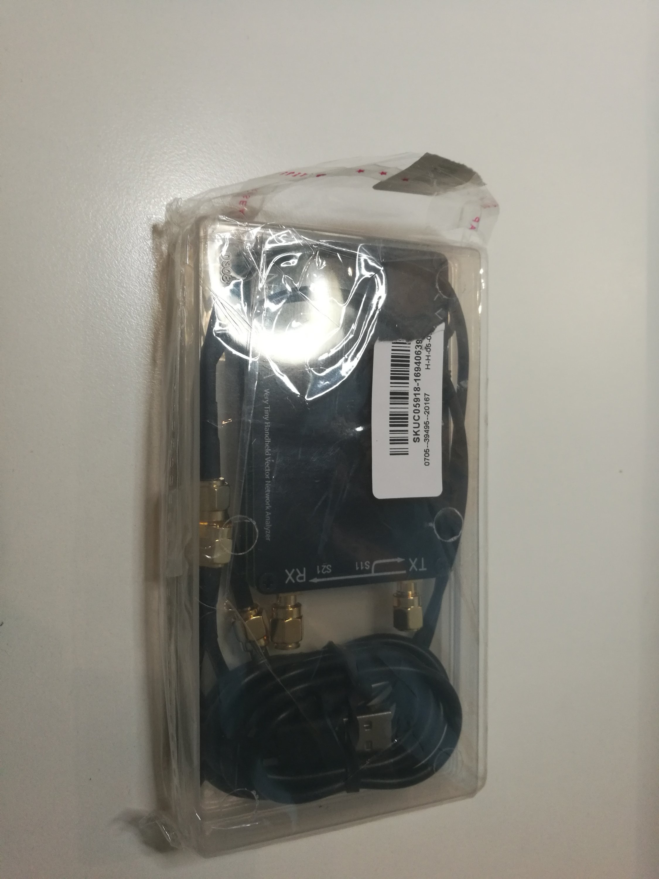
The product package included NanoVNA device, USB Type-C data cable, two 30mm SMA male to male cable and test connectors, one SMA female to female connector and calibration parts (SMA connector with open, short circuit and 50 ohms terminator). Everything came in a nice plastic box that is useful for storing and transporting all the parts.

This is a DIY product that provides quite nice vector network measurement capabilities in the size of a credit card. It includes a 2.8-inch touch screen. The TX/RX method can measure the complete S11 and S21 parameters. The device promises to provide 70 dB dynamic range for frequencies from 50 kHz to  300 MHz. That’s the basic frequency range the hardware was originally designed, but there are tricks that allow it to be extended.
The improved frequency algorithm can use the odd harmonic extension of si5351 to support the measurement frequency up to 900MHz but with somewhat lower dynamic range.The extended ranges 300M-600MHz band provides better than 60dB of dynamics, and the 600M-900M band is better than 50dB of dynamics.This is what the software supports, but tthere are some hacks that claims can go even higher above 1 GHz.
Besides all the great things, there here are also some small caveats. The first one is the touch display is on the small size, which makes it somewhat hard to operate with big fingers. The ruggedness of the unit feels a bit questionable with small tilt switch at the top and the sides of the device open. It works OK for a lab use when you are careful, but might not be able to take heavy field use like it is. The user  interface elements are a bit confusing, the fonts and color choices are not super legible. The calibration accessories I received were not labelled in any sensible way, but could be measured which is which.

There is also PC software to work with this device. The device home page had software package that included NanoVNA v1.01 software did not work for me. After some Googling I found a discussion on the problem with this software on some countries (it was . vs , issue on number presentation) and the discussion recommended to download NanoVNA v1.03 from https://drive.google.com/drive/folders/1IZEtx2YdqchaTO8Aa9QbhQ8g_Pr5iNhr. NanoVNA v1.03 worked for me.

There were also some Python software code that I did not try this time.

Other issues:

The device supports rechargeable LiPo batteries, but the batteries are not included on the model I bought because of the safety of international transportation. I also liked to have the LiPo battery installed on my device. The device has battery charging circuitry, so installing suitable LiPo battery should make it very portable instrument (500mAh battery should give offline for 2 hours). Getting suitable LiPo battery and installing it is for another article.

Sometimes I feel that it would be nice if this device has a full case. I saw one 3D printable case for NanoVNA at Thingverse. I have downloaded the files, but I have not yet had access to suitable 3D printer to print it.

Related postings:

http://www.epanorama.net/newepa/2019/08/11/nanovna-handheld-vector-network-analyzer-vna/

https://www.rtl-sdr.com/reviews-of-the-nanovna-an-ultra-low-cost-50-vector-network-analyzer/

http://www.bbrc.info/articles/nanovna

https://groups.io/g/nanovna-users

https://brainwagon.org/2019/09/02/first-test-of-the-nano-vna-on-my-beacon-antenna/

https://github.com/ttrftech/NanoVNA

https://hexandflex.com/2019/08/31/getting-started-with-the-nanovna-part-1/

https://mtmotorstables.blogspot.com/2019/08/reviews-of-nanovna-ultra-low-cost-50.html

Getting the device:

If you are interested in getting one, use this link https://www.banggood.com/NanoVNA-Vector-Network-Analyzer-50KHz-900MHz-Digital-Display-Touch-Screen-Shortwave-MF-HF-VHF-UHF-Antenna-Analyzer-Standing-Wave-p-1471576.html?p=27131452996820140438 to get the version I got. It seems that the same web shop has also a slightly cheaper version (white color) in pre-order at https://www.banggood.com/NanoVNA-Vector-Network-Analyzer-50KHz-900MHz-Digital-LCD-Display-HF-VHF-UHF-Antenna-Analyzer-Standing-Wave-USB-POWER-p-1549963.html?p=27131452996820140438

161 Comments

  1. Tomi Engdahl says:

    Checking Out TV Antennas With a $130 VNA
    https://www.tvtechnology.com/opinions/checking-out-tv-antennas-with-a-130-vna

    While searching for software for the miniVNA I came across the NanoVNA analyzer (Fig. 1). The original units have a 2.8-inch LCD screen and are about 54×85.5x11mm in size. Frequency range is 50 kHz to 900 MHz. I bought one for $53 from Amazon (shipped from China). These VNAs use an open source hardware design and quality varies greatly. Some units don’t even shield the RF components, and while most come in a plastic box with the calibration kit and cables, the VNA itself is just a stack of the metal back plate, circuit board and LCD with the sides open. Based on reviews I’ve seen online, the cheap units that have a replica of the Copper Mountain lizard logo on them are the worst. Amazon prices have gone up due to tariffs, but most are still under $75.

    Before you get too excited about these low-cost VNAs, there are some significant limitations. The maximum output power is around –9 dBm for the NanoVNA and –6 dBm for the miniVNA. Available software doesn’t appear to have an option to eliminate interference from the strong signals likely to be present at a broadcast antenna site.

    Even with these limitations, I find the NanoVNA useful and worth packing in my travel kit. Fig. 1 shows a test setup I used to measure a Channel Master LTE filter; Fig. 2 shows the results. For this measurement I used minimum loss 50 ohm to 75 ohm pads to present the proper impedance to the filter and calibrated the VNA at 75 ohms with a homemade 75 ohm cal-kit. As you can see, the drop off above 698 MHz is quite steep, but we’ll need a new version that cuts off frequencies above 608 MHz once the incentive auction repack is finished next year as I’m already seeing strong cellular signals popping up in the new 600 MHz wireless band.

    Reply
  2. Tomi Engdahl says:

    Can I use a 50 ohm network analyzer to measure 75 ohm devices?
    https://www.keysight.com/main/editorial.jspx?ckey=1000002208:epsg:faq&id=1000002208:epsg:faq&nid=-11143.0.00&lc=fin&cc=FI

    This is generally not recommended since a 50 ohm test set is optimized to measure at 50 ohms. Measuring 75 ohm devices on a 50 ohm test set is not as accurate as measuring on a 75 ohm test set. However, it can be done. Here are the procedures and the caveats.

    Method One:

    Attach a 50 to 75 ohm pad and calibrate at the 75 ohm plane with a 75 ohm calibration kit with the system impedance set at 75 ohms. The raw directivity is degraded by twice the value of the pad in dB.

    Method Two:

    Use a 50 to 75 ohm mechanical adapter. Again, calibrate at the 75 ohm plane with a 75 ohm cal kit with the system impedance set at 75 ohms. Mismatch effects will affect the accuracy of the calibration and measurement. The Keysight model 11852B minimum loss pad provides a 50 to 75 ohm impedance matching function from DC to 3GHz. The standard model has a Type-N(f) 50 ohm connector and a Type-N(m) 75 ohm connector. Option 004 provides a Type-N(m) 50 ohm connector, and a Type-N(f) 75 ohm connector.

    Revision 2.0 25 January 2000

    Reply
  3. Tomi Engdahl says:

    Using NanoVNA To Measure Inductor Q
    https://robs-blog.net/2020/06/02/using-nanovna-to-measure-inductor-q/

    How good are those inductors you just wound? What about those inductors you just bought from your favorite online store? Don’t know? Well knowing the Q of the part is going to help you know whether they are going to be useful in that bandpass filter or oscillator and it could not be simpler if you have a nanoVNA.

    Reply
  4. Tomi Engdahl says:

    Nano VNA Saver
    Was given a link to this new software. Man this is much better than the software that came from china.
    https://robs-blog.net/2019/10/05/nano-vna-saver/

    Reply
  5. Tomi Engdahl says:

    NANO VNA Calibration
    https://robs-blog.net/2019/10/04/nano-vna-calibration/

    So long story. I have had some trouble getting the Nano VNA to hold a calibration and display the correct information. I always had a -10db offset when using certain SMA leads i had there. It would display fine with semi rigid SMA leads, but, others would show -10db. Like the leads had loss in them.

    Well anyway, I think i have resolved the issue and got the calibration right. 0.5db loss in my leads would be about right and that is what is showing now, they are after all cheapest crap leads from China, not high end leads you would use in a lab.

    So anyway, popper calibration procedure.

    Open: Open Load on S11 port.
    Short: Short load on S11 port.
    Load: 50 ohm load on S11 port.
    Isolation: 50 ohm load on both S11 and S21 ports.
    Through: Shortest high quality 50 ohm cable connecting S11 and S21 together.

    Then save that. That is it, that should then give you fairly accurate, well as accurate as the NANO VNA is results. As you can see by the plot of a 40m bandpass filter above, it looks about what you would expect from a known design that has low insertion loss. A couple of dB, made up of the lead loss and the filter loss. This means my filter has about 1dB insertion loss. That is something I can live with.

    Reply
  6. Tomi Engdahl says:

    RF Sampler
    I build this the other day also after making the new dummy loads. So much test gear so little time LOL.
    https://robs-blog.net/2019/07/05/rf-sampler/

    Reply
  7. Tomi Engdahl says:

    CALIBRATION WITH SO-259 NANOVNA
    https://it9ybg.blogspot.com/2020/11/calibration-with-pl259-nanovna.html?m=1

    directly connect antennas with SO-239 and have exact calibration at the output of the SO connector.

    Reply
  8. Tomi Engdahl says:

    Bad NanoVNA-F Clones showing up
    https://groups.io/g/nanovna-users/topic/62208443?p=,,,20,0,0,0::,,,0,0,0,62208443

    Reply
  9. Tomi Engdahl says:

    https://www.facebook.com/groups/368777730463838/permalink/672552426753032/
    If you are just starting out with the NanoVNA or are an intermediate level user this presentation by Alan Wolke (W2AEW) will answer many questions and help you become more proficient with this device. His many years of experience as an RF engineer and his ability to discuss technical concepts in an easy to understand manner makes for a high quality technical video. It is on YouTube so you can go into settings and speed up the sound or add captions if you are a non-English listener.

    G-QRP Club 2020 Convention : Alan Wolke W2AEW: VNAs Explained and the NanoVNA
    https://m.youtube.com/watch?v=f52LHhuOROM

    Reply
  10. Tomi Engdahl says:

    If you want practical understanding of how to use Smith Charts watch w2aew YouTubes. The guy is a legend.

    https://youtu.be/f8MhMl4IqUE

    https://youtu.be/TsXd6GktlYQ

    Are just two. Search youtube for W2AEW Smith charts and when you are done start watching his entire, fabulously well made catalogue.

    Reply
  11. Tomi Engdahl says:

    The #math behind the #SmithChart #LivingAnalog
    https://buff.ly/3bksdO4

    Reply
  12. Tomi Engdahl says:

    How not to damage your NanoVNA when measuring SWR
    https://m.youtube.com/watch?v=totwu4IbavE

    This video describes the basics of how to protect the sensitive NanoVNA when making SWR measurements.

    Reply
  13. Tomi Engdahl says:

    If you have common mode noise issues, the common mode ferrite chokes attenuation can be measured with NanoVNA as described on the below video.

    https://www.youtube.com/watch?v=fEsmarnM6nE

    Comparing the NanoVNA with Rigol DSA815, I’ve got similar results.
    Up to 0.4dB difference sounds good for the NanoVNA price.

    Reply
  14. Tomi Engdahl says:

    Smith Chart Basics + VNA Paperclip Test
    https://www.youtube.com/watch?v=lUkPjqOoJQU

    Today we’re going explore Smith Chart basics, and then use that information to learn about the RF performance of a paperclip. Would this make a good antenna, at what frequencies does it resonate?
    A Smith chart makes this really easy to see.

    Smith Charts look scary at first, but they’re not once you know what’s going on. Let’s start with a complex impedance, say .5 + j1.1.

    If you plot out this impedance on the complex plane, our X-Axis is our real component, or resistance, and the Y-Axis is our imaginary component, or inductance and capacitance. Inductors are positive, capacitors are negative. And you can plot it! We see where our real component .5 and our imaginary component, 1.1, meet, and we plot it. Simple Algebra 1 stuff.

    A smith chart is basically this graph, but you curl it in on itself into a circle.

    This might seem weird, because all of these axis go to infinity. It would be hard to plot infinity resistance on this, but with the Smith Chart we can. And, an open circuit is infinite resistance, infinity is not some weird edge case for electronics – open circuits are everywhere!

    So to plot the same .5 + j1.1 on the Smith Chart, we do the same thing we did before, we find .5 on the real axis, and +1.1 on the imaginary axis and draw a spot where they meet. It’s Algebra 1 but it’ll impress and confuse all the business majors.

    We have an open circuit – infinite impedance on the far right, and a short circuit or 0 impedance on the far left. And literally everything in between.

    The Smith chart now gets more complicated for two reasons. Reason number one is that all this is normalized information.

    For example, RF folks like 50 ohm systems, so if we had an impedance of 75 + j40, we’d end up with a normalized impedance of 1.5 + j.8 and we can plot it.
    In an ideal world, our generator and load are impedance matched, so we end up with 1 + j0 right in the middle. We get the best transmission, the transmission coefficient is 1, the reflection coefficient is 0, and our VSWR is 1. The Smith Chart tells us that! We can also use this information to design impedance matching networks to move a point from non-ideal to ideal. This is easier with a combined smith chart that has both impedance and admittance, but we’re not going there today.

    The second reason this gets complicated is that impedance is dependent on frequency. And everything is a combination of resistance, inductance, and capacitance. So, naturally, as our frequency changes so does our impedance.

    So at one frequency we have one nice point, but in RF engineering we care about a range of frequencies so we often end up with some sort of curve as our frequencies change. This is really nice, though, because we get a picture of our system as frequencies change.

    Reply
  15. Tomi Engdahl says:

    nanoVNA-H – a ferrite cored test inductor impedance measurement – s21 series vs s11 reflection
    https://owenduffy.net/blog/?p=16088

    Conclusions
    There is great benefit in direct reading of R and X, benefit that should not be overlooked.

    Uncertainty in Zin of Port 2 rolls up into uncertainty of s21 series impedance measurement.

    An attenuator can be used to better control Port 2 Zin, but at the expense of noise performance.

    Common mode chokes with high impedance are very sensitive to stray capacitance and distributed inductance of connections, and the measurer must consider the design of a test fixture appropriate to the deployment.

    In the case of common mode chokes with high impedance one is less interested in the peak impedance values, or even impedance at some specific frequency (since it may be very sensitive to stray capacitance), but rather the range of frequencies where common mode impedance exceeds some criteria.

    Reply
  16. Tomi Engdahl says:

    nanoVNA-H – measure ferrite core permeability
    https://owenduffy.net/blog/?p=16124

    This article demonstrates the use of the (modified) nanoVNA-H to capture data from which the complex relative permeability of an unknown ferrite core is calculated and plotted

    Reply
  17. Tomi Engdahl says:

    NanoVNA and Mix #31 Ferrite Bead
    https://www.youtube.com/watch?v=MRUwBTD2zEU

    I used some Mix 31 Ferrite beads from a hamfest to cure a little RFI getting into my audio amp in the shack. This video explains how I confirmed the material was #31 mix. NanoVNA and nanovna-saver software is used. You can also see how effective this material is from 1 to 30 MHz – ideal for HF RFI issues.

    #766​ Measuring Ferrite RFI Suppression
    https://www.youtube.com/watch?v=4Gh4EC02LsA

    Reply
  18. Tomi Engdahl says:

    Measuring Toroid Attenuation
    https://0×9900.com/measuring-toroid-attenuation/

    I am going to show you two ways to test the ferrite cores you have collected over the years.

    Reply
  19. Tomi Engdahl says:

    #95: Three Methods to Measure Impedance with the NanoVNA
    https://youtu.be/1UbEz73FGCU

    Julkaistu 2.3.2020
    Are you aware that there is more than one method to measure impedance with a VNA? You might find this video interesting.

    Reply
  20. Tomi Engdahl says:

    One idea for measuring losses on impedance matching transformers and baluns is connect two identical transformers in series in opposite direction. Measure loss over two series connected transformers and the divide this loss evenly with those transformers to get number for one.

    Reply
  21. Tomi Engdahl says:

    This article demonstrates the use of the (modified) nanoVNA-H to measure Loss (Transmission Loss) and Insertion Loss of a small ferrite 64:1 RF transformer, and the Insertion VSWR and Return Loss.
    https://owenduffy.net/blog/?p=16139

    Reply
  22. Tomi Engdahl says:

    Back to Back transformer Measurement on SDR-Kits Test board
    https://groups.io/g/nanovna-users/topic/74777580?p=Created,,,20,2,0,0::,,,0,0,0,74777580

    Reply
  23. Tomi Engdahl says:

    nanoVNA-H – measure ferrite core permeability
    https://owenduffy.net/blog/?p=16124

    This article demonstrates the use of the (modified) nanoVNA-H to capture data from which the complex relative permeability of an unknown ferrite core is calculated and plotted

    https://owenduffy.net/calc/toroid.htm

    Reply
  24. Tomi Engdahl says:

    Here is a one transformer method that works very well. https://groups.io/g/nanovna-users/message/21346?p=,,,20,0,0,0::Created,,2450,20,2,0,81302394

    Reply
  25. Tomi Engdahl says:

    Read the entire transformer measuring discussion here…. https://groups.io/g/nanovna-users/topic/81302394#21334

    Reply
  26. Tomi Engdahl says:

    Calibrating A VNA The Proper Way
    https://hackaday.com/2021/05/08/calibrating-a-vna-the-proper-way/

    Those of us who have bought cheap TinyVNA devices for our RF experimentation will be used to the calibration procedure involving short-circuit, 50 Ω, and open terminations, followed by a direct connection between ports. We do this with a kit of parts supplied with the device, and it makes it ready for our measurements. What we may not fully appreciate at the level of owning such a basic instrument though, is that the calibration process for much higher-quality instruments requires parts made to a much higher specification than the cheap ones from our TinyVNA. Building a set of these high-quality parts is a path that [James Wilson] has taken, and in doing so he presents a fascinating discussion of VNA calibration and the construction of standard RF transmission line components.

    https://jmw.name/projects/vna-standards/

    Reply
  27. Tomi Engdahl says:

    The NanoVNA does not have enough dynamic range to tune a duplexer properly. https://www.youtube.com/watch?v=GipCVEsiqXc

    Reply
  28. Tomi Engdahl says:

    NanoVNA compared to an HP VNA
    https://m.youtube.com/watch?v=M0eJYoNzxH0

    Let’s compare the nano with an expensive HP unit (big and old but good).

    Reply
  29. Tomi Engdahl says:

    Debates Virtuais #003 – NanoVNA An Antenna Stethoscope
    https://m.youtube.com/watch?v=wODfReP7u4E&feature=youtu.be

    Reply
  30. Tomi Engdahl says:

    NanoVNA Sorts Unknown Ferrite Suppression Beads
    YouTube · Fair-Rite Products Corp.
    1 month ago
    https://youtu.be/KmKQibSDzqM

    Reply
  31. Tomi Engdahl says:

    nanoVNA-H – measure ferrite core permeability
    https://owenduffy.net/blog/?p=16124

    Reply
  32. Tomi Engdahl says:

    Trying to understand something here… When calibrating the VNA why do we have to put an open “standard” on the connector? Why can we not just do the open calibration with the socket left just open, nothing attached at all?

    This is related to the reference plane. Have a look at W0QE, Larry Benko’s excellent video on the topic : https://www.youtube.com/watch?v=xLGSblc-Fec&t=85s
    Larry has made over 100 videos on SimSmith, which is free software. If you want to look into his videos, start at #8, which is the first of SimSmith Basics videos.

    Reply
  33. Tomi Engdahl says:

    NanoVNA to measure the complex choking impedance of various common mode chokes, but I’m not sure how best to do so with my device.

    I’m sure many are familiar with Steve G3TXQ’s site. He has links describing his process at the bottom of the main page. Link: http://www.karinya.net/g3txq/chokes/

    I’ve found this resource as well, which shows an individual using two BNC to binding post adapters instead of Steve’s more physically complex arrangement. Also, importantly, this individual does not show complex impedance, but rather just shows relative magnitude. Link: https://www.hamradio.me/antennas/where-a-choke-chokes.html

    Reply
  34. Tomi Engdahl says:

    Make Accurate Impedance Measurements Using a VNA
    June 21, 2019
    Three different methods can be applied to accurately measure passive components with a vector network analyzer.
    https://www.mwrf.com/technologies/test-measurement/article/21849791/copper-mountain-technologies-make-accurate-impedance-measurements-using-a-vna

    Reply
  35. Tomi Engdahl says:

    nanoVNA – S11 Phase
    https://m.youtube.com/watch?v=gl3UMF6xtHM&feature=youtu.be

    Is the phase angle displayed on the nanoVNA a measurement of the phase relationship between voltage and current in the DUT?

    It is easy to come to the conclusion that the S11 phase angle as seen on the nanoVNA is the relationship in a device under test between the voltage and current in that device, and I once fell down that hole myself. Haha! After finding that the S11 phase readings on the nanoVNA didn’t make sense when thought of as representing the voltage vs current relationship in the device under test I quickly knew that I must have missed something in my understanding of how the VNA works.

    This video explains my findings.

    Reply
  36. Tomi Engdahl says:

    Buy a NanoVNA
    https://nanovna.com/?page_id=121

    For platforms such as Amazon or AliExpress, please buy directly through the store provided by the link. Other advertising links on the platform may sell bad clones.

    Reply
  37. Tomi Engdahl says:

    Teardown of a LiteVNA Vector Network Analyzer
    http://www.kerrywong.com/2022/03/22/teardown-of-a-litevna-vector-network-analyzer/

    LiteVNA current has two versions: LiteVNA 62 and LiteVNA 64. Besides LCD screen sizes (2.8 inch for the 62 model versus 3.95 inch for the 64 model) and battery capacities (1.3 Ah for the 62 model versus 2 Ah for the 64 model), all other technical aspects are identical. The model I got here is the LiteVNA 62.

    Unlike the NanoVNA-F V2 which is enclosed in a metal case, the LiteVNA comes in a plastic case with no additional shielding. But the build quality looks quite decent.

    https://eleshop.eu/litevna.html

    The LiteVNA is a portable 50 kHz – 6.3 GHz vector network analyzer which design is based on the NanoVNA and SAA2. This vna is designed to measure equipment reflection and transmission coefficients without the need for a large analyzer. The LiteVNA uses one mixer which enables S11 and S21 measurements through RF switching and TDR/DTF measurements through IFFT calculations.
    The analyser has a 2.8″ touch-screen display that can show the measurements in 10-1001 data points. Furthermore, the analyser has a built-in 1300 mAh battery and can be connected to an android phone or PC. Connecting to a phone or PC allows for controlling the analyser and displaying the measurements.

    Reply

Leave a Comment

Your email address will not be published. Required fields are marked *

*

*