A signal generator is an electronic device that generates repeating or non-repeating electronic signals in either the analog or the digital domain. These generated signals are used as a stimulus for electronic measurements.
There are many different types of signal generators with different purposes and applications. For analogue signal generation I have used for very years function generators, both DIY circuits and commercial devices.
For some time I have been thinking of getting somewhat better signal generator than what I already have, preferably an arbitrary waveform generator that support modulation. AWGs can generate any arbitrarily defined waveshape as their output.
One day some time ago I found product FY6800 2-Channel DDS Arbitrary Waveform Signal Generator 14bits 250MSa/s Sine Square Pulse Frequency Meter VCO Modulation for sale at attractive price.
FY6800 series of Dual-channel Function / Arbitrary waveform generator products (several versions at different supported frequency range) promise a nice set of features: Dual-channel Signal Generator, Arbitrary Waveform Generator, Pulse Generator, Analog / Digital modulator, VCO and Sweep. In addition this product has a built-in Frequency Meter. It seems to have nice looking graphical display to operate it marketed with “Abundant shortcut keys and graphical user interface simplifies every operation.” This product is marketed for education, research and development, production, testing, maintenance and other industries. The instrument promises to use Direct Digital Synthesizer (DDS) technology and provide stable, precise, pure and low distortion signals.
FeelTech FY6800 product page tells that this product uses a professional 14Bit high-speed D/A chip instead of a 12-bit D/A resistor network used in some earlier products. This promises to deliver higher the resolution and smoother waveform details. This product supports waveform memory depth upgrade to 8192 * 14bits up to sampling rate 250MSa/s. The maximum output signal amplitude range is1mVpp~20Vpp. The maximum frequency range of sine wave is 1uHz~60MHz, the maximum range of square wave is 1uHz~25MHz, other wave frequency range is 1uHz~20MHz (rising edge time within the square wave 5V is as low as 7nS). When used as pulse generator the pulse width to be accurately set between 20nS-1S.
After viewing and reading reviews I got the feeling that this product can full-fill the promises it gave. FY6800 is an improvement over the earlier signal generators from the same manufacturer.
#494 Feeltech FY6800 60MHz AWG Signal Generator Review
FeelTech FY6800 60MHz Signal Generator / Counter Review
QTR 37 BangGood 2 Ch 60Mhz Arbitrary Waveform Generator FY6800
For more detailed tech specifications view or download the user guide. You can download software and manuals from Google Drive.
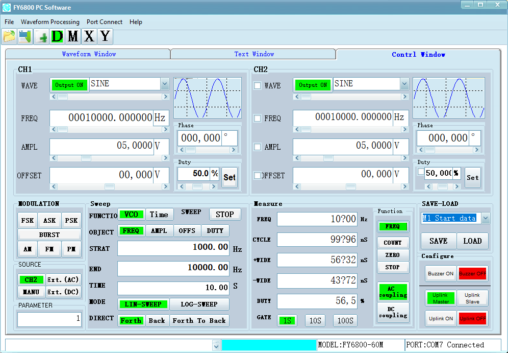
The instrument has presets for 33 kinds of common waveforms for the user, but also provides users with up to 64 groups (8192 * 14Bit) of user-defined waveform storage space. The user can use the host computer with provided software to upload the waveform and control the instrument settings. The Windows 10 application works mostly, but could be better.
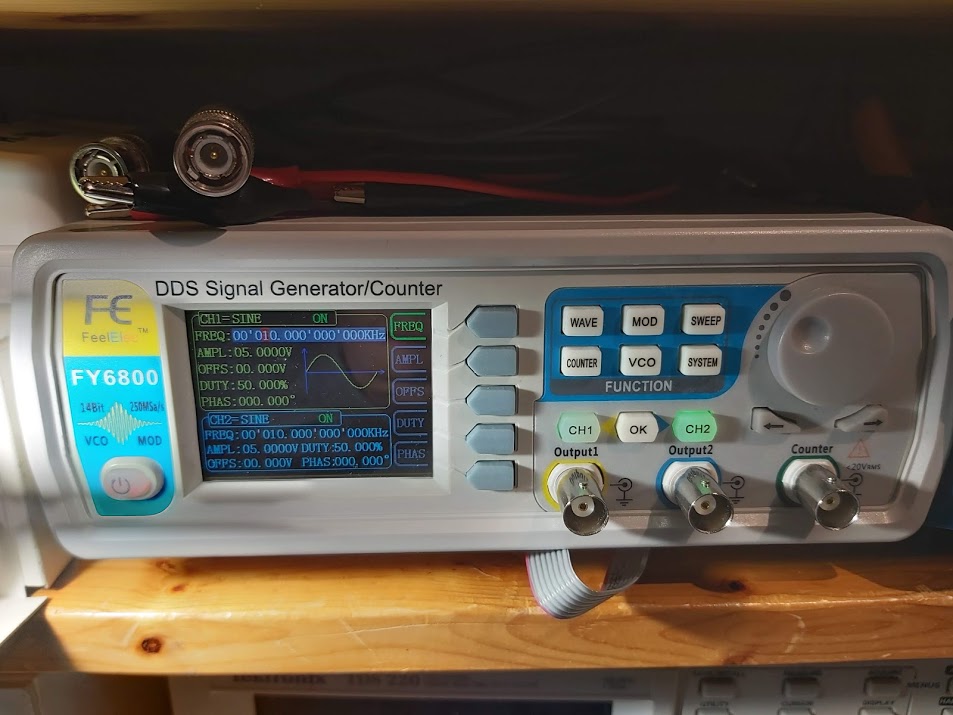
I like the display. The two-channel waveforms are displayed on the LCD interface at the same time. The user interface with the control buttons and rotating control know if quite good and intuitive to use.
The signal outputs work well as specified. Both signal outputs have 50 ohms impedance and seem to do what promised on the specifications.
On the back of the instruments there is 8 pin connector for TTL level signals like signal generator outputs and access to serial communications. There are 4 TTL outputs that output differential signal version of the signal generator channels 1 and 2. Those output signals seem to be 3.3V TTL level, which is quite handy when working with logic signals.
This device supports the external analog voltage on the instrument output frequency, amplitude, duty cycle, bias Level modulation. There are BNC connectors on the back to feed in the modulation signals.
This signal generator has nice measurement function built into it. The instrument can measure the signal frequency, period, positive pulse width, negative pulse width and duty cycle. All measured parameters are displayed in the same interface and can be also seen with PC software if needed. The maximum measurement frequency of the instrument can reach 100MHz, and the minimum measurement frequency is 0.01Hz. The counter is designed to accept signals that are more than 200 mV RMS quite well. The maximum signal voltage listed on the device panel is 20V.
The Windows 10 application works mostly, but could be better. For example on my Windows 10 (Finnish Versions) some symbols on the display (for example measurement results) did not display correctly. The application also seemed to crash and loose USB connection to the generator sometimes.
Communicating with the device from own software:
My FY6800 signal generator uses FY6600 Serial communication protocol that is based on serial communications (normally performed over USB). The baud rate is fixed value 115200bps.
The overall structure of control command consists of command line, where each command end to a newline (hexadecimal “0x0a”). The execution machine will reply 0x0a after command executed. The commands are issued by PC and they are analyzed by signal generator CPU. The protocol is ASCII text based. Each command line starts with command followed by command parameters. Each command line starts with a three letter command code.
You can download example code and documentation from Google Drive.
Here is a video that give view to what is inside this signal generator:
FeelTech FY6800 Review & Teardown
Here are some project ideas for experiments with RY6800:
FY 6800 Generator as Beacon web page shows how to create BPSK , RTTY, Hellschreiber, CW, WSPR beacon with FY6800 generator. This project uses FY6800 and Arduino. You will be find all schematics and the serial protocol here: https://github.com/f4goh/FY6800Beacon
15 Comments
Justina Baker says:
I got my fy6800 today and went through 4 hours searching for the PC programming. I didn’t discover it. Would you be able to give a source? It would be most value any assistance.
Tomi Engdahl says:
You can download software and manuals from Google Drive at
https://drive.google.com/drive/folders/1N9M_yK9sdabVUyatPqLINeHnVQR3yKqN
Tomi Engdahl says:
https://robs-blog.net/category/amateur-radio/construction/test-equipment/
https://robs-blog.net/2020/10/17/am-modulation-feeltech-fy6600/
Ashley Blossom says:
Hi,
I got my fy6800 generator a few months back but now this is not working correctly. There’s a break in an analog signals and sometimes in digital as well. Yet I haven’t get the same. Kindly share if anyone can provide me the website for electronic products.
Ashley Blossom says:
Hi,
I got my fy6800 generator a few months back but now this is not working correctly. There’s a break in https://acemyassignment.co.uk/ an analog signals and sometimes in digital as well. Yet I haven’t get the same. Kindly share if anyone can provide me the website for electronic products.
ashly says:
The diver can experience a different underwater environment at night, because many marine animals are nocturnal.
shane says:
We use these generator.
Tomi Engdahl says:
EEVblog 1431 – Keysight EDU33212A Function Generator Teardown
https://www.youtube.com/watch?v=pH-FySpUk84
Teardown of the new Keysight EDU33212A 20MHz Function Generator
https://www.eevblog.com/forum/blog/eevblog-1431-keysight-edu33212a-function-generator-teardown/
Tomi Engdahl says:
Poor Man’s “Bode Plot” with FY6800 Signal Generator and Oscilloscope
https://www.youtube.com/watch?v=ydJcsw4tD6I
Curb your expectations, there’s a reason for the quotation marks in the title. You won’t see a real Bode plot in this video, at least not on the scope. We’ll go for a poor man’s frequency response measurement, magnitude only.
Intro …
00:00 Intro – curbing expectations, looking at viewer questions
04:46 Bode plots – frequency response of a circuit visualized
09:37 Frequency sweeps – Bode plots automated
Frequency sweeps using VCO …
13:19 VCO linearity – reports of its non-linearity are greatly exaggerated, but it sucks anyway
22:09 Voltage ramp – controlling the VCO with a signal the oscilloscope can trigger on
27:48 Summary – nice for a qualitative analysis, but not for quantitative measurements
Frequency sweeps using FM …
32:39 FM linearity – reported as better than the VCO’s, but it’s actually worse
38:39 Summary – same setup as for the VCO, worse performance than the VCO
Audio amplifier as DUT …
40:51 Audio amplifier as DUT – you always wanted to know how a frequency sweep sounds
Wrap-up …
45:07 Wrap-up – it’s fun and it certainly has its uses, but not for quantitative measurements
Viewer comments:
I have found another way to achieve this that I believe is more accurate. Simply pass the trigger output through a low-pass filter and a peak detector. This will produce a signal that has a rising edge only at the start of the sweep. This you can use to trigger the scope. To produce a log log diagram you can set the sweep to be logarithmic and you can use the math channel of the scope to log the y-axis.
A very simple and elegant solution! But it’s kind of cheating using extra hardware
But then, it’s not cheating … if it yields better results Any yes, I guess everybody can cobble together a RC low pass, a diode peak detector and two BNC sockets if the need arises – no PCB necessary. Put the whole thing into a copper or steel tube with the BNC sockets sealing the openings and you’re done.
Tomi Engdahl says:
FY6800 Signal Generator
https://tech.scargill.net/fy6800-signal-generator/
FY6800 Series Fully Numerical Control
Dual Channel Function/Arbitrary Waveform Generator
User’s Manual
https://gotronik.pl/images/FY6800Manual.pdf
Tomi Engdahl says:
Module: FY6xxx FeelElec FY6800 serial communication protocol library for python
https://github.com/NikkiGirl/FY6xxx
Tomi Engdahl says:
#45: Sweep Generator Basics and Receiver Alignment
https://www.youtube.com/watch?v=-A_DxsxPdeI&t=300s
EEVblog #396 – Bode Plotting on Your Osciloscope
https://www.youtube.com/watch?v=uMH2hGvqhlE
Dave shows you a neat trick on how to get a real time frequency response bode plot on your oscilloscope using your function generator. Useful for filter or system response characterisation.
Tomi Engdahl says:
https://www.eevblog.com/forum/beginners/using-sweep-generator-and-a-scope-to-display-filter-response-fy6800-suitable/
Tomi Engdahl says:
Build a Flexible Arbitrary Signal Generator
March 28, 2022
https://www.electronicdesign.com/technologies/analog/article/21237367/toshiba-europe-build-a-flexible-arbitrary-signal-generator
Discover how to produce a multiple output arbitrary signal generator cheaply and quickly with low-cost, hobbyist-level microcontroller development boards.
Jennifer Taylor says:
This will produce a signal that has a rising edge only at the start of the sweep. This you can use to trigger the scope.