This is a continuation to my Power inverter designs post. The first post was about general details of inverters and square wave inverters. Because square wave inverters are not suitable for many applications. The next better inverter category is so called modified sine wave inverter.
Modified sine wave inverters are less complicated than sine wave inverters (the best king) but they may not successfully run some appliances, and they may produce a hum. These are not recommended for an average house with many electronic appliances and are not very common now.
Most inexpensive consumer power inverters produce a modified sine wave rather than a pure sine wave. Modified sine wave inverters are less complicated and less expensive than real sine wave inverters, but the downside of them is that they may not successfully run some appliances, and they may produce a hum.
Numerous items of electric equipment will operate quite well on modified sine wave power inverter devices, especially loads that are resistive in nature such as traditional incandescent light bulbs. Items with a switch-mode power typically supply operate almost entirely without problems. Switch-mode power supply (SMPS) devices, such as personal computers or DVD players, function on modified sine wave power. Inductive load like transformers and motors may operate less efficiently owing to the harmonics associated with a modified sine wave and produce a humming noise during operation. If an electronics device has a traditional mains transformer, this can overheat depending on how marginally it is rated.
While it is technically true that a modified sine wave inverter can potentially damage certain types of electronic devices, that’s really more of the exception than the rule. There are two main types of electronics that you need to be concerned about when using a modified sine wave inverter: appliances that use AC motors and certain classes of delicate medical equipment. If your electronics don’t fall into either of those categories, then it’s extremely unlikely that a modified sine wave inverter will do any damage. AC motors directly operated on non-sinusoidal power may produce extra heat, may have different speed-torque characteristics, or may produce more audible noise than when running on sinusoidal power. Most AC motors will run on MSW inverters with an efficiency reduction of about 20% owing to the harmonic content. However, they may be quite noisy.
The waveform in commercially available modified-sine-wave inverters resembles a square wave but with a pause during the polarity reversal. The modified sine wave output of such an inverter is the sum of two square waves one of which is phase shifted 90 degrees relative to the other. The result is three level waveform with equal intervals of zero volts; peak positive volts; zero volts; peak negative volts and then zero volts. This sequence is repeated. The resultant wave very roughly resembles the shape of a sine wave.
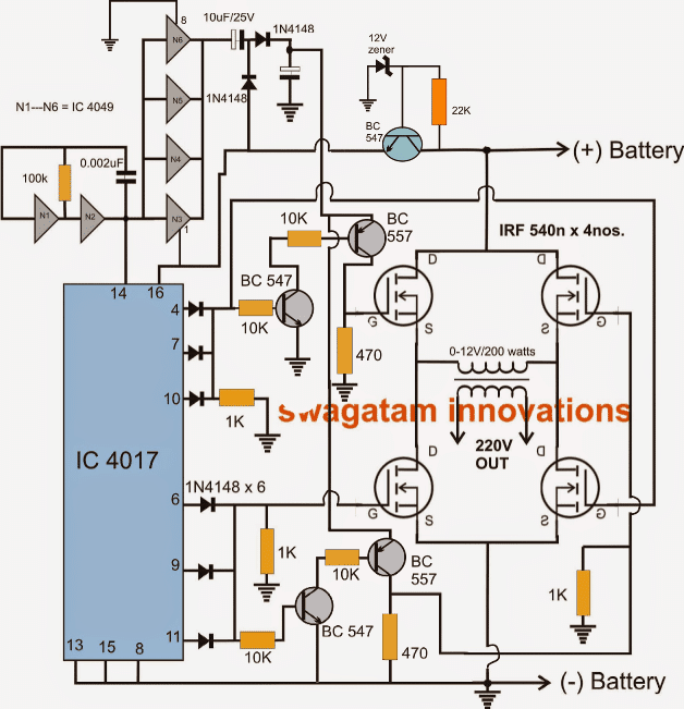
Let’s analyze one modified sinewave inverter project design (just found on-line and I have not tested in practice). The project at https://electronics-project-hub.com/modified-sine-wave-inverter-circuit/ is going to construct a modified sine wave inverter circuit using IC 555 and IC 4017. Here is the waveform picture and circuit diagram.


The circuit operation s quite simple. The 555 timer IC based oscillator circuit produces the necessary clock signal for this inverter that is fed to the IC 4017 IC that generated the needed control signals for transistors to produce 50Hz AC modified sine wave output. In this circuit the CD 4017 divides the incoming clock by four, so the clock frequency needs to be 200 Hz. The CD 4017 has four of it’s outputs (Q0-Q3) activated sequentially after each other. They are wired to transistors so that first activated Q0 turns on transistor that generated positive output, then Q1 is not connected to anything so this time output transistors are off, then Q2 is wired to transistor that generated negative voltage to output, and finally Q3 is not connected to anything to transistors are off. An ordinary step-down transformer in reverse to step-up the low voltage to standard 230V/110 VAC.
Other project links:
Web page https://teaelectronics.wordpress.com/2012/01/12/simple-12v-to-220v-modified-sine-wave-inverter-using555-timer-ic-and-cd4017/ describes a simple 12V to 220V modified sine-wave inverter using555 timer IC and CD4017.
Web page https://www.instructables.com/id/Modified-Sine-Wave-Signal-Generator/ describes a project inspired by industrial power inverter circuit boards. this project is based on 555, two TLL logic ICs, optocouplers, output transistors and transformer.
7 Modified Sine Wave Inverter Circuits Explored – 100W to 3kVA web page at https://www.homemade-circuits.com/modified-sine-wave-inverter-circuit-2/ is a collection of circuits using different chips and for different power ranges.
H-Bridge Inverter Circuit Using 4 N-channel Mosfets web page at https://www.homemade-circuits.com/h-bridge-inverter-circuit-using-4-n/ describes an H-bridge modified sine wave inverter circuit using four n-channel mosfets. IC 4017 generates sequencing high outputs across its specified 10 output pins and diodes pick 3 pins to negative pulse and 3 for positive pulse. The groups of three outputs fed to the mosfets keep the pulse width to reasonable dimensions. By reducing the number of outputs to the respective mosfets, the pulse width can be effectively reduced and vice versa.
Study of Modified Sine Wave Inverter at https://www.irjet.net/archives/V5/i1/IRJET-V5I114.pdf document describes two circuits: the modified sinewave circuit implemented using IC CD4017 Decade Counter and another implemented using Arduino UNO. Inverter power driving circuit (MOSFETs and Transformer) remains same and Modified Sine Wave is obtained at transformer secondary with 230V AC.
There are different circuit designs with different performance. According to Wikipedia article
The lowest THD for a three-step modified sine wave is 30% when the pulses are at 130 degrees width of each electrical cycle. This is slightly lower than for a square wave. The ratio of on to off time can be adjusted to vary the RMS voltage while maintaining a constant frequency with a technique called pulse width modulation (PWM).
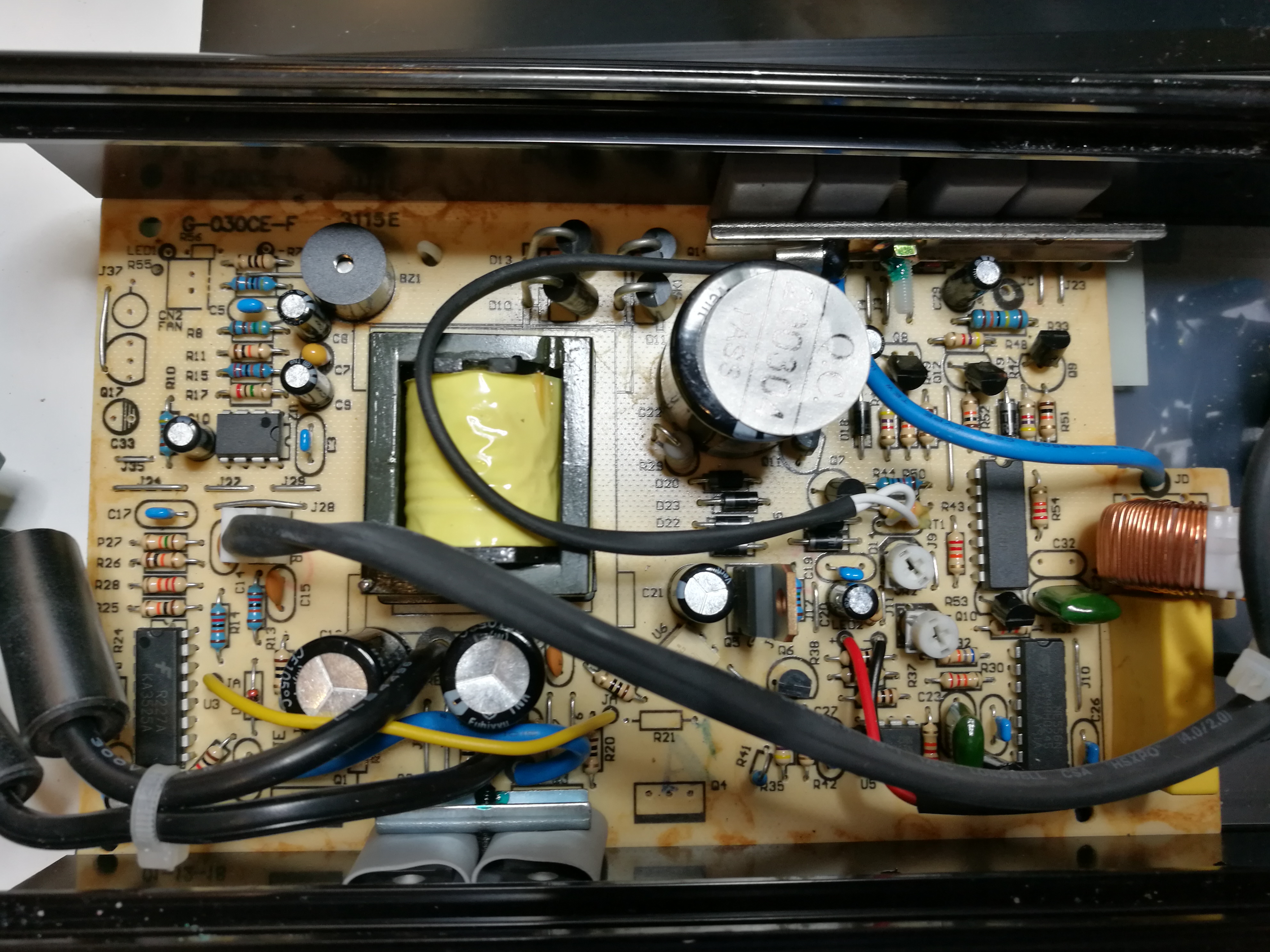
A common modified sine wave inverter topology found in consumer power inverters is as follows: An onboard microcontroller rapidly switches on and off power MOSFETs at high frequency like ~50 kHz. The MOSFETs directly pull from a low voltage DC source (such as a battery). This signal then goes through step-up transformers (generally many smaller transformers are placed in parallel to reduce the overall size of the inverter) to produce a higher voltage signal. The output of the step-up transformers then gets filtered by capacitors to produce a high voltage DC supply. Finally, this DC supply is pulsed with additional power MOSFETs by the microcontroller to produce the final modified sine wave signal. I have posted a tear-down of one modified sine wave inverter circuit to https://www.epanorama.net/blog/2017/04/19/dc-to-ac-inverter-teardown/ so yo can take a look at what a commercial product looks like.
3 Comments
Tomi Engdahl says:
“Modified sine wave” should be called “Modified square wave.” They can be very hard on some electronics. Apple printers had a reputation for dying with them, and they certainly had switching supplies.
I wouldn’t risk it. A good sine-wave inverter costs far more, but is far safer.
Tomi Engdahl says:
The devil is in the detail people. In general it will work fine unless this charger is more than 150W because then it’s likely to have power factor correction inside. This won’t like modified/square wave and might get hot or blow up all together.
Tomi Engdahl says:
Simple Modified sinewave inverter project with SG3524
https://electcommunity.com/simple-modified-sinewave-inverter-project-with-sg3524/