Venerable Ethernet provides the backbone of the internet. Ethernet has risen to complete dominance for local area networks over its forty years of existence. The first Ethernet experimentals versions started in 1972 (patented 1978). The commercialization of Ethernet started in 1980′s.
At first Ethernet technology remained primarily focused on connecting up systems within a single facility, rather than being called upon for the links between facilities, or the wider Internet. Ethernet at short distances has primarily used copper wiring. Fiber optic connections have also been available for the transmission of Ethernet over considerable distances for nearly two decades.
Today, Ethernet is everywhere. It’s evolved from a 2.93-Mb/s and then 10-Mb/s coax-based technology to one that offers multiple standards using unshielded twisted pair (UTP) and fiber-optic cable with speeds over 100 Gb/s. Ethernet, standardized by the IEEE as “802.3,” now dominates the networking world. And the quest for more variations continues onward.
Ethernet is on the Way to Total Networking Domination. Ethernet is all over the place. Most of us use it day by day. The first coax-primarily based Ethernet LAN conceived in 1973 by Bob Metcalfe and David Boggs. Since then Ethernet has grown to the stage of pretty much entire local area networking goes through it (even most WiFi hot spots are wired with Ethernet). It’s hard to overestimate the importance of Ethernet to networking over the past 25 years, during which we have seen seen Ethernet come to dominate the Networking industry. Ethernet’s future could be even more golden than its past.
Ethernet has pretty much covered office networking and backbones industrial networks. In industrial applications there applications where Ethernet is still coming. Ethernet is on the Way to Total Networking Domination article says that single-pair Ethernet makes possible cloud-to-sensor connections that enable full TCP/IP, and it’s revolutionizing factory automation. This technology will expand the use of Ethernet on the industrial applications. Several different single-pair Ethernet (SPE) standards seeks to wrap up full networking coverage by addressing the Internet of Things (IoT), and specifically the industrial Internet of Things (IIoT) and Industry 4.0 application space.
Traditional copper Ethernet
Started with 50 ohms coax in 1973. In the 1990′s the twisted pair Ethernet with RJ-45 connectors and fiber became the dominant media choices. Modern Ethernet versions use a variety of cable types.
Twisted pair Ethernet mainstream use stared with CAT 5 cable that has been long time used for 100 Mbps or slower plans, while CAT 5a cables and newer are ideal for faster speeds. Both CAT5e and CAT6 can handle speeds of up to 1000 Mbps, or a Gigabit per second.
Today, the most common copper cables are Cat5e, Cat6, and Cat6a. Now twisted pair the main media (CAT 6A, CAT7, CAT8 etc.) can handle speeds from 10M to 10G with mainstream devices, typically up to 100 meters. All those physical layers require a balanced twisted pair with an impedance of 100 Ω. Standard CAT cable has four wire pairs, and different Ethernet standards use two of them (10BASE-T, 100BASE-TX) or all four pairs (1000BASE-T and faster).
Many different modes of operations (10BASE-T half-duplex, 10BASE-T full-duplex, 100BASE-TX half-duplex, etc.) exist for Ethernet over twisted pair, and most network adapters are capable of different modes of operation. Autonegotiation is required in order to make a working 1000BASE-T connection. Ethernet over twisted-pair standards up through Gigabit Ethernet define both full-duplex and half-duplex communication. However, half-duplex operation for gigabit speed is not supported by any existing hardware.
In the past, enterprise networks used 1000BASE-T Ethernet at the access layer for 1 Gb/s connectivity over typically Cat5e or Cat6 cables. But the advent of Wi-Fi 6 (IEEE 802.11ax) wireless access points has triggered a dire need for faster uplink rates between those access points and wiring closet switches preferably using existing Cat5e or Cat6 cables. As a result, the IEEE specified a new transceiver technology under the auspices of the 802.3bz standard, which addresses these needs. The industry adopted the nickname “mGig,” or multi-Gigabit, to designate those physical-layer (PHY) devices that conform to 802.3bz (capable of 2.5 Gb/s and 5 Gb/s) and 802.3an (10 Gb/s). mGig transceivers fill a growing requirement for higher-speed networking using incumbent unshielded twisted-pair copper cabling. The proliferation of mGig transceivers, which provide Ethernet connectivity with data rates beyond 1 Gb/s over unshielded copper wires, has brought with it a new danger: interference from radio-frequency emitters that can distort and degrade data-transmission fidelity.
CAT8 can go even higher speeds up to 40G up to 30 meters. Category 8, or just Cat8, is the latest IEEE standard in copper Ethernet cable. Cat8 is the fastest Ethernet cable yet. Cat8 support of bandwidth up to 2 GHz (four times more than standard Cat6a bandwidth) and data transfer speed of up to 40 Gbps. Cat 8 cable is built using a shielded or shielded twisted pair (STP) construction where each of the wire pairs is separately shielded. Shielded foil twisted pair (S/FTP) construction includes shielding around each pair of wires within the cable to reduce near-end crosstalk (NEXT) and braiding around the group of pairs to minimize EMI/RFI line noise in crowded network installations. Cat 8 Ethernet cable is ideal for switch to switch communications in data centers and server rooms, where 25GBase‑T and 40GBase‑T networks are common. Its RJ45 ends will connect standard network equipment like switches and routers. Cat8 cable supports Power over Ethernet (PoE) technology. Cat8 is designed for a maximum range of 98 ft (30 m). If you want fater speeds and/or long distance there are various fiber interfaces.
Power over Ethernet
Power over Ethernet (PoE) offers convenience, flexibility, and enhanced management capabilities by enabling power to be delivered over the same CAT5 or higher capacity cabling as data. PoE technology is especially useful for powering IP telephones, wireless LAN access points, cameras with pan tilt and zoom (PTZ), remote Ethernet switches, embedded computers, thin clients and LCDs.
The original IEEE 802.3af-2003 PoE standard provides up to 15.4 W of DC power (minimum 44 V DC and 350 mA) supplied to each device. The IEEE standard for PoE requires Category 5 cable or higher (can operate with category 3 cable for low power levels). The updated IEEE 802.3at-2009 PoE standard also known as PoE+ or PoE plus, provides up to 25.5 W (30W) of power.
IEEE 802.3bt is the 100W Power over Ethernet (PoE) standard. IEEE 802.3bt calls for two power variants: Type 3 (60W) and Type 4 (100W). This means that you can now carry close to 100W of electricity over a single cable to power devices. IEEE 802.3bt takes advantage of all four pairs in a 4-pair cable, spreading current flow out among them. Power is transmitted along with data, and is compatible with data rates of up to 10GBASE-T.
Advocates of PoE expect PoE to become a global long term DC power cabling standard and replace a multiplicity of individual AC adapters, which cannot be easily centrally managed. Critics of this approach argue that PoE is inherently less efficient than AC power due to the lower voltage, and this is made worse by the thin conductors of Ethernet.
Cat5e cables usually run between 24 and 26 AWG, while Cat6, and Cat6A usually run between 22 and 26 AWG. When shopping for Cat5e, Cat6, or Cat6a network cables, you might notice an AWG description printed on the cable jacket such as: 28AWG, 26 AWG, or 24AWG. AWG stands for American wire gauge, a system for defining the diameter of the conductors of a wire which makes up a cable. The larger the wire gauge number, the thinner the wire and the smaller the diameter.
One of the newest types of Ethernet cables on the market, Slim Run Patch Cables, actually have a 28 AWG wire. This allows these patch cords to be at least 25% smaller in diameter, than standard Cat5e, Cat6, and Cat6a Ethernet. Smaller cable diameter is beneficial for high-density networks and data centers.
The downside of 28 AWG cable is higher resistance and power loss in PoE applications. Before February 2019, the short answer to “Can 28 AWG patch cords be used in PoE applications?” was “no.” Today, however, the answer is “yes”! 28 AWG patch cords can now be used to support power delivery.
It has been approved that 28 AWG cables can support power delivery and higher PoE levels with enough airflow around the cable. According to TSB-184-A-1, an addendum to TSB-184-A: 28 AWG patch cabling can support today’s higher PoE levels, up to 60W.
To maintain recommendations for temperature rise, 28 AWG cables must be grouped into small bundles. By keeping 28 AWG PoE patch cords in bundles of 12 or less, the impacts of cable temperature rise are diminished thus allowing you to stay within the suggested maximum temperature rise of 15 degrees Celsius. Per TSB-184-A-1, an addendum to TSB-184-A: 28 AWG in bundles of up to 12 can be used for PoE applications up to 30W.In PoE applications using between 30W and 60W of power, spacing of 1.5 inches between bundles of 12 cables is recommended. Anything above 60W with 28 AWG cable requires authorization from the authority in USA.
Single pair Ethernet
Several different single-pair Ethernet (SPE) standards seeks to wrap up full networking coverage by addressing the Internet of Things (IoT), and specifically the industrial Internet of Things (IIoT) and Industry 4.0 application space.
Single Pair Ethernet, or SPE, is the use of two copper wires that can transmit data at speeds of up to 1 Gb/s over short distances. In addition to data transfer, SPE has option to simultaneously delivering Power over Dataline (PoDl). This could be a major step forward in factory automation, building automation, the rise of smart cars, and railways. Single-pair Ethernet (SPE) allows legacy industrial networks to migrate to Ethernet network technology whilst delivering power and data to and from edge devices.
Traditional computer-oriented Ethernet comes normally in two and four-pair variants. Different variants of Ethernet are the most common industrial link protocols. Until now, they have required 4 or 8 wires, but the SPE link is allows using only two wire pairs. Using only two wire pairs can simplify the wiring and can allow reusing some old industrial wiring for Ethernet application. SPE offers additional benefits such as lighter and more flexible cables. Their space requirements and assembly costs are lower than with traditional Ethernet wiring. Those are the reasons why the technology is of interest to many.
The 10BASE-T1, 100BASE-T1 and 1000BASE-T1 single-pair Ethernet physical layers are intended for industrial and automotive applications or as optional data channels in other interconnect applications.
Automotive Ethernet, called 802.3bw or 100BASE-T1, that adapts Ethernet to the hostile automotive environment with a single pair.
There is also a long distance 10BASE-T1L standard that can support distance up to one one kilometer at 10-Mb/s speed. In building automation, long reach is often needed for HVAC, fire safety, and equipment like elevators. The 10BASE-T1 standard has two parts. The main offering is 10BASE-T1L, or long reach to 1 km. The connection is point-to-point (p2p) with full-duplex capability. The other is 10BASE-T1S, or short-reach option that provides p2p half-duplex coverage to 25 meters and includes multidrop possibilities.
All those physical layers require a balanced twisted pair with an impedance of 100 Ω. The cable must be capable of transmitting 600 MHz for 1000BASE-T1 and 66 MHz for 100BASE-T1.
Single-pair Ethernet defines its own connectors:
- IEC 63171-1 “LC”: This is a 2-pin connector with a similar locking tab to the modular connector, if thicker.
- IEC 63171-6 “industrial”: This standard defines 5 2-pin connectors that differ in their locking mechanisms and one 4-pin connector with dedicated pins for power. The locking mechanisms range from a metal locking tab to M8 and M12 connectors with screw or push-pull locking. The 4-pin connector is only defined with M8 screw locking.
Fiber Ethernet
When most people think of an Ethernet cable, they probably imagine a copper cable, and that’s because they’ve been around the longest. A more modern take on the Ethernet cable is fiber optic. Instead of depending on electrical currents, fiber optic cables send signals using beams of light, which is much faster. In fact, fiber optic cables can support modern 10Gbps networks with ease. Fiber optic has been option on Ethernet for a long time. Ethernet has been using optical fiber for decades. The first standard was 10 Mbit/s FOIRL in 1987. The currently fastest PHYs run 400 Gbit/s. 800 Gbit/s and 1.6 Tbit/s started development in 2021.
The advantage most often cited for fiber optic cabling – and for very good reason – is bandwidth. Fiber optic Ethernets can easily handle the demands of today’s advanced 10 Gbps networks or 100Gbps, and have the capability of doing much more. Fiber optic cables can run without significant signal loss for distances, from kilometers up to tens of kilometers depending on the fiber type and equipment used.
The cost of fiber has come down drastically in recent years. Fiber optic cable is usually still a little more expensive than copper, but when you factor in everything else involved in installing a network the prices are roughly comparable.
Fiber optics is immune to the electrical interference problems because fiber optic cable doesn’t carry electricity, it carries light. Because fiber optic cables don’t depend on electricity, they’re less susceptible to interference from other devices.
Fiber optic cables are sometimes advertised to be more secure than copper cables because light signals are more difficult to hack. It is true that light signals are slightly more difficult to hack than copper cable signals, but actually they are nowadays well hackable with right tools.
Fiber has won the battle in the backbone networks on long connections, but there is still place for copper on shorter distances Nearly every computer and laptop sold today has a NIC card with a built-in port ready to accept a UTP copper cable, while a potentially expensive converter or fiber card is required to make a fiber optic cable connection.
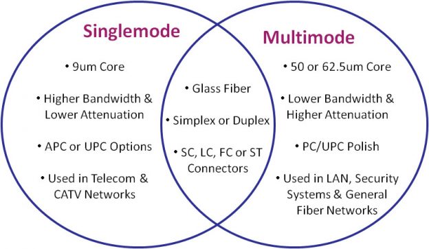
Standard fiber-optic cables have a glass quartz core and cladding. Nowadays, there are two fiber optic cable types widely adopted in the field of data transfer—single mode fiber optic cable and multimode fiber optic cable.
A single-mode optical fiber is a fiber that has a small core, and only allows one mode of light to propagate at a time. So it is generally adapted to high speed, long-distance applications. The core size of single mode fiber has a core diameter between 8 and 10.5 micrometers with and a cladding diameter of 125 micrometers. OS1 and OS2 are standard single-mode optical fiber used with wavelengths 1310 nm and 1550 nm (size 9/125 µm) with a maximum attenuation of 1 dB/km (OS1) and 0.4 dB/km (OS2). SMF is used in long-haul applications with transmission distances of up to 100 km without need a repeater. Typical transmission distances are up 10-40 kilometers. Single mode capable hardware used to be very expensive years ago, but prices for then have came down quicly. Nowadays single mode is very commonly uses.
Multimode optical fiber is a type of optical fiber with a larger core diameter larger (65 or 50 micrometer core) designed to carry multiple light rays, or modes at the same time. It is mostly used for communication over short distances. Multimode Fiber (MMF) uses a core/cladding diameter of typically 50 micrometer/125 mictometer, providing less reach, up to approximately 2 km or less, due to increased dispersion as a result of the larger diameter core.
Depending on your requirements, when going to use fiber, you’re probably first looking for one of these commonly used interfaces: 1000BASE-SX (1 Gbit/s over up to 550 m of OM2 multi-mode fiber), 1000BASE-LX (1 Gbit/s over up to 10 km of single-mode fiber), 10GBASE-SR (10 Gbit/s over up to 400 m of OM4 MMF), 10GBASE-LR (10 Gbit/s over up to 10 km of SMF).
There are many other PHY standards for various data rates and distances, also many common non-standards for even longer distance. The required optical transceivers are usually SFP (1G) or SFP+ modules (10G) plugged into your network hardware. Switches and network adapters with SFP modules allow you to create custom fiber optic high-speed Ethernet networks by plugging in suitable type SFP module. External media converters for devices without SFP slot are also available. A fiber media converter, also known as a fiber to Ethernet converter, allows you to convert typical copper Ethernet cable (e.g., Cat 6a) to fiber and back again.
100G (100 Gb/s) Ethernet has had a good run as the backbone technology behind the cloud, but the industry is moving on. There is expected to be exploding demand for bandwidth in the 5G/mmWave era that’s now upon us. Modern
400G and 800G test platforms validate the cloud’s Ethernet backbone, ensuring support for the massive capacity demands of today and tomorrow. Many service providers and data centers, for various reasons, skipped over 400G Ethernet implementations and are looking toward 800G Ethernet for their next network transport overhaul. Adoption of 400G is still happening, but the growth of 800G will eclipse it before long.
In the future, the speeds of Ethernet networks will increase. Even after the 25, 40, 50 and 100 gigabit versions, more momentum is needed. For example, growing traffic in data centers would require 100G or even faster connections over long distances. Regardless of future speed needs, 200G or 400G speeds are best suited for short-term needs. The large cloud data centers on the Internet have moved to 100GbE, 200GbE and 400G solutions for trunk connections. They also require strong encryption and, in addition, accurate time synchronization of the backbone networks of 5G networks. Media Access Control security (MACsec) provides point-to-point security on Ethernet links. MACsec is defined by IEEE standard 802.1AE. IEEE 802.1X is an IEEE Standard for port-based Network Access Control (PNAC).
High-speed terabit rates do not yet make sense to implement now. The standardization organization OIF (Optical Interworking Forum) has worked up to 800 gigabit connection speeds. The Ethernet Technology Consortium proposed an 800 Gbit/s Ethernet PCS variant based on tightly bundled 400GBASE-R in April 2020. In December 2021, IEEE started the P802.3df Task Force to define variants for 800 and 1600 Gbit/s over twinaxial copper, electrical backplanes, single-mode and multi-mode optical fiber along with new 200 and 400 Gbit/s variants using 100 and 200 Gbit/s lanes. Lightwave magazine expects that 800G Ethernet transceivers become most popular module in mega data centers by 2025. There are already test instruments designed to validate 1.6T designs.
There is also one fiber tpye I have not mentioned yet. Plastic optical fiber (POF) has emerged as a low cost alternative to twisted pair copper cabling and coaxial cables in office, home and automotive networks. POF technology offers an attractive alternative to traditional glass optical fiber as well as copper for industrial, office, home and automotive networks. POF typically utilizes a polymethylmethacrylate (PMMA) core and a fluoropolymer cladding. Glass fiber-optic cable offers lower attenuation than its plastic counterpart, but POF provides a more rugged cable, capable of withstanding a tighter bend radius.
POF has generally been utilized in more niche applications where its advantages outweigh the need for high bandwidth and relatively short maximum distance (only tens of meters). Currently in the market, several manufacturers have developed fiber optic transceivers for 100Mbps Ethernet over plastic optical fiber and there exist also 1Gbit/s versions. Advances in LED technology and Vertical Cavity Surface Emitting Laser (VCSEL) technology are enabling POF to support data rates of 3Gbps and above
POF offers many benefits to the user: it is lightweight, robust, cheap and easy to install; the use of 650nm red LED light makes it completely safe and easier to diagnose as red light can be seen by the human eye. There are several different connectors used for PoF. There is also connector-less option called Optolock, where you can simply slice the plastic fiber with a knife, separate the fibers, insert the fiber into the housing and then lock it in place.
Industrial networks special demands for Ethernet
Industrial networks need to be durable. Industrial applications on the field needs often more durable connectors than the traditional RJ-45 connector of office networks.
Here is a list of some commonly used industrial Ethernet connector types:
- 8P8C modular connector: For stationary uses in controlled environments, from homes to datacenters, this is the dominant connector. Its fragile locking tab otherwise limits its suitability and durability. Bandwidths supporting up to Cat 8 cabling are defined for this connector format.
- M12X: This is the M12 connector designated for Ethernet, standardized as IEC 61076-2-109. It is a 12mm metal screw that houses 4 shielded pairs of pins. Nominal bandwidth is 500MHz (Cat 6A). The connector family is used in chemically and mechanically harsh environments such as factory automation and transportation. Its size is similar to the modular connector.
- ix Industrial: This connector is designed to be small yet strong. It has 10 pins and a different locking mechanism than the modular connector. Standardized as IEC 61076-3-124, its nominal bandwidth is 500MHz (Cat 6A).
In addition to those there are applications that use other versions of M12 and smaller M8 connectors.
Current industrial trends like Industrie 4.0 and the Industrial Internet of Things lead to an increase in network traffic in ever-growing converged networks. Many industrial applications need reliable and low latency communications. Many industries require deterministic Ethernet, and Industrial Automation is one of them. The automation industry has continuously sought solutions to achieve fast, deterministic, and robust communication. Currently, several specialized solutions are available for this purpose, such as PROFINET IRT, Sercos III, and Varan. TSN can help standardize real-time Ethernet across the industry.
TSN refers to a set of IEEE 802 standards that make Ethernet deterministic by default. TSN is an upcoming new technology that sits on Layer 2 of the ISO/OSI Model. It adds definitions to guarantee determinism and throughput in Ethernet networks. It will provide standardized mechanisms for the concurrent use of deterministic and non-deterministic communication. AVB/TSN can handle rate-constrained traffic, where each stream has a bandwidth limit defined by minimum inter-frame intervals and maximal frame size, and time-trigger traffic with an exact accurate time to be sent. Low-priority traffic is passed on best-effort base, with no timing and delivery guarantees. Time-sensitive traffic has several priority classes.
Time-Sensitive Networking (TSN) is a set of standards under development by the Time-Sensitive Networking task group of the IEEE 802.1 working group. The majority of projects define extensions to the IEEE 802.1Q – Bridges and Bridged Networks, which describes Virtual LANs and network switches. These extensions in particular address the transmission of very low transmission latency and high availability. Applications include converged networks with real-time Audio/Video Streaming and real-time control streams which are used in automotive or industrial control facilities.
In contrast to standard Ethernet according to IEEE 802.3 and Ethernet bridging according to IEEE 802.1Q, time is very important in TSN networks. For real-time communication with hard, non-negotiable time boundaries for end-to-end transmission latencies, all devices in this network need to have a common time reference and therefore, need to synchronize their clocks among each other. This is not only true for the end devices of a communication stream, such as an industrial controller and a manufacturing robot, but also true for network components, such as Ethernet switches. Only through synchronized clocks, it is possible for all network devices to operate in unison and execute the required operation at exactly the required point in time. Scheduling and traffic shaping allows for the coexistence of different traffic classes with different priorities on the same network.
The following are some of the IEEE standards that make up TSN:
Enhanced synchronization behavior (IEEE 802.1AS)
Suspending (preemption) of long frames (IEEE 802.1-2018)
Enhancements for scheduled traffic (IEEE 802.1Q-2018)
Path control and bandwidth reservation (IEEE 802.1Q-2018)
Seamless redundancy (IEEE 802.1CB)
Stream reservation (IEEE 802.1Q-2018)
Synchronization of clocks across the network is standardized in Time-Sensitive Networking (TSN). Time in TSN networks is usually distributed from one central time source directly through the network itself using the IEEE 1588 Precision Time Protocol, which utilizes Ethernet frames to distribute time synchronization information.
261 Comments
Tomi Engdahl says:
https://www.lapp.com/en_US/us/service/download-area/whitepaper/exploring-the-role-and-development-category-cables/e/001952
Tomi Engdahl says:
https://www.panduit.com/content/dam/panduit/en/solutions/solution-pdf/ICTToday_AVoverIP.pdf
1 GbE Versus 10 GbE—The Debate
There is an ongoing debate in the industry about whether
a 1 Gb/s or 10 Gb/s architecture provides the ideal net-
work topology for AV systems. The discussion often gets
mixed between infrastructure and AVoIP applications. For
the cabling infrastructure, cables that can carry 10 Gb/s
signals are advised, especially for new structures and
buildings to future proof the networks either inside
the data center or from remote customer premises
equipment (CPE).
When the structure is wired with 10 Gb/s Cat 6A-
capable cabling, an AVoIP application can be addressed.
What type of AVoIP solutions should be used to move
video and audio on the network? To answer this ques-
tion, it is vital to understand the benefits of using 1 GbE
versus 10 GbE AVoIP solutions.
1 GbE—The Incumbent
Installing and operating AVoIP encoders and decoders
that are 1 GbE capable means that network devices (e.g.,
L2/L3 switchers) do not need to support 10 GbE; they can
be limited to 1 GbE. At this point, the network becomes
1 GbE, and this solution delivers many features and bene-
fits that will keep it viable for years to come. One benefit
is the cost of the network; 1 GbE network switches are far
more cost-friendly and offer a capital expense advantage
for companies. There are many 1 GbE network switches
available. They provide the buyer with a good selection
and the ability to choose one that fits both the budget
and network specification requirements.
Another strong advantage of AVoIP network devices
that run video traffic at 1 Gb/s over a 1 GbE network
is the ability to run the signal over a longer distance.
Data traffic that runs at a rate of 10 Gb/s over a 10 GbE
network is more susceptible to electromagnetic interfer-
ence (EMI) and radio frequency (RF) noise and runs
at shorter distances. This can be a strong limiting factor
when trying to run high-resolution video, such as ultra-
high-definition (UHD) 4K/UHD at 60 frames-per-second.
When copper cabling is used as the cabling infrastruc-
ture, 1GbE network infrastructure devices benefit from
the availability, cost effectiveness and maturity of Power
over Ethernet (PoE) technology.
The main disadvantage of 1 GbE networks is that
they are bit rate constrained. A 1 GbE network actually
runs a net bit rate (removing IP headers and other layers
of signaling and protocols, and using regular frames)
of around 900 Mb/s. This represents the amount of bit
rate available to work with versus the approximate 9000
Mb/s in 10 GbE networks. This is not always a limitation
but is something to be aware of when weighing the pros
and cons of one versus the other.
10 GbE – The Need for Speed
High-resolution video consumes large amounts of data.
For example, high-definition (HD) 1920 x 1080 resolution
images running at 60 frames-per-second can consume
up to 4.46 Gb/s while UHD video at 3840 x 2160 resolu-
tion at 60 frames-per-second can consume up to 17.82
Gb/s. A 10 GbE network can pass HD video without video
compression. Unlike 1 GbE-based AVoIP systems where
video is always compressed in order to fit into the narrow
bandwidth of 900 Mb/s, a 10 GbE AVoIP-based system
often does not require compression in the case of HD
video. When compression is required for UHD, the
amount of compression required is very low, which
is the most significant advantage of 10 GbE AVoIP
systems; the amount of compression applied on video
is minimal, if required at all.
Simply put, when comparing the video quality
of the streamed video with uncompressed video, it is bit-
to-bit identical to the source. What the source produces
is exactly what the display will show. Yes, some compres-
sion is needed for UHD signals that can climb to 17.82
Gb/s, but the compression is very light versus compress-
ing the same signal onto a 1 GbE network.
This 10 GbE advantage may steer designers and
installers away from 1 GbE networks. After all, who wants
low video quality images running in meeting spaces or
lecture/study halls? However, advances in compression
algorithms and increases in computing power have
resulted in impressive video quality to a degree of visu-
ally lossless even when compressed to work in a 1 GbE
pipeline. In other words, today’s AVoIP encoders and
decoders use advanced compression technology that
makes it difficult to distinguish between the source and
the compressed image when placing them side-by-side.
For AV purposes, this means that a 1 GbE network can
be sufficient.
A 10 GbE AV network requires little to no compres-
sion but uses the entire 10 Gb/s bandwidth provided
by the network. The same 10 GbE network can accom-
modate 1 GbE AVoIP alongside existing enterprise net-
work traffic with ease, thereby eliminating the need for
a dedicated 10 GbE AV network
Although there are a variety of different network
topologies, AVoIP encoder and decoder devices will nearly
always be connected to one of three groups: single logical
switch, star or fat tree. Each of these topologies has its
own distinct advantages and disadvantages:
Single Logical Switch
By far, the simplest network topology is one that uses
a single switch (Figure 1). In this type of system, each
device is connected to a single logical switch that is not
connected to any other switches or routers.
Advantages: Simple, easy to manage, limited network
impact of video traffic, inexpensive.
Disadvantages: Limited scalability options, no network
redundancy, single point of failure.
Star
For systems needing more scalability than that offered
by a single logical switch, multiple logical switches can
be each connected to a single switch for intercommunica-
tion. In this star topology (Figure 2), the central switch
is often referred to as a “core” switch; the other switches
are referred to as “access” switches. This type of system
will typically have AVoIP encoders and decoders
connected to the access switches.
Advantages: Scalability, multiple access switches can
create network path redundancy.
Disadvantages: Physical network layout can make cabling
very expensive, since all access switches must be directly
connected to the core; single core switch creates a single
point of failure.
Fat Tree
Very large network systems often fall into the category
of a fat tree topology (Figure 3). Here, access switches are
connected to a distribution switch in a way that resem-
bles a star network. Multiple distribution switches are
connected to a core switch. There can be multiple layers
of distribution switches, and multiple core switches can
be interconnected. Links further up the tree (closer
to core switches) are “fatter” or higher bandwidth than
links further down the tree (closer to access switches).
Advantages: Ultimate scalability, potential for high
network path redundancy (protections when specific
path is down due to switch failure).
Disadvantages: Management complexity, cost.
Switch Fabric
No matter which of the network segregation methods
is chosen, the switch fabric’s non-blocking bandwidth
specification is a key consideration. The network switches
must have enough switch fabric bandwidth to support
full non-blocking bidirectional gigabit bandwidth on all
ports simultaneously. Information technology and AV
administrators need to be mindful that when working
with network switches that have downlink ports in the
switch (i.e., ports that are connected to AV over IP encod-
ers and decoders), physical line bandwidth may specify
1 GbE ports. However, the switch capacity to handle IP
traffic (i.e., the actual bit and bytes of data) is lower than
total downlink ports multiplied by connected active 1 GbE
AVoIP devices. This creates a blocking architecture.
Low-latency, high-fidelity AVoIP networks are
“connectionless,” meaning that there is no feedback
coming from the receiving end to indicate packet loss.
This makes lower latency streaming over the network
possible, but a genuine challenge arises collectively.
What happens when packets get lost or arrive in the
wrong order? What mechanism can be used to still bene-
fit from the connectionless protocol layer and protect
traffic, as much as possible, from arrival order issues and
packet loss? This is where forward error correction (FEC)
technology becomes critical.
IP data packets are susceptible to packet drops, packet
losses and packet arrival order misalignment as the facili-
ty’s network scales, more network nodes are added, and
traffic load increases.
Error Correction
To fix errors and loss packets, the AV/IT administrator
or system integrator needs to measure error rates. Software
tools that measure error rates are available, as are dedicated
hardware appliances that can run traffic in and out and
measure packet loss statistics over time.
Once the error rate and level are identified, the next
step is to activate and configure the FEC mechanism.
Audiovisual, IT administrators and systems integra-
tors are strongly advised to choose AVoIP encoder and
decoder devices that support FEC mechanisms. An FEC-
enabled encoder places video packets in an internal vir-
tual table with L columns and D rows. The packets are
aligned in columns and rows with a mathematical XOR
calculation for each row and for each column
In case of packet loss, the reverse XOR operation
(XNOR) is used to calculate back the missing packet.
It is important to note that activating and using FEC
will result in generating additional data packets that are
not part of the audio or video data stream. The FEC
packets are additional traffic that will consume bit rate,
and this needs to be considered when planning and allo-
cating bit rate for video and audio
The AVoIP traffic is delay-sensitive. As such, the
traffic must be prioritized when arriving to a network
switch. In the networking world, standardized protocols
are used to implement policies. One of the protocols
that is used to configure the network elements to clas-
sify traffic is differentiated service (DiffServ). In a nut-
shell, each data type will be assigned a differentiated
service code point (DSCP) for classification. The DSCP
value is assigned to each packet at the encoder, and it
is mapped against five main precedence values: best
effort, low, normal, high and highest.
For networks that run AVoIP services in conjunction
with other types of data, it is highly advised to prioritize
AVoIP-related protocols (i.e., multicast and IGMP) over
non-delay critical data. For highly congested network
Latency
Audiovisual over IP is used to deliver content and infor-
mation to the audience that may be located in the same
room as the content source or in other places within the
enterprise. In cases when the audience is in the same
room, such as a study hall, meeting space or conference
room, the tolerance for delay or latency is very low. On
the other hand, when the content source and audience
are in different locations, the tolerance for latency
is higher and less strict.
Audiovisual over IP systems will introduce latency,
mainly because of the video and audio processing that
takes place within the devices. Some AVoIP devices will
consume more time to process video and audio and oth-
ers will require less. It is imperative to ensure that when
AVoIP is installed, the minimum latency available
is introduced.
It is recommended that systems inte-
grators who install AVoIP introduce less than 10 ms
latency when the encoder and decoder are connected
back-to-back.
Security
Network security is among the top priorities for an AVoIP
installation or network device. Devices require security
protocols around authentication and authorization. There
are instances where rogue machines are plugged into
a university network, for example, disguised as a legiti-
mate element of the network. Proper authentication
and authorization protocols prevent unlawful monitor-
ing of traffic and theft of content and information.
Security protocols, such as IEEE 802.1x, are ideal for
implementation on network devices. Utilizing the IEEE
802.1x protocol on AVoIP networks enables the provision
(e.g., assigning IP address, sending configuration) to take
place only to authenticated devices and prevents rogue
elements from disguising themselves as an encoder
or decoder to gain access. Management protocols from
control and network monitoring devices must also be
secured for the same reasons.
All devices on the AVoIP network must also be
immune to outside attacks and be able to fend off rogue
attempts to access the network through device usernames
and passwords. These attacks typically happen swiftly, and
proper security protocols provide the appropriate level
of access control and network protection
Audiovisual over IP devices are tasked to stream and
receive video and audio media over IP networks. Unlike
other distribution technologies (e.g., circuit-based distri-
bution), IP packets are susceptible to being hacked. Add-
ing a layer of encryption to the content protects the ser-
vice from being hacked and ensures that only devices able
to decipher the content can decode and display the con-
tent. One leading technology that is used for this is the
advanced encryption standard (AES), and it is advised
to use AVoIP devices that support at least 128-bit AES.
Tomi Engdahl says:
https://www.lapp.com/en_US/us/service/download-area/whitepaper/exploring-the-role-and-development-category-cables/e/001952
https://www.lapp.com/en_US/us/products/cable-glands/c/113980
Tomi Engdahl says:
A GUIDE TO SINGLE PAIR ETHERNET (SPE)
https://www.lapp.com/en_US/us/service/download-area/whitepaper/guide-to-single-pair-ethernet/e/001012
Tomi Engdahl says:
https://www.makeuseof.com/cat-5e-wiring-diagram/
Tomi Engdahl says:
https://www.uusiteknologia.fi/2023/08/23/nopea-gigabitin-kytkinpiiri-teollisuuteen/
Tomi Engdahl says:
https://etn.fi/index.php/13-news/15232-10-megabitin-ethernet-tulossa-autoihin
Tomi Engdahl says:
Supper mini FTTH 1 Pair Gigabit Fiber Optical Media Converter 10/100/1000Mbps Single Mode Single Fiber SC
https://www.aliexpress.com/item/32993728821.html
Tomi Engdahl says:
https://etn.fi/index.php/new-products/15239-uusi-ethernet-kytkin-muokkaa-kehyksiae-lennossa
Tomi Engdahl says:
Ethernet-APL: Optimization of Process Automation with Actionable Insights
https://www.analog.com/en/thought-leadership/ethernet-apl-optimization-of-process-automation.html
Ethernet-APL (advanced physical layer) specifies the details of the application of Ethernet communication to sensors and actuators for the process industry and will be published under the IEC. It is based on the new 10BASE-T1L (IEEE802.3cg-2019) Ethernet physical layer standard, approved on November 7, 2019, and specifies the implementation and explosion protection methods for use in hazardous locations. The leading companies in process automation are working together under the umbrella of PROFIBUS and PROFINET International (PI), ODVA, Inc., and FieldComm Group® to make Ethernet-APL work across Industrial Ethernet protocols and to accelerate its deployment.
Why is Ethernet-APL important? Ethernet-APL will change the process automation world by enabling high bandwidth, seamless Ethernet connectivity to field devices. It solves the challenges that, to date, have limited the use of Ethernet to the field. These challenges include power, bandwidth, cabling, distance, and use in hazardous locations. By solving these challenges for both brownfield upgrades and new greenfield installations, Ethernet-APL will enable new insights that were previously unavailable, such as combining process variables, secondary parameters, and asset health feedback and seamlessly communicating them to the control layer. These new insights will awaken new possibilities for data analysis, operational insights, and productivity improvements through a converged Ethernet network from the field to the cloud (see Figure 1).
Tomi Engdahl says:
There is now a quite recent standard 10BASE-T1L that is capable of running 10 megabits up to one kilometer. It is gathering interest in industrial automation applications like this
https://www.analog.com/en/technical-articles/the-new-10base-t1l-standard.html
Tomi Engdahl says:
https://www.commscope.com/globalassets/digizuite/2164-category-6a-the-cabling-of-choice-for-new-installations-wp-112053-en.pdf?utm_source=blog&utm_medium=socialmedia&utm_campaign=blogging&r=1
Tomi Engdahl says:
https://www.commscope.com/insights/the-enterprise-source/power-over-ethernet-and-your-networks-future/
Tomi Engdahl says:
https://interactive.commscope.com/category-choosing-tool/p/1
Tomi Engdahl says:
https://www.commscope.com/globalassets/digizuite/712076-400g-and-beyond-eb-114804-en.pdf
The migration to 400G/800G: Part I
https://www.commscope.com/insights/the-enterprise-source/migration-to-400g800g-the-fact-file-part-1/
The migration to 400G/800G: Part II
https://www.commscope.com/insights/the-enterprise-source/migration-to-400g800g-the-fact-file-part-2/
Tomi Engdahl says:
Factory automation design made simple with multiprotocol industrial Ethernet systems
https://e2e.ti.com/blogs_/b/industrial_strength/posts/factory-automation-design-made-simple-with-multiprotocol-industrial-ethernet-systems?HQS=null-null-conbr-confactory_factory-asset-ta-electronicdesign_psfi_connect_l2-wwe_int&DCM=yes&dclid=CM-Nk9m4u4EDFTTbOwIdm74EdQ
Factory automation equipment – sensors, actuators, drives and programmable logic controllers (PLCs) – supports industrial Ethernet protocols such as EtherCAT, Profinet, EtherNet Industrial Protocol (EtherNet/IP) and Sercos, each one exchangeable by loading a different software image onto the hardware platform.
Multiprotocol industrial Ethernet systems reduce manufacturing costs in the hardware development cycle, reducing bill-of-materials costs by requiring fabrication of only a single printed circuit board, thereby accelerating time to market. Manufacturers can offer field devices such as digital input modules or servo drives for factory automation using different industrial Ethernet protocols.
Architectures such as TI’s programmable real-time unit industrial communications subsystem (PRU-ICSS) can support industrial Ethernet speeds of 1,000 Mbps for field devices – especially with the new Time-Sensitive Networking (TSN) protocol.
Tomi Engdahl says:
LTC4296-1/LTC9111 SPoE/PD Controllers
https://www.digikey.com/en/product-highlight/a/analog-devices/ltc4296-1-ltc9111-spoe-pd-controllers?dclid=CMmn5MCFu4EDFRPwGQod4y8Cgw
Analog Devices’ LTC4296-1 and LTC9111 are IEEE 802.3cg-compliant controllers
Image of Analog Devices’ LTC4296-1/LTC9111 SPoE/PD ControllersADI’s LTC4296-1 is an IEEE 802.3cg-compliant, five port, Single-Pair Power over Ethernet (SPoE), PSE controller. SPoE simplifies system design and installation with standardized power and Ethernet data over a single-pair cable. It is designed for interoperability with 802.3cg PDs in 24 V or 54 V systems. The LTC4296-1 delivers power using external, low drain-to-source on-resistance (RDS(ON)), N-channel metal-oxide semiconductor field-effect transistors (MOSFETs), which minimize voltage drop and ensure application ruggedness.
Tomi Engdahl says:
EDGE8® Solutions Make the Future Accessible
https://www.corning.com/data-center/worldwide/en/home/solutions/edge8.html?utm_source=Personifi&utm_medium=advertising&utm_content=edge8&utm_campaign=dc-private
From the engineering to IT, to the facilities management to the end user experience, EDGE8® is the future of data centers. Enjoy the future-forward Base-8 design, expanded portfolio of specialty modules for enhanced security and networking, all scaled off your current EDGE architecture!
EDGE8 has improved technology adoption, due to the 100% fiber utilization without the need for the conversion modules. This leads to cost and loss savings, in addition to risk avoidance – providing a simple path to 40G, 100G, and even 400G.
Over 50 million EDGE fiber terminations successfully deployed since 2009!
EDGE™ Solutions – Commit to THE Platform with THE demonstrated record of success
https://www.corning.com/data-center/worldwide/en/home/solutions/edge.html?utm_source=Personifi&utm_medium=advertising&utm_content=edge&utm_campaign=dc-private
Corning’s unwavering commitment to the EDGE Platform for over a decade has driven the Private Data Center industry forward. Evolving from lower density legacy hardware solutions, to high density Data Center optimized solutions prevalent in the market today. Available in Clearcurve OM3, OM4 and Single-Mode, EDGE simplifies MTP-based structured cabling to ensure networks have an optimized migration path as networks grow from 10G to 100G, to 400G and beyond.
EDGE constantly innovates new preterminated solutions that offer high deployment speeds, sustainability, and labor-saving benefits, making it easier for Data Centers to meet the high-density demands of the modern network. Our products consider the total cost of ownership, and provide peace of mind for the physical infrastructure, mitigating risk and keeping your network secure with easy-to-use pre-connectorized EDGE components.
Tomi Engdahl says:
Tap Modules
https://www.corning.com/data-center/worldwide/en/home/products/tap-module.html?utm_source=Personifi&utm_medium=advertising&utm_content=Tap-Module&utm_campaign=dc-private
Why choose EDGE™ or EDGE8® Tap Modules for your network? EDGE and EDGE8 Tap Modules enable passive optical tapping of the network while reducing downtime and link loss, and increasing rack space utilization and density. Unlike other passive optical Tap solutions that must be added as separate layers in the network link, Corning Tap Modules allow network monitored ports to be added without disrupting the system’s live traffic. Insertion loss in the link is reduced by integrating the passive optical tapping into the module. Infrastructure flexibility, speed of deployment, and network uptime are just a few of the benefits offered by our advanced, integrated design.
Tomi Engdahl says:
Hyperscale Data Installation Race
A side-by-side comparison of preterminated and spliced fiber optic cabling solutions
https://www.corning.com/data-center/worldwide/en/home/knowledge-center/hyperscale-data-center-installation-race.html?utm_source=Personifi&utm_medium=Advertising&utm_content=edge-rapid-connect-case-study&utm_campaign=dc-h4
A facility that’s future-ready will offer scalability, flexibility, modularity, and stringent service-level agreements.
https://www.corning.com/data-center/worldwide/en/home/knowledge-center/hyperscale-data-center-installation-race.html?utm_source=Personifi&utm_medium=Advertising&utm_content=edge-rapid-connect-case-study&utm_campaign=dc-h4
What is a multitenant data center?
A multitenant data center (MTDC), also known as a colocation data center, is a facility where organizations can rent space to host their data. MTDCs provide the space and networking equipment to connect an organization to service providers at a minimal cost. Businesses can rent to meet varying needs—from a server rack to a complete purpose-built module. The scalability of usage provides the business benefits of a data center without the high price.
What are the challenges and benefits involved?
Reliability is critical. The key challenge is to ensure that the MTDC will allow you to access data quickly and at a moment’s notice—it is no easy task to deliver seamless bandwidth capacity for every provision.
Examples of overcoming this challenge can be found across the globe. For example, Pier DC is a Tier III certified MTDC in Western Australia. Tier III certification requires 100-percent uptime and multiple distribution paths to allow for no downtime for maintenance, repair, or replacement of equipment. To meet this, Pier DC deployed an all-optical- fiber cabling infrastructure. The high-density preterminated optical solution supports integrated control systems as well as passive optical cabling for customer crossconnects. This enabled Pier DC to provide their customers with the assurance that they will have access to their entrusted data and services at all times, regardless of demand spikes, capacity requirements, and moves, adds, and changes (MACs) that occur during the lifetime of any data center.
A major benefit that makes the investment worthwhile is the longevity of data centers. More and more organizations are looking to outsource their data storage and services. In fact, spend on outsourcing to MTDCs is expected to double by 2022, increasing the current amount of $31.5 billion to $60 billion. As data continues to explode, it continues to be imperative that every data center meets future capacity requirements—and fast.
For many businesses, outsourcing to an MTDC facility is important for even more specific reasons.
Accessing rapid deployment for low and high-density applications
Leveraging the assurance of stringent service-level agreements (SLAs)
Scaling quickly to meet higher-speed technologies and applications
Sourcing maximum flexibility to assure future-readiness
Reducing total cost of ownership (TCO)
MTDCs are focused on enabling rapid connections for their customers and providing offerings to meet a range of business, enterprise, and cloud needs. Because of this focus, operators typically undertake a hardware and technology refresh at least every three years. This refresh, combined with the anticipated 10-year lifespan of a data center, is a major business saver in capital expenditure, time, and resources.
Tomi Engdahl says:
A GUIDE TO SINGLE PAIR ETHERNET (SPE)
https://www.lapp.com/en_US/us/service/download-area/whitepaper/guide-to-single-pair-ethernet/e/001012
1. SINGLE PAIR ETHERNET (SPE): THE FUTURE OF IIOT
Plants, machines, controls, actuators, sensors and even tools and workpieces: in the factory of the future, everything is connected to everything – including the Internet and the cloud – every physical object has a virtual image.
So far, though, the industrial Internet of Things has experienced a system discontinuity: while Ethernet has long been established as the communication standard at the control level of the automation pyramid, other standards dominate at the lower level, the field level. Fieldbus systems prevail where sensors and actuators are networked. Some components often still transmit information in analogue mode. But as the promises of Industry 4.0 become reality, seamless communication across all levels is essential – the field level cannot remain an island of technology. This requires new infrastructure at field level. It must meet several prerequisites. First, it must be compatible with the Ethernet networks above it. Also, at the same time, it should be cost-effective and space-saving, as space is tight in many machines.
2. HISTORY AND MOTIVATION BEHIND SPE
The origins of Ethernet go back to the 1970s. It was originally developed for fast communication between office computers and data centres, and efforts have been made for nearly 20 years to establish Ethernet in industrial production. This has many advantages:
IT data and real-time data are transferred via the same network
Cascading of switches enables extensive network expansions
Large amounts of data can be transferred at high speed
All network participants have equal access to buses
The number of participants is almost unlimited due to the wide address range
Different transmission media can be combined: cable, wireless, fiber optic cable
The answer for both the automotive industry’s requirements for fast data transmission in vehicles and the manufacturing industry’s demand for seamless networking in factories is one and the same: Single Pair Ethernet, a transmission standard that only uses one core pair in a cable. SPE has numerous advantages:
Networking with TCP/IP without system disruptions
Every field participant can be addressed via IP
Suitable for real-time critical applications thanks to TSN (Time-Sensitive Networking)
Substitute for the proliferation of proprietary fieldbuses
Long distances up to 1,000 meters
Enables more flexibility in cabling, SPE does not use gateways
Power supply to terminal devices using the same cable via PoDL
Sustainable thanks to the omission of batteries, compared to wireless
technologies
Less material and weight
Flexible and space-saving, e.g., in drag chains
Easier and error-free installation, saving assembly time
Higher operational reliability than wireless technologies
More recently, numerous electrical connection companies, such as cable and connector manufacturers, have joined forces in several partner networks to advance the technology. The members of the consortium expect SPE to replace today’s prevailing fieldbus systems at sensor/actuator level in the coming years, thus becoming the basic infrastructure for intelligent sensors and actuators and the smart factory.
3. SPE STANDARDIZATION: A LONG WAY BUT NOT YET COMPLETED
For a technology to establish itself widely in the market, standards are required. As a result, the customer can rely on all components working together, regardless of the manufacturer they come from. With fieldbuses, this is usually only the case within one system.
There are more than a dozen different systems which are not automatically compatible. The members of the SPE Industrial Partner Network agree that this should not happen with SPE. Consequently, they are currently working on system and component standardisation. While standardization has been completed for the system properties, consultations are still under way about the components, particularly the connectors.
3.1. PROTOCOL STANDARDS AT IEEE
Essentially four performance classes with different data rates and link lengths (total cable length between two active devices including a maximum of four connectors) have been defined. In terms of the link lengths, a distinction is made between unshielded and shielded cables. The shielded cables are predominantly relevant for industrial applications as they provide longer cable lengths and the necessary protection against electromagnetic interference:
10 Mbit/s up to 1,000 m
100 Mbit/s up to 40 m
1 Gbit/s up to 40 m
2.5 to 10 Gbit/s up to 15 m
Multidrop is also possible. IEEE 802.3cg allows up to eight branches of the master cable. This interesting feature enables a network participant to be connected via a direct physical branch without a switch. The IEEE 802.3cg standard is noteworthy. For the first time, it is possible to bridge distances of more than 100 meters using Ethernet. The IEEE 802.3bu PoDL standard is not listed in the table. The abbreviation stands for Power over Dataline, i.e. the transmission of electrical power via SPE – more information below.
3.2 ISO AND TIA CABLING STANDARDS
The ISO/IEC 11801 series of standards plays an important role in setting up Ethernet networks. This standard defines complete cabling ducts with all of the necessary parameters (length, number of connections, bandwidth and the complete set of transmission parameters including NEXT, FEXT, shielding properties, etc.) in relation to the surrounding environment. This is required in particular for network planning, as well as for the metric testing of the installed cabling.
3.3 STANDARDISATION OF SPE COMPONENTS (CABLES AND CONNECTORS) AT IEC
3.3.1 Cables for Single Pair Ethernet
Standardization has largely been completed for the cables. The IEEE standard 802.3 defines the protocol standards from which the International Electrotechnical Commission (IEC) has defined the design and electrical properties of SPE cables in its series of standards IEC 61156. The IEC 61156 standard divides Single Pair Ethernet cables according to installation type, maximum link length, and data transmission rate.
The color of the cores is always the same: blue for BI_DA+ and white for BI_DA-. IEC 61156-11 (fixed installation) and IEC 61156-12 (flexible application) define the properties for a transmission rate of 1 Gbit/s over a transmission distance of 40 meters. To achieve the high transmission rate using just one core pair, the standard sets particularly high requirements for the electrical properties. This requires a significantly higher bandwidth than conventional Industrial Ethernet Cat.5e data cables, which is why they are specified for a frequency of up to 600 MHz. IEC 61156-13 (fixed installation) and IEC 61156-14 (flexible application) are currently being developed for longer distances up to 1,000 m; the data rate here is 10 Mbit/s.
The standards also define the cross-sections of the conductors. They range from 16 AWG and18 AWG (approx. 2 mm core diameter), to 22 AWG (approx. 1.6 mm diameter) to 26 AWG (approx. 1 mm diameter). The slightly thicker 22 AWG, which also have a particularly low attenuation, are suitable for PoDL. 26 AWG is intended for particularly thin cables. This reduces the diameter by a quarter compared to a four-pair cable and reduces the weight by half – ideal for tight construction spaces, such as in a control cabinet.
3.3.2. Cables for specific applications
With regard to environmental conditions, it must be kept in mind that cables can come into contact with media, or be exposed to high temperatures or UV light. This has an impact on selecting the correct outer jacket material. PVC (polyvinyl chloride) is a cost-effective all-rounder with good to very good flame retardance. PUR (polyurethane) is highly resistant to mechanical stresses.
3.3.3 Connectors for SPE
SPE connectors are standardised in the IEC 63171 standard. Six different connector faces have been introduced into the standard. From a user perspective, standardisation is desirable to reduce the variety of components and avoid incompatibilities. Ultimately, the market will decide which standard will prevail. What matters here will be the interface implemented by the majority of device manufacturers and preferred by the user.
The IEC 63171-6 standard, which is promoted by the SPE Industrial Partner Network, has the greatest support. It describes six different housing shapes based on a uniform connector face: five IP67 connectors with M8 or M12 connector/screw connections, and an IP20 blade connector. The rectangular connector face with the two pins at 2.8 mm spacing is the same for all of them. The advantage of this is that the plug block with the two connection pins can be combined with virtually any number of M8 and M12 circular connectors with screw, pushpull, and snap-in plugs. It will even fit into future hybrid plugs. This means that an IP20 plug fits easily into IP65/67 sockets with diameters M8 and M12. This is practical if the fitter wants to quickly test a cabling or configure a device with an M12 socket but only has one patch cable with an IP20 plug at hand.
Among other things, the IEC 63171-2 connector, which is supported by the Single Pair Ethernet Alliance, is still in the race. With the connector face represented by the SPE System Alliance, the pins lie on top of one another, which ensures lower space consumption on the circuit, but also increases the dimensions.
As the system properties for data transmission are standardised, it is generally possible to mix different connectors, i.e. to assemble an IEC 63171-6 plug at one end of the cable and an IEC 63171-2 plug at the other end, provided the socket needs to be replaced at the switch, for example. A possible way to solve the problem of incompatible connectors, but not the ideal way. This is why the SPE Industrial Partner Network works to ensure that all market players agree on a plug standard for the benefit of the user.
4. THE BENEFITS OF SINGLE PAIR ETHERNET
Single Pair Ethernet is a real game changer in industrial networking. SPE facilitates networking of sensors and actuators at field level. The thinner cables save space and can also be installed in narrower bending radii.
A major advantage of SPE is the longer cable length of up to 1,000 meters. This is ten times the distance that previous Ethernet cables can bridge. This makes Industrial Ethernet also interesting for companies that operate extensive systems, for example in the chemical industry where a single process line can cover several football fields.
SPE combines everything in one: high reliability of connection and speed over long distances. At the same time, PoDL (Power over Dataline) ensures the power supply via the same cable.
According to the IEEE 802.3bu PoDL standard, an SPE cable can transmit power of up to 50 watts at 48 volts via a twisted core pair.
Current is fed from the switch or from a power supply unit that is inserted into the cable. PoDL is possible for cables from 10 Mbit/s to 10 Gbit/s, with the maximum cable length of up to 1,000 meters. For higher outputs up to 400 watts, hybrid cables containing two additional cores in one sheath are possible. In contrast to Power over Ethernet, PoDL also defines typical on-board mains voltages of 12 and 24 volts for use in vehicles.
Recently, there has been much talk about wireless technologies in connection with factories, particularly 5G. Wireless technologies do have advantages when it comes to data communication in smart factories, especially where frequently changing and mobile systems are used, and where larger distances need to be bridged. However, wireless technologies also have disadvantages. First, they do not transmit electrical energy, meaning cables are still required for the power supply. Also, in densely packed systems there are wireless shadows with no reception. SPE does not face these limitations. The thin cables go into gaps that are still tight and immediately supply power.
With a cable length of 1,000 meters, SPE is also a cable-based alternative for long-distance wireless communication. The user can be sure that all data will always arrive in full, no matter what disruptions there are. SPE opens up new possibilities for copper cable. It competes with wireless standards and glass fiber, which are now used to bridge longer distances.
However, it is also clear that SPE is not the solution for everything, and it will not make the established standards for industrial Ethernet with four pairs obsolete. They still have a role to play at the control level of the automation pyramid, where high data transmission rates and plug-in compatibility with office IT are vital. “One size fits all” won’t work here either. SPE cannot be connected to devices with a conventional Ethernet interface such as PCs or servers. Power over Ethernet in multi-pair Ethernet cables with 95 watts also allows slightly higher performance than the 50 watts for SPE. There is also the advantage of multi-pair cables being automated which enables two interconnected Ethernet network ports to negotiate the maximum transmission speed independently. This is currently only possible with SPE if all the chips are from the same manufacturer. User-friendly standardisation is already planned, and will make this function available across all manufacturers when it arrives.
5. TYPICAL APPLICATIONS FOR SPE
Industry
SPE enables a factory to be networked across the entire automation pyramid, from the sensor to the management level and the cloud – all using the same technology and in a particularly economical manner. This is in line with the trend towards downsizing, as an increasing number of sensors need to be economically connected. SPE fills the gap between the sensor and actuator. Direct network integration means that sensors and actuators can also become “smarter”, i.e. they can provide additional information or can be conveniently parameterized and diagnosed remotely. Another sensible application in industry is the networking of devices in control cabinets, where thinner cables and smaller connectors can save space.
Process automation
SPE is a game-changer for long distances in large plants, for instance in the chemical industry. For decades, analog signal transmissions or fieldbuses have been in use there with data transmission rates of just 31.25 Kbit, making it impossible to transfer video images. In addition, analogue signals are more susceptible to interference than digital transmissions. This is now possible with SPE over distances of 1,000 meters. Additional precautions for the process industry were defined for this application under the term APL (Advanced Physical Layer) based on 10BASE-T1L according to IEEE 802.3cg. For example, the APL takes intrinsic safety into account, which enables its use in hazardous locations.
Bus and rail
In public transportation, SPE is suitable for networking information systems, for example displaying stops and reserving seats, cameras for monitoring or passenger counting, and for infotainment and WiFi.
Electromobility
Automotive single pair ethernet is a crucial technology in battery-electric vehicles. It offers a more compact design with lower bending radii and more flexibility. SPE also saves weight; a standard four pair cable is considerably heavier than a single pair SPE cable.
Building automation
In buildings, SPE can network sensors in fire alarm systems, light or temperature sensors, and in access control systems, information boards, helping space assignment and much more. Smart lighting would also benefit from the reduced installation outlay.
Retail
In supermarkets with quickly perishable goods, sensors can transmit information about an outlet’s inventory level via SPE.
The following table shows some applications where SPE is particularly suitable, but also applications where four-pair Ethernet is still viable.
The graphic suggests that Single Pair Ethernet is not just one of many new standards for data cables, but a complete ecosystem of components for seamless networking in industry at field level.
7. THE ROLE OF LAPP
LAPP creates connections – globally, reliably and tailor-made. This also applies to SPE. LAPP began developing industrial SPE cables early on and can already offer them. Standards are important for further proliferation.
8. FIT FOR SPE?
Users should bear in mind the following when deploying SPE:
1. Users should already look at the new technology, identify potential fields of application and discuss these requirements with manufacturers such as LAPP. System decisions are being made now and we manufacturers need the customers’ requirements for system design.
2. Take advantage of the opportunities to develop technological knowledge. Manufacturers and the SPE Industrial Partner Network already offer extensive information material such as webinars or e-learning. SPE technology is currently developing very rapidly – we should stay ahead of this industry trend.
3. “Think outside the box” – the new technology offers tremendous opportunities. Things that previously seemed unthinkable are now possible. SPE is not just about reducing to two conductions, it is also about potential new network structures: trunk capability, power over data line, and longer cable lengths are only a few examples. Anyone who stays abreast of these new possibilities and deploys them in their application can achieve huge benefits.
4. There is no need to implement single pair into every installation just because it is possible. This is why we need to keep the entire Ethernet network in mind in production. While there are numerous cost savings involved with SPE, in many cases it is still beneficial to rely on 4 pair Ethernet cables for installation to avoid any potential system operational issues. Users should remember that standard Ethernet devices must still be able to connect in the event of future plant expansion.
Tomi Engdahl says:
Ethernetistä kehitetään uusi ultraversio datakeskuksiin
https://etn.fi/index.php?option=com_content&view=article&id=15150&via=n&datum=2023-07-28_14:09:47&mottagare=31202
Ethernet on pikku hiljaa noussut koneiden välisten liitäntöjen de facto -standardiksi, mutta tulevaisuuden tarpeita ajatellen sitä halutaan entisestään parantaa. Tämän takia Linux Foundationin johdolla on perustettu uusi konsortio, joka kehittää ”ultraethernetiä” erityisesti datakeskusten teholaskennan tarpeisiin.
Kyse on Ultra Ethernet Consortiumista. Tarkoituksena on kehittää kokonainen Ethernet-pohjainen protokollapino tekoäly- ja HPC-laskennan (High-Performance Computing) tarpeisiin. Nämä työkuormat kehittyvät nopeasti ja vaativat luokkansa parasta toimivuutta, suorituskykyä ja yhteentoimivuutta, konsortio perustelee.
Ultra Ethernet Consortiumin perustavat yritykset, joilla on pitkä historia ja kokemus korkean suorituskyvyn ratkaisuista. Jokainen jäsen edistää merkittävästi laajempaa korkean suorituskyvyn ekosysteemiä. Perustajajäseniin kuuluvat AMD, Arista, Broadcom, Cisco, Eviden (Atos-liiketoiminta), HPE, Intel, Meta ja Microsoft, joilla on kollektiivisesti vuosikymmeniä kokemusta verkko-, tekoäly-, pilvi- ja korkean suorituskyvyn laskennasta.
Tomi Engdahl says:
Uusin standardi tuo 10 megabitin ethernetin autoihin
https://etn.fi/index.php?option=com_content&view=article&id=15156&via=n&datum=2023-07-28_14:09:47&mottagare=31202
Autojen valmistajat ovat nopeaa vauhtia siirtymässä ethernetiin ajoneuvojen datansiirrossa. Useimmissa tapauksissa gigabittien linkki on kuitenkin liikaa sekä suunnittelu- että kustannusmielessä. Siksi paremmin sopiva standardi on 10 megabitin 10BASE-T1S. Microchip on juuri esitellyt ensimmäiset standardia tukevat autoihin kvalifioidut piirinsä.
Uusi 10BASE-T1S-piirien sisältää tuotteet LAN8670, LAN8671 ja LAN8672. Kaikki PHY-osat ovat toimintavalmiita ja suunniteltu käytettäväksi ISO 26262 -sovelluksissa. Nämä laitteet mahdollistavat nyt oman tietoliikennejärjestelmän vaatineiden hidaskäyntisten laitteiden liittämisen tavalliseen ethernet-järjestelmään autoteollisuuden sovelluksissa.
Tomi Engdahl says:
Ethernet-APL: Optimization of Process Automation with Actionable Insights
https://www.analog.com/en/thought-leadership/ethernet-apl-optimization-of-process-automation.html
Ethernet-APL (advanced physical layer) specifies the details of the application of Ethernet communication to sensors and actuators for the process industry and will be published under the IEC. It is based on the new 10BASE-T1L (IEEE802.3cg-2019) Ethernet physical layer standard, approved on November 7, 2019, and specifies the implementation and explosion protection methods for use in hazardous locations. The leading companies in process automation are working together under the umbrella of PROFIBUS and PROFINET International (PI), ODVA, Inc., and FieldComm Group® to make Ethernet-APL work across Industrial Ethernet protocols and to accelerate its deployment.
Why is Ethernet-APL important? Ethernet-APL will change the process automation world by enabling high bandwidth, seamless Ethernet connectivity to field devices. It solves the challenges that, to date, have limited the use of Ethernet to the field. These challenges include power, bandwidth, cabling, distance, and use in hazardous locations. By solving these challenges for both brownfield upgrades and new greenfield installations, Ethernet-APL will enable new insights that were previously unavailable, such as combining process variables, secondary parameters, and asset health feedback and seamlessly communicating them to the control layer. These new insights will awaken new possibilities for data analysis, operational insights, and productivity improvements through a converged Ethernet network from the field to the cloud
Tomi Engdahl says:
Yes, everything is wireless these days. But if your walls are open for another project, running some ethernet wire is still a good idea.
Why It’s Still Worth It to Wire Your House for Ethernet
https://lifehacker.com/is-ethernet-still-worth-it-1850887111?utm_campaign=trueanthem&utm_medium=social&utm_source=facebook&fbclid=IwAR0hDpAj6DrWtuMacj70prpjFWJkfbAPeAz_G6i0vB2TJOi_1U3UELWR-fo
Yes, everything is wireless these days. But if your walls are open for another project, running some ethernet wire is still a good idea.
We’re living in an increasingly wireless world, as everything from the power that charges your devices to the audio that pops into your earbuds is transmitted wirelessly—including arguably the most precious resource of the modern era, the internet. There are so many advantages to accessing the internet via wifi that the idea of wiring your house up with ethernet cables (which date back to 1973, and thus seem Paleolithic compared with WiFi 7) seems ridiculous. But it isn’t—and we’re so focused on the advantages of a wireless world, we overlook the disadvantages.
Tearing open your walls to run ethernet isn’t exactly necessary; for most of us, wifi is good enough for whatever we’re doing online most of the time.
But if you have the opportunity to run some ethernet through your walls—because they’re open for a house renovation, or because you’re having some other wiring work done—you should really consider wiring the place for ethernet, because a wired internet experience still really is better than a wireless one.
First—and most importantly—ethernet is always faster than wifi. Studies show that wifi is less than half as fast as an ethernet connection
That’s due to simple physics: Cat 6A cables are rated to transfer data at 10 gigabits per second (Gbps) in a consistent, steady manner, whereas radio-base WiFi 6E only has a “theoretical” maximum speed of 9.6 Gbps and a practical throughput of much less.
That’s going to change somewhat as WiFi 7 rolls out. The newest version of the wifi standard has an astounding theoretical speed maximum of 46 Gbps. But those are not the speeds you’ll see in reality, once you factor in interference and other devices on the network.
Unlike wifi, internet delivered via ethernet won’t degrade with distance. As you move away from your router, your wifi speeds will slow down, but you can run 100 feet of ethernet without any noticeable loss. Ethernet also offers low latency (a measurement of the delay between an action and a result via an internet connection) when compared to WiFi 6E, which is crucial for applications like gaming. Again, WiFi 7 promises ethernet-level latency, but your mileage may vary.
Even if WiFi 7 matches ethernet’s speeds, you’ll still probably experience the terror of wifi dead zones. Wifi is a radio signal, and there are many, many materials that inhibit those signals. That’s why your speeds drop to painfully slow levels every time you walk into your bedroom
Ethernet provides better security
When it comes to security, wifi is always at a disadvantage for one simple reason: The signal is in the air. Yes, it can be encrypted, but it’s still accessible, and thus much easier for folks to compromise that encryption and gain access to your data. The WPA3 encryption standard introduced in 2018 is pretty strong in terms of security, but it’s not perfect and has vulnerabilities like any security standard.
Because it’s a physical connection and not through the air, ethernet is much more difficult for someone to access in the first place. Without physical access to your network, a bad actor won’t be able to even try to gain access to your data,
Tomi Engdahl says:
Universal automation lays the foundation for smart factories
Universal automation can help make smart factories a reality in process industries and giving users more freedom and flexibility in their day-to-day activities.
https://www.controleng.com/articles/universal-automation-lays-the-foundation-for-smart-factories/?utm_source=IIoT+Sensing%2C+Connectivity+%26+Analytics&utm_medium=Newsletter&utm_campaign=CFECD230926004&oly_enc_id=0462E3054934E2U
Learning Objectives
Understand the shift toward the smart factory and the challenges process manufacturers face.
Learn how IEC 61499 and IEC 61131-3 are impacting universal automation.
Learn about universal automation’s benefits and how technology such as Ethernet-APL and edge devices will improve users’ intelligence.
Smart factory and automation insights
Distributed control system (DCS) users are working toward eliminating the proprietary nature of automation and working toward a universal standard for process control industries.
The future smart factory
Companies and users need to ask if they have a vision of what the smart factory will look like in five to 10 years. How will devices be connected? Will companies be dealing with vendors that work in a proprietary world, or vendors that manufacture hardware that work in an open world?
The vision is hard to see because technology and factory floor investments evolve so slowly. Users see the small picture when they install devices on the factory floor today as most have an option to connect via Ethernet. All of these devices are becoming smarter and are capable of providing a tremendous amount of data analytics.
It’s not hard to imagine a time in the near future where all devices and instruments on the factory floor are connected via Ethernet. If all these devices are connected, and they are all smart, why can’t they talk to each other? That connectivity is coming and is referred to as control at the edge.
In the PLC world, programmers have used the IEC 61131 languages for more than 20 years. Some manufacturers have adopted it more than others, but none provided ability to program another vendor’s PLC with their software. None of the code being developed is portable to another manufacturer’s system, creating the very proprietary nature of the PLC world today. But why should it be this way? Proprietary technology hinders innovation, slows technology advancement and limits a customer’s options.
There is another standard developed in 2005 called IEC 61499. This function block-driven standard is now starting to gain traction because the timing is right to use it now. IEC 61499 extends IEC 61131-3 by improving the encapsulation of software components for increased reusability, providing a vendor independent format and simplifying support for controller-to-controller communication. Its distribution functionality and support for dynamic reconfiguration provide the required infrastructure for Industry 4.0 and Industrial Internet of Things (IIoT) applications.
However, there are additional developments marking this transition to smart factories.
Universal Automation is pushing towards a factory floor standard
There are a group of end users and Manufacturers getting on board with IEC61499 and Universal Automation, which is an independent, not-for-profit association of users and vendors managing the implementation of a shared source runtime execution engine based on the IEC 61499 standard. This level of shared technology provides the basis for an ecosystem of portable, interoperable, “plug and produce” solutions and creates a new category within industrial automation.
Why is this important? This is a huge step to disconnecting the hardware from the software. By adopting universal automation, any vendors control software utilizing IEC 61499 will be able to run on any universal automation hardware. This allows the end user to choose best-in-class products on the factory floor to match the application.
Ethernet-APL to help field instrumentation communication
Ethernet with an advanced physical layer (Ethernet-APL) enables long cable lengths, explosion protection via intrinsic safety and power over Ethernet (two wires).
Based on IEEE and IEC standards, Ethernet-APL supports any Ethernet-based automation protocol and will develop into a single, long-term stable technology for the process automation community. This Ethernet standard is made specifically for the manufacturing and process industries to speed the adoption of extending Ethernet communications down to the field instrumentation.
Next generation automation platform can be interoperable
Next generation automation platforms have software is built on and around Universal Automation concepts and IEC 61499 to address the new connected factory floor. Controllers provide a distributed architecture to the edge. Control algorithms from the software can be deployed to various controllers and compliant Universal Automation partner IO devices proving the best-in-class concepts, such as a controller than runs inside a variable frequency drive (VFD), medium- and high-performance controllers with scalable I/O, and virtual PLC and edge computing.
https://universalautomation.org/
Tomi Engdahl says:
Factory automation design made simple with multiprotocol industrial Ethernet systems
https://e2e.ti.com/blogs_/b/industrial_strength/posts/factory-automation-design-made-simple-with-multiprotocol-industrial-ethernet-systems?HQS=null-null-conbr-confactory_factory-asset-ta-electronicdesign_psfi_connect_l2-wwe_int&DCM=yes&dclid=CIyWmJCOy4EDFRPNOwId5nwNpQ
Factory automation equipment – sensors, actuators, drives and programmable logic controllers (PLCs) – supports industrial Ethernet protocols such as EtherCAT, Profinet, EtherNet Industrial Protocol (EtherNet/IP) and Sercos, each one exchangeable by loading a different software image onto the hardware platform.
Multiprotocol industrial Ethernet systems reduce manufacturing costs in the hardware development cycle, reducing bill-of-materials costs by requiring fabrication of only a single printed circuit board, thereby accelerating time to market. Manufacturers can offer field devices such as digital input modules or servo drives for factory automation using different industrial Ethernet protocols.
Architectures such as TI’s programmable real-time unit industrial communications subsystem (PRU-ICSS) can support industrial Ethernet speeds of 1,000 Mbps for field devices – especially with the new Time-Sensitive Networking (TSN) protocol.
Time Sensitive Networking for
Industrial Automation
https://www.ti.com/lit/wp/spry316c/spry316c.pdf?HQS=null-null-conbr-confactory_time-asset-whip-electronicdesign_psfi_connect_l3-wwe_int&DCM=yes&dclid=CLakro2Oy4EDFURPkQUdFHcE8g
Tomi Engdahl says:
The BEST WAY to Wire Up Ethernet Plugs! (Cat7 + RJ45 Modular Load Bar connectors)
https://www.youtube.com/watch?v=Ur03qCHXxbw
How to Wire Up Ethernet Plugs the EASY WAY! (Cat5e / Cat6 RJ45 Pass Through Connectors
https://www.youtube.com/watch?v=NWhoJp8UQpo
How to Crimp Cat5 / Cat6 Network Patch Cables (RJ45 plugs)
https://www.youtube.com/watch?v=QMpWkkqX1eM
How to Wire Up Ethernet Wall Jacks (Cat5e / Cat6 / Cat7 keystone jack wiring tutorial)
https://www.youtube.com/watch?v=IHxTbtAEd-E
How i Installed Network Sockets in an Old House | No More Wifi
https://www.youtube.com/watch?v=x6Tk2XUJwHg
How a wired network installation is the solution to home wifi problems.
https://www.youtube.com/watch?v=BfnKjU2wJAU
How-to Design and Configure a Home or Small Office Network
https://www.youtube.com/watch?v=Y1LZhNIJxq4
Tomi Engdahl says:
Tarvitaanko avaruudessa gigabitin ethernetiä?
https://etn.fi/index.php/13-news/15425-tarvitaanko-avaruudessa-gigabitin-ethernetiae
Useimmiten satelliiteissa käytetään hajautettua arkkitehtuuria, jolloin datansiirto tapahtuu 10-100 megabitin nopeuksilla. Mutta olisiko avaruudessa tarvetta ethernetin yhden gigabitin datanopeuksille? Teledyne ja Microchip näyttävät ajattelevan näin.
Teledyne e2v:n sovellusinsinööri Thomas Porchezin mukaan satelliitteihin on tulossa kehittyneempiä sovelluksia, kuten nopeampia tietoliikennejärjestelmiä, reaaliaikaista kuvankäsittelyä, ja tekoälyyn perustuvaa analyysiä ja navigointia. – Tämä tarkoittaa, että tehostettu suorituskyky on välttämätöntä.
Tomi Engdahl says:
Tarvitaanko avaruudessa gigabitin ethernetiä?
https://etn.fi/index.php?option=com_content&view=article&id=15425&via=n&datum=2023-10-11_14:09:17&mottagare=31202
Useimmiten satelliiteissa käytetään hajautettua arkkitehtuuria, jolloin datansiirto tapahtuu 10-100 megabitin nopeuksilla. Mutta olisiko avaruudessa tarvetta ethernetin yhden gigabitin datanopeuksille? Teledyne ja Microchip näyttävät ajattelevan näin.
Teledyne e2v:n sovellusinsinööri Thomas Porchezin mukaan satelliitteihin on tulossa kehittyneempiä sovelluksia, kuten nopeampia tietoliikennejärjestelmiä, reaaliaikaista kuvankäsittelyä, ja tekoälyyn perustuvaa analyysiä ja navigointia. – Tämä tarkoittaa, että tehostettu suorituskyky on välttämätöntä.
Teledyne e2v kehittää yhteistyössä Microchip Technologyn kanssa uraauurtavaa avaruuslaskennan referenssilaitteistoa, joka mahdollistaa nopean tiedonreitityksen avaruussovelluksissa. Tämä innovatiivinen referenssisuunnittelu esiteltiin EDHPC 2023 -tapahtumassa Ranskassa.
Avaruudessa ei luonnollisesti voida käyttää perustason komponentteja. Teledyne e2v:lla on säteilyä kestävä Qormino QLS1046-Space -prosessointialusta. Kun se yhdistetään Microchipin säteilyä kestävään Ethernet-ratkaisuun, saadaan täysin säteilyä sietävä rakenne. Se tarjoaa yhdistelmän vankkaa, tehokasta käsittelyä sekä parannettuja alijärjestelmän liitäntäominaisuuksia.
Tomi Engdahl says:
SwitchBlox – a super tiny 100Mbit Ethernet Switch for Robots and Machines
https://www.youtube.com/watch?v=xgyLEstmJAA
BotBlox sent me a SwitchBlox 100Mbit industrial switch to test and use with my Ethersweep controllers.
This video is meant to show the basic functionality and test it.
Tomi Engdahl says:
Ethernet won the battle for LAN standardization through a combination of politics and a clever, minimalist (and thus cheap to implement) design. It went on to obliterate the competition by seeking out and assimilating higher bitrate protocols and adding their technological distinctiveness to its own.
This is its story.
Speed matters: How Ethernet went from 3Mbps to 100Gbps… and beyond
One of the biggest computing inventions of all time, courtesy of Xerox PARC.
https://arstechnica.com/gadgets/2023/06/speed-matters-how-ethernet-went-from-3mbps-to-100gbps-and-beyond/?utm_source=facebook&utm_brand=ars&utm_social-type=owned&utm_medium=social&fbclid=IwAR24OzIoQY1hyW5ZjEb7bKDsZU8ZOEqj5Vjbvc3PiDYBTmt8pxHeP7ajzmc
Tomi Engdahl says:
https://hackaday.com/2023/11/07/all-about-cats-and-what-ethernet-classifications-mean-beyond-bigger-number-better/
Tomi Engdahl says:
https://www.tecmint.com/configure-network-connections-using-nmcli-tool-in-linux/
Tomi Engdahl says:
Ethernet is Still Going Strong After 50 Years The technology has become the standard LAN worldwide
https://spectrum.ieee.org/ethernet-ieee-milestone
Tomi Engdahl says:
https://electronics.stackexchange.com/questions/244559/different-recommendations-for-ethernet-front-end-terminaton
Tomi Engdahl says:
The New 10BASE-T1L Standard—Has Anything Changed?
https://www.analog.com/en/technical-articles/the-new-10base-t1l-standard.html
Tomi Engdahl says:
Nokia mukaan kehittämään uutta ”ultra-ethernetiä”
https://etn.fi/index.php/13-news/15584-nokia-mukaan-kehittaemaeaen-uutta-ultra-ethernetiae
Nokia on liittnyt mukaan UEC-ryhmään (Ultra Ethernet Consortium), joka pyrkii kehittämään seuraavan tekoäly- ja HPC-ympäristöjä tukevia Ethernet-spesifikaatioita ja ohjelmistorajapintoja. Nokialla on konsortiolle paljon annettavaa pitkän determinististen verkkojen rakentamiskokemuksensa myötä.
Linux Foundationin johdolla perustetun konsortion tarkoituksena on kehittää kokonainen Ethernet-pohjainen protokollapino tekoäly- ja HPC-laskennan (High-Performance Computing) tarpeisiin. Nämä työkuormat kehittyvät nopeasti ja vaativat luokkansa parasta toimivuutta, suorituskykyä ja yhteentoimivuutta, konsortio perustelee.
Konsortion ensisijaisena tavoitteena on määritellä ja kehittää uusi siirtokerroksen UET-protokolla. Tällä halutaan vastata esimerkiksi tekoälyn kehittämisen vaatimaan suorituskykyyn tulevaisuudessa.
Suuremman parametrimäärän mallit vaativat suurempia klustereita ja sitten nämä klusterit lähettävät suurempia viestejä verkon yli. Seurauksena on, että mitä suurempi kaistanleveys ja mitä lyhyempi latenssi näissä verkoissa on, sitä tehokkaammin klusteri voi toimia.
Tomi Engdahl says:
10 Gigabit Ethernet slots into your M.2 port, costs only $86
News
By Zhiye Liu published 2 days ago
Transfer your data over the network at blazing speeds of 10 Gbps.
https://www.tomshardware.com/networking/10-gigabit-ethernet-slots-into-your-m2-port-costs-only-dollar86
Tomi Engdahl says:
https://etn.fi/index.php/tekniset-artikkelit/15650-ethernetistae-saa-reaaliaikaisen-laajennuksilla
Tomi says:
https://stonefly.com/resources/jumbo-frames-configuration-and-best-mtu-size/
Tomi says:
https://stonefly.com/resources/jumbo-frames-configuration-and-best-mtu-size/
Tomi says:
https://en.wikipedia.org/wiki/Jumbo_frame
Tomi says:
“JUMBO frames, also known as JUMBO packets, are a type of data frames used in computer networking. They are larger than the standard maximum transmission unit (MTU) size of 1500 bytes, allowing for greater amounts of data to be transmitted in a single frame. This helps to increase network efficiency and performance, as fewer frames are required to transfer the same amount of data.”
The standard MTU size for Ethernet networks is 1500 bytes, which is the maximum amount of data that can be transmitted in a single frame. JUMBO frames, on the other hand, can range in size from 9000 to 9216 bytes, depending on the specific implementation.
JUMBO Frames are typically used in networks that require high bandwidth, low latency, and high throughput. This includes data centers, cloud environments, and other high-performance networking applications.
JUMBO Frames are best used in networks with dedicated switches, as they may not be compatible with routers that have a limited MTU size. Additionally, if your network includes multiple switches or other network devices, you’ll need to ensure that all of these devices are JUMBO Frame compatible to ensure optimal performance.
It’s also important to keep in mind any hardware limitations when deciding whether or not to use JUMBO Frames. For example, some network adapters and switches may not support JUMBO Frames, and you’ll need to verify that your hardware is compatible before making any changes.
Configuring JUMBO Frames on network devices requires a comprehensive understanding of networking and the use of appropriate commands
In addition to configuring JUMBO Frames on network devices, it’s also important to set the MTU size on operating systems. This can be done in the operating system’s network settings, and typically involves specifying a custom MTU size. It’s important to ensure that the MTU size is set correctly on both the sending and receiving systems to ensure that JUMBO Frames are properly processed.
Incorrectly configuring JUMBO Frames on network devices or operating systems can cause communication errors and reduced performance.
While JUMBO Frames can help improve network performance, they can also potentially decrease performance in certain circumstances. This can occur if the JUMBO Frame size is set too large, causing network devices and operating systems to spend more time processing frames. Additionally, JUMBO Frames can consume more memory on network devices, which can lead to performance decreases. To avoid these problems, it is important to carefully monitor network performance and adjust the JUMBO Frame size as needed.
Jumbo frame mismatching can occur in network environments where there is inconsistency in the configuration and support of jumbo frames among devices.
Jumbo frame mismatches can lead to performance issues in a network.
From: Ultimate Guide To JUMBO Frames: Configuration And Best MTU Size (stonefly.com)
In networking equipment, maximum jumbo frame size may be specified using either maximum frame size (maximum layer 2 packet size, includes frame headers) or maximum transmission unit (maximum layer 3 packet size, excludes frame headers), depending on the equipment’s configuration interface.
A network that has a mixture of devices configured for jumbo frames and devices not configured for jumbo frames may have performance issues.
IEEE 802.1AB-2009 and IEEE 802.3bc-2009 added LLDP discovery to standard Ethernet for maximum frame length (TLV subtype 4).[10] It allows frame length detection on a port by a two-octet field. As of IEEE 802.3-2015, allowed values are 1518 (only basic frames), 1522 (802.1Q-tagged frames), and 2000 (multi-tagged, envelope frames)
Baby giant or baby jumbo frames are Ethernet frames that are only slightly larger than allowed by the IEEE Ethernet standards.[2] Baby giant frames are, for example, required for IP/MPLS over Ethernet to deliver Ethernet services with standard 1500 byte payloads.
Super jumbo frames (SJFs) are frames that have a payload size over 9000 bytes.[21] As it has been a relatively difficult, and somewhat lengthy, process to increase the path MTU of high-performance national research and education networks from 1500 bytes to 9000 bytes or so, a subsequent increase, possibly to 64,000 bytes, is under consideration.
The Total Length field of IPv4 and the Payload Length field of IPv6 each have a size of 16 bits, thus allowing data of up to 65535octets. IPv6′s jumbo payload option allows for up to 4 GiB (232-1 bytes) payload. These theoretical limits for the Internet Protocol (IP) MTU, however, are reached only on networks that have a suitable link-layer infrastructure.
https://en.wikipedia.org/wiki/Jumbo_frame
if you have a MTU mismatch between 2 ends of a link you will have drops in the larger-to-smaller direction
router1 9000 ——- 1500 router2
router2 will drop all the frames bigger than 1500 (well a little bit more) coming from router1
this scenario is clearly a configuration mistake!!!
if you enable jumbo support on one link you need to be sure that on the other side of it there is a l3 device which also supports jumbo frames
L2 switches simply drop frames bigger than the port mtu.. but if this happen you clearly configured something wrong.
The MTU check will fail for packets bigger than 1500 received from the HP devices on the 1921 with consequent drop.
Source: https://community.cisco.com/t5/switching/does-jumbo-frames-ever-get-fragmented/td-p/1869148
For Ethernet frames—and many other types of packets—that number is 1500 bytes, and it generally meets the requirements of traffic that can cross the public internet intact.
So, if 2000-byte Ethernet packets arrive at a router, it will split their payloads in two and repackage them into two packets that are each smaller than 1500 bytes and so meet the MTU.
An alternative is that the router drops the packet but sends the source device an internet control-message protocol (ICMP) packet-too-big message. The intent is for the source device resend the payload in smaller packets, but it might not be configured to support this.
MTU size also comes in to play when, for a frame to get from its source to its destination, it may have to cross a network that use a different protocol than that used by the source and destination networks. For instance, a device on an Ethernet LAN might want to send a payload to a device on an Ethernet LAN in another city and have to cross an MPLS connection on the way.
In that case the size of the Ethernet frames must be taken into consideration. If encapsulation of Ethernet in MPLS pushes the size of the MPLS frame past the MTU of the MPLS edge switches, the switches will drop it.
A packet may originate as a standard IPv4 packet with a designated MTU of 1500 bytes, but depending on its destination it may pass through encapsulation that pushes its size over the MTU.
Routers can fragment packets to cut them down to fit smaller MTUs, but this is not optimal. A packet incoming to a network device may be smaller than the MTU, but if it gets encapsulated by the device and the new total packet size exceeds the MTU of the outgoing interface, the device may fragment the packet into two smaller packets before forwarding the data.
For example, an IPv4 router will fragment and forward packets that exceed the MTU, but also send back an ICMP message-too-big error message to tell the source device that it should use a smaller MTU. On the other hand, IPv6 routers do not fragment oversized packets on behalf of the source; they just drop them and send back an ICMPv6 packet-too-big error message.
To complicate matters, some routers ignore packet-too-big messages and keep sending packets that exceed the MTU. They are not following a standardized technique called path MTU discovery that can avoid fragmentation across a network.
One method to test and detect a reduced MTU size is to use a ping with a large packet size.
All IPv6 networks must support an MTU size of 1,280 bytes or greater (RFC 2460).
Source: https://www.networkworld.com/article/745164/mtu-size-issues.html
Tomi says:
https://www.thewindowsclub.com/how-to-change-mtu-on-windows
Tomi Engdahl says:
What is Packet Duplication & How to Identify It
https://obkio.com/blog/what-is-packet-duplication/
Welcome, IT pros and network admins! Get ready to unravel the mysteries of packet duplication and equip yourself with the knowledge to identify and conquer it like a true tech-savvy champion.
Tomi says:
https://www.electronicspecifier.com/products/component-management/microchip-technology-announce-ethernet-switches-with-tsn-and-flexible-port-bandwidths
https://www.5gtechnologyworld.com/next-gen-ethernet-switches-incorporate-tsn-port-bandwidths-from-46-to-102-gbps/
https://www.electropages.com/2024/01/next-generation-family-ethernet-switches-provide-tsn
Tomi Engdahl says:
https://hackaday.com/2024/02/12/ethernet-for-hackers-the-very-basics/
Tomi Engdahl says:
https://blog.cloudflare.com/optimizing-tcp-for-high-throughput-and-low-latency
TCP Network Latency and Throughput
Or ‘Why your customer doesn’t receive the Throughput they paid for’
https://assets.ctfassets.net/wcxs9ap8i19s/43yhFzdBFqdhC4WeAsxT5e/b6900fa2bacebb45c6ebe248739a358d/TCP_Network-Latency-and-Throughput_WhitePaper.pdf
Tomi Engdahl says:
https://hackaday.com/2024/02/28/ethernet-for-hackers-equipment-exploration/