Here is a tear-down of a mains powered (230V 50 Hz) timer switch. Let’s look how this is built.
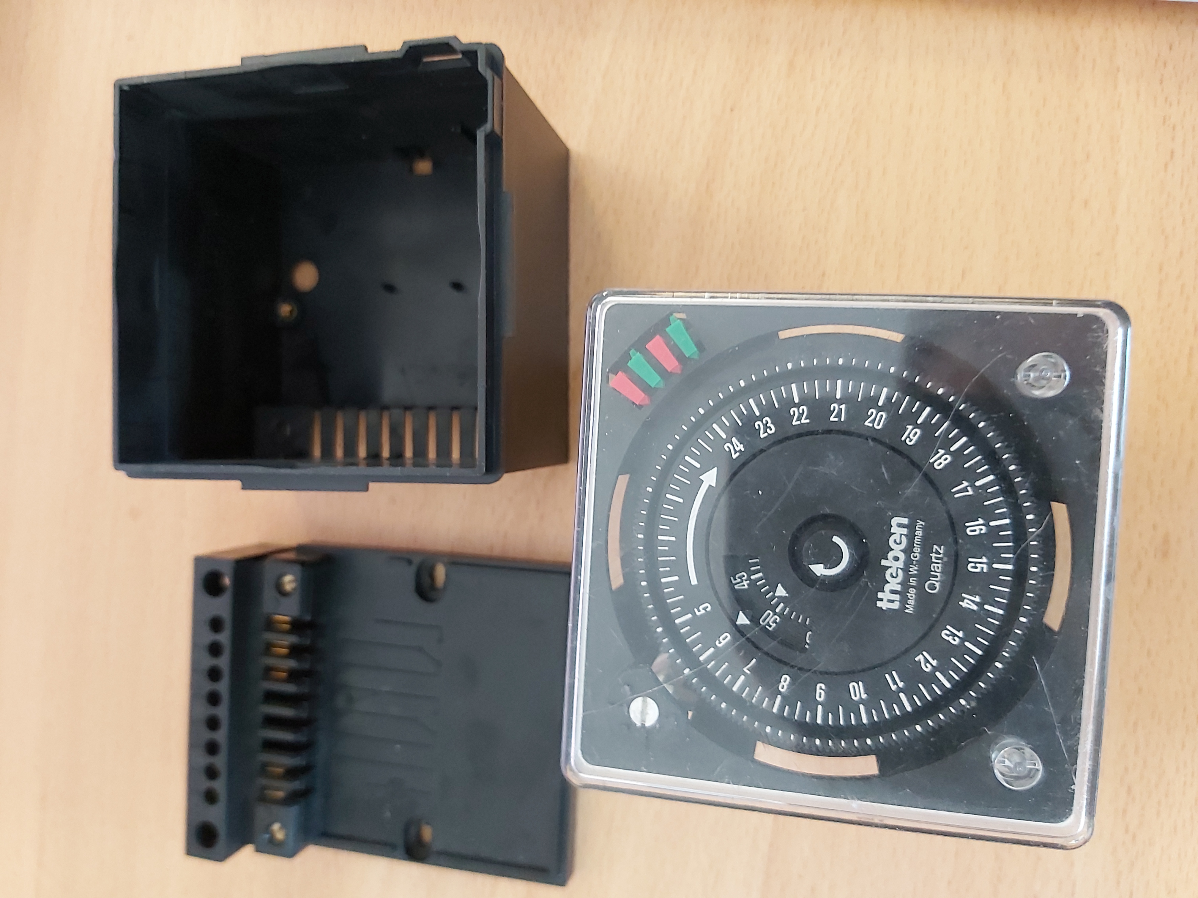
Many mains power timers use mechanism that has mains powered syncronous motor, but this is different. This one has a electronic clock timer in it. There seems to be one clock IC with a crystal (around 4.19 MHz). The clock IC drives the stepper motor mechanism that moves the mechanical clock that controls the mains switch contacts.
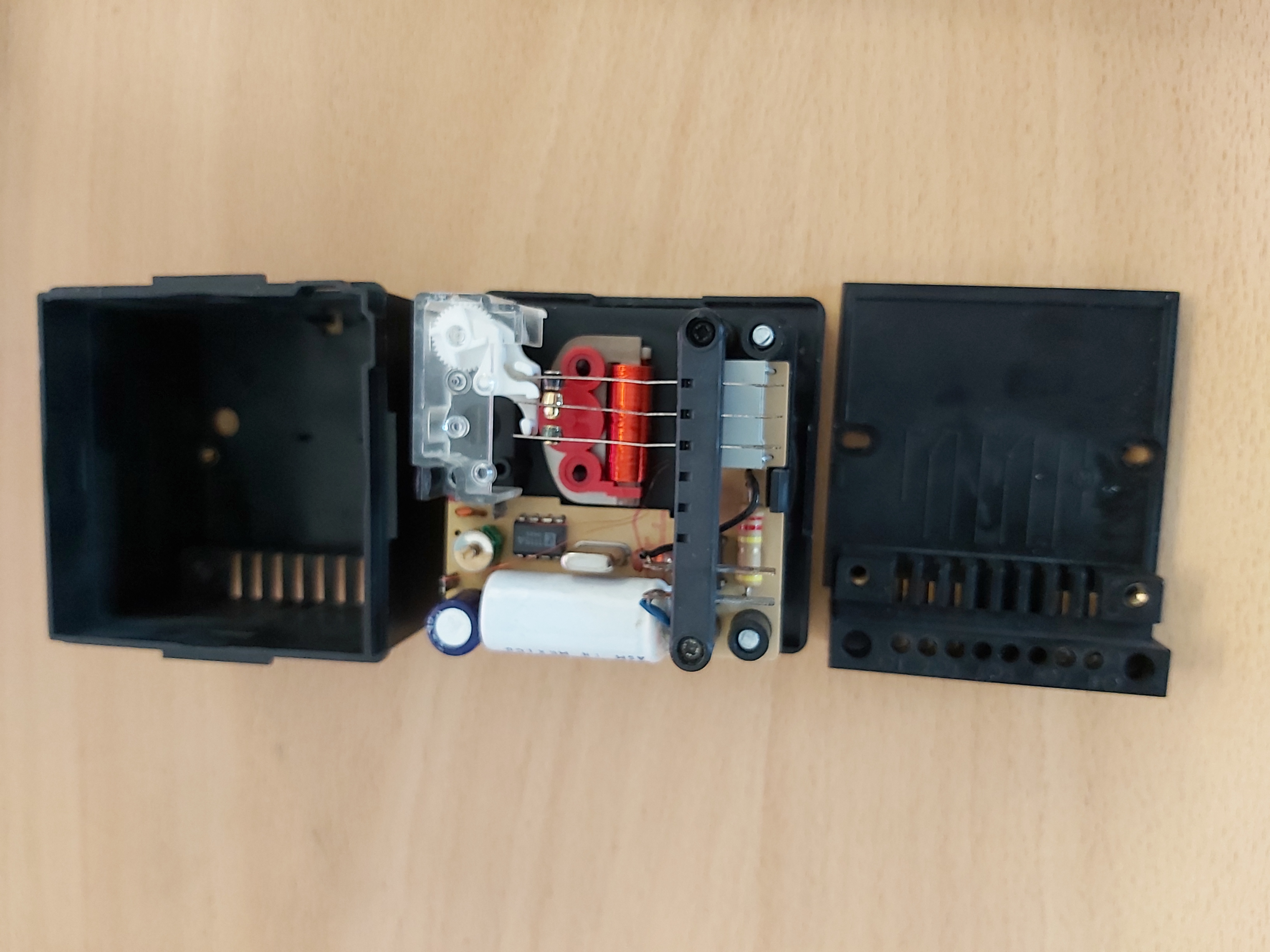
The clock is powered from mains power using transformer-less power supply. That power supply consists of a capacitor, power resistor and bridge rectifier. The output from bridge rectifier goes to a resistor, which charges the rechargeable battery, main capacitor and the clock chip. I could not see any zener diodes in this circuit, and I suspect that the rechargeable battery is used here also as the component that regulates circuit voltage (NiCad battery might act the same as a Zener diode). The battery has leaked which could be a reason why this does not work properly.
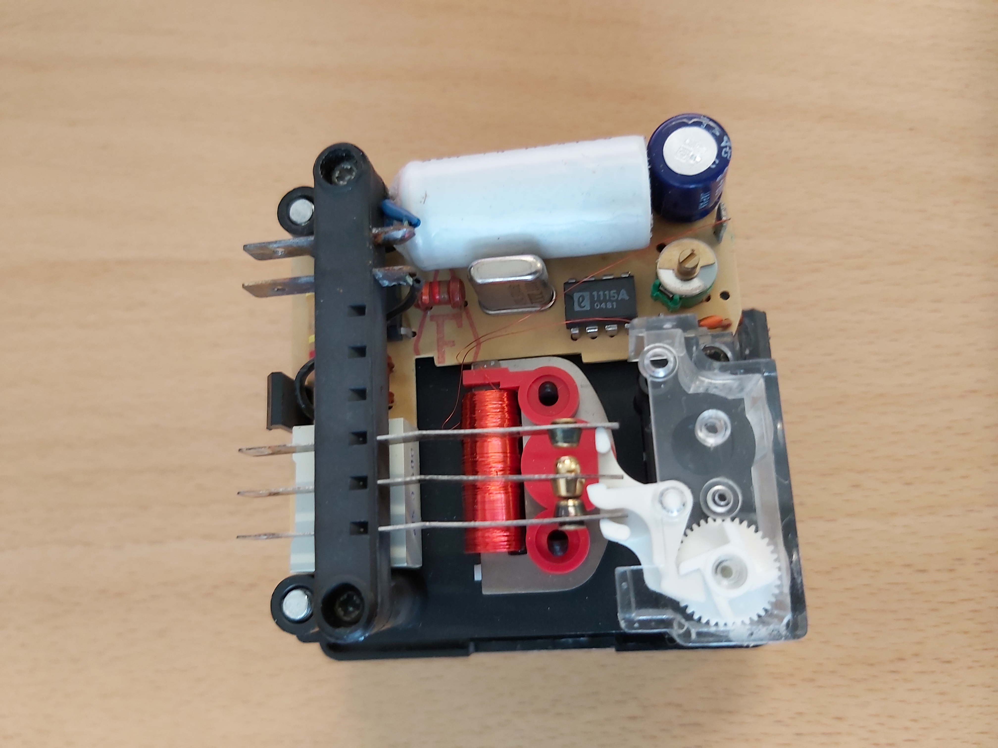
The clock electronics is based on Eurosil 1115A that is an 8-pin clock chip which drives a stepper motor. It is equivalent to Intersil’s ICM1115A that has datasheet at https://www.datasheetcatalog.com/datasheets_pdf/I/C/M/1/ICM1115.shtml
Page 132 of the following document lists several Eurosil TIMEPIECE-WATCH/CLOCK ICs as cross references for Samsung parts: http://bitsavers.informatik.uni-stuttgart.de/components/samsung/1988_Samsung_Semiconductor_Product_Guide.pdf
Sources:
https://www.eevblog.com/forum/repair/recognize-this-ic/
https://www.badcaps.net/forum/showthread.php?t=8772&page=2
4 Comments
drift boss says:
I appreciate you sharing this important information with us
DooFlix says:
A digital timer clock teardown involves disassembling the device to understand its internal components and functionality.
poptropica says:
This is an interesting take on power timers! The use of an electronic clock timer instead of a synchronous motor is quite innovative. Perhaps more examples of such advancements in everyday devices could inspire gamers and tech enthusiasts alike.
slope unblocked says:
Wow, a digital timer innard reveal! Funny, I always wondered what made those things tick. Speaking of ticking, this clock’s guts are way more complex than I imagined. I remember trying to fix an old VCR timer once. Slope Unblocked, it was a disaster! Sparks flew, and I nearly short-circuited the whole house. It was way beyond my level. I think I stick to software from now on.