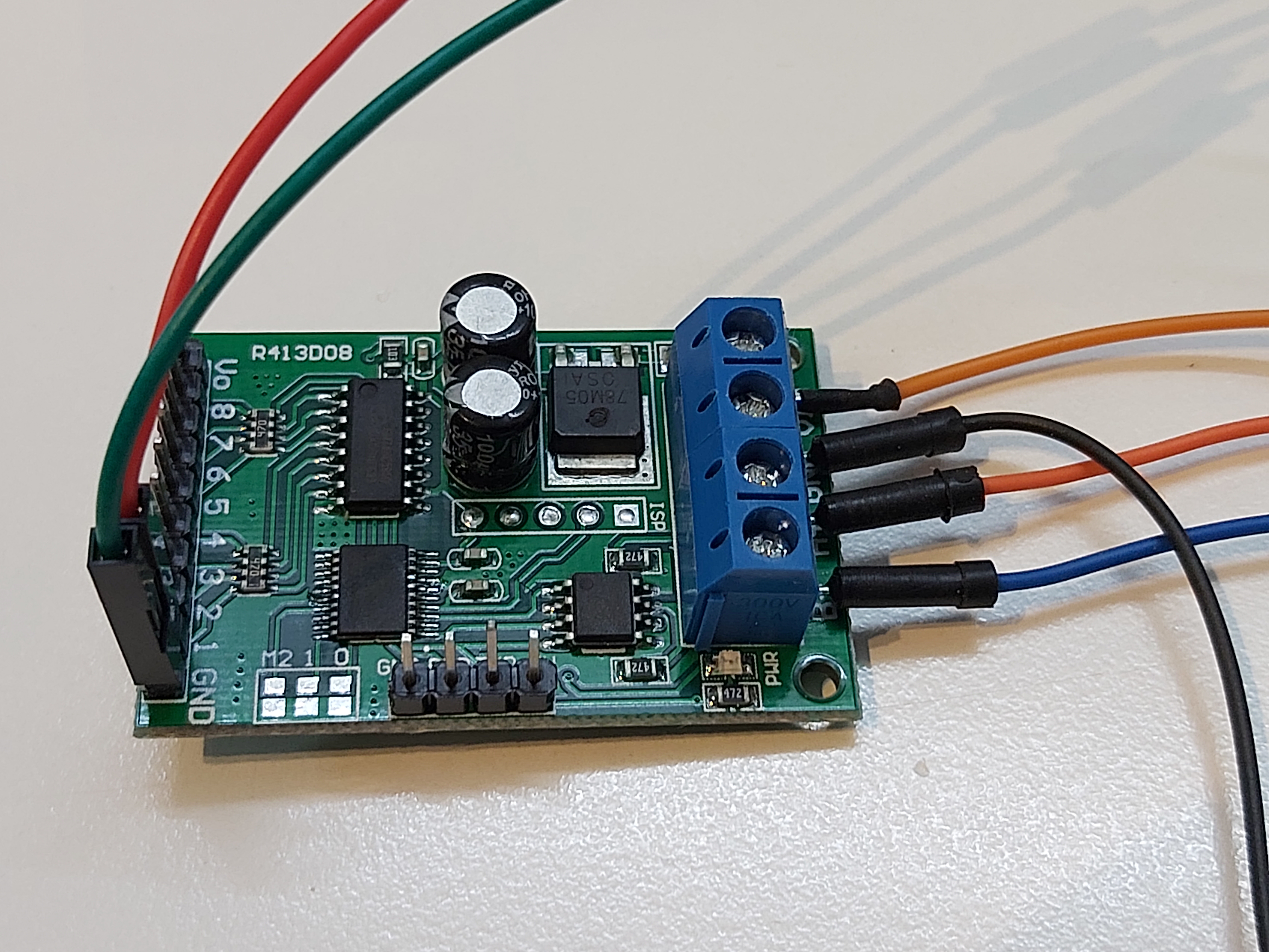
R413D08 is a 8 channel relay control board that is designed to be controlled from your computer through through the RS-485 interface. The idea is that this board takes control commands from computer (MODBUS or AT commands) and gives out signals that can control relays. The output from this card are 5V TTL level signals that are suitable for controlling many different relay boards.
R413D08 DC 5V 12V 24V 8ch RS485 Modbus Rtu Control Module for Relay PLC Switch technical data:
1: Operating Voltage : DC 5V(5V Version) / DC 6-24V(6-24 Version)
2: Operating Current : 10-15MA
3: ”open” ”close” ”Momentary” ”Self-locking” ”Interlock” ”Delay” 6 Commands
4: Two instruction-control mode : AT command and MODBUS command
5: Under the AT command ,the maximum delay is 9999 seconds
Under the MODBUS command ,the maximum delay is 255 seconds
6 AT commands can be made serial HyperTerminal (serial assistant) Enter;
MODBUS commands can be made serial HyperTerminal (serial assistant) OR ”Modbus Poll” Enter;
7 Under the MODBUS command mode, it can support up to 247 devices in parallel
8 With RS485 and RS232 (TTL) dual bus interface
9 Output control pins 8, 5V TTL level, low level (default) / high level output
10 Size: 45 * 30 * 15mm
11 Weight: 10g
Function description:
“Open”: Control port outputs low level (default)
“Off”: Control port outputs high level (default)
Here is an application example from R413D08 DC 5V 12V 24V 8ch RS485 Modbus Rtu Control Module for Relay PLC Switch product page:

Here a cheap USB-RS485 converter convers the data from computer to RS-485 format, and the board receives the data.
Modbus controlling
Modbus or MODBUS is a client/server data communications protocol in the application layer. It was originally published by Modicon (now Schneider Electric) in 1979 for use with its programmable logic controllers (PLCs). Modbus has become a de facto standard communication protocol for communication between industrial electronic devices in a wide range of buses and network.
This board supports MODBUS communications. The default communications parameters are 9600 Band ,8 Data bits,None Parity,1 Stop Bit. The default MODBUS slave address is 01.
Here is table from https://github.com/microrobotics/R413D08/issues/1 page that describes the supported MODBUS read commands:
| Bytes Number | 1 | 2 | 3 | 4 | 5 | 6 | 7 | 8 |
|---|---|---|---|---|---|---|---|---|
| MODBUS Definitions | Slave ID | Function | Address | Data | CRC Check | |||
| Function | Device Address | Function | Starting register address | Register length | CRC Check | |||
| Read Channel 1 State | 0×00-0x2F | 0×03 | 0×0001 | 0×0001 | ||||
| Read Channel 2 State | 0×00-0x2F | 0×03 | 0×0002 | 0×0001 | ||||
| Read 2 consecutive channels status | 0×00-0x2F | 0×03 | 0×0001-0×0003 | 0×0002 | ||||
| Read 3 consecutive channels status | 0×00-0x2F | 0×03 | 0×0001-0×0002 | 0×0003 | ||||
| Read all 8 channels status | 0×00-0x2F | 0×03 | 0×0001 | 0×0008 |
When you read relay state, value 0×0001 means open and 0×0000 means closed.
The MODBUS address can be changed and if it is unknown, it can be read with “Read Slave ID” request: FF 03 00 FF 00 01 A1 E4
Here are the relay control commands:
I found the most useful command to be this direct control commands.
Command 0×06
Address 1-8 relay number
Values:
Open 256 (0×0100)
Close 512 (0×0200)
There are also commands that support more advanced features, for example opening or closing relay after predefined delay time. Under the MODBUS command the timing resolution is one second and the maximum delay is 255 seconds
More command details can be found in manual at https://github.com/microrobotics/R413D08/files/5689915/8.Channel.Multifunction.RS485.Module.command.pdf
AT commands
The Hayes command set (also known as the AT command set) is a specific command language originally developed for controlling modems. The command set consists of a series of short text strings which can be combined to produce commands for operations such as dialing, hanging up, and changing the parameters of the connection. It has been also adapted for other uses as well. In this product the AT command set is used to control the relays.
The module needs to be set to AT command mode to be able to use AT commands. This is done by making M0′s two pads are soldered together or connected with other means.
The communications worked well through RS-485 using TeraTerm terminal program with 9600 8N1 no handshake communications settings and the following terminal settings:
Here is the AT command (ASCII) overview if you want to try to use them:
Read Status:
Channel 1: AT+R1
Channel 2: AT+R2
Channel 3: AT+R 3
Channel 4: AT+R 4
Channel 5: AT+R 5
Channel 6: AT+R 6
Channel 7: AT+R 7
Channel 8: AT+R 8
Open relay:
Channel 1: AT+O1
Channel 2: AT+O2
Channel 3: AT+O3
Channel 4: AT+O4
Channel 5: AT+O5
Channel 6: AT+O6
Channel 7: AT+O7
Channel 8: AT+O8
Close:
Channel 1: AT+C1
Channel 2: AT+C2
etc..
Toggle (Self locking):
Channel 1: AT+T1
Channel 2: AT+T2
etc.
Latch
Inter locking
Channel 1: AT+L1
Channel 2: AT+L2
etc..
Momentary
Non locking )
Channel 1: AT+M1
Channel 2: AT+M2
etc.
Delay
Channel 1: AT+D1=XXXX
Channel 2: AT+D2=XXXX
etc.
XXXX = refers to the 0000 to 9999 figures, Unit is seconds
Under the AT command ,the maximum delay is 9999 second (over 2.7 hours).
Example 1:
Send command
“AT+ 0010 “”, Channel 1 is ” Open “”, after delay of 10 seconds, channel 1 is Close
Send command
” D 2= 0 10 0 “”, Channel 2 is ” Op en “”, after delay of 1 0 0 seconds, channel 2 is Close
Example 2:
Send command
“AT+ L1″, Channel 1 is ” Open “”, other C hannel s is ” Close
Send command
“AT+ L2″, Channel 2 is ” Open “”, other C hannel s is ” Close
More command details can be found in manual at https://github.com/microrobotics/R413D08/files/5689915/8.Channel.Multifunction.RS485.Module.command.pdf
More information
Links to more information:
5V 6-24V RS485 RS232 R413D08 8 Channel (TTL) Modbus RTU Control Module Multi-Function Relay PLC Control Board
https://www.aliexpress.com/i/1005003098396828.html
This RUST project can read and write a R413D08 module from the command line.
https://github.com/acpiccolo/R413D08-Controller/blob/main/README.md
RS485MODBUS V3.O
Software utility for STM8S103, R421A08, R221A04, R413D08 relay board
https://sourceforge.net/projects/rs485modbus/
R413D08
8 Channel Relay Control Module – RS485 & RS232
https://github.com/microrobotics/R413D08
Linux app named RS485modbus
https://www.onworks.net/software/app-rs485modbus
Product R413D08, USB to RS485/RS232 – documentation?
https://github.com/microrobotics/R413D08/issues/1
Product pages:
R413D08 DC 5V 12V 24V 8ch RS485 Modbus Rtu Control Module for Relay PLC Switch
https://www.ebay.com/itm/333654114235
5V 6-24V RS485 RS232 R413D08 8 Channel (TTL) Modbus RTU Control Module Multi-Function Relay PLC Control Board
https://www.aliexpress.com/item/1005003098396828.html
1 Comment
Tomi Engdahl says:
https://www.ls-homeprojects.co.uk/dps3005-psu-module-and-modbus-rtu-python-arduino/