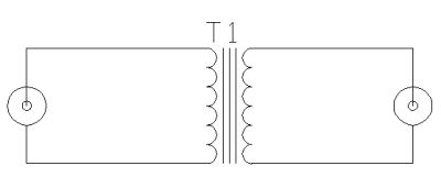
Video isolation transformers are primarily used in CCTV application in fields of security, manufacturing, avionics and display. The video isolation transformer is an extremely broad bandpass 1:1 isolation transformer. Its hum isolation is very good and it can sustain very high noise voltages without degradation. Isolation decreases with increasing noise frequency.
Video signals can transformer isolated in many applications. Most video signal transport paths are AC coupled, so this kind of signal can pass through a suitable transformer. Video isolation transformers are used CCTV applications where they solve ground loop problems or protect system against ground potential differences between different locations.

The design of a high bandwidth transformer which can go to very low and very frequencies is very hard. Video signal can have significant signal components from 50 Hz up to 6 MHz. Unfortunately in practical transformers you have to always make some compromises on low and high frequency responses (highest components of composite video can be attenuated even few dB). Signal amplitude at low frequencies is limited by core saturation and coil inductance. High frequency response is limited by leakage inductance and winding capacitance. Many video isolation transformers are only designed for CCTV other not so demanding applications application, where more signal distortion is accepted than in broadcast industry.
Lundahl LL1575 is a high bandwidth video isolation transformer designed for CCTV (closed circuit television) applications. I have used that transformer successfull to build video video isolators. That transformer has 20 Hz – 11 MHz +0 /- 3 dB frequency response (possible with special bifilar winding technique and special core construction). That transformer gives 2 kV rms isolation between primary and secondary windings.
The LL1575 datasheet recommends that if DC current is present, the transformer must be decoupled (with large capacitor). Because in many video circuits there can some DC present especially in video outputs, I thought that it would be a good idea to include suitable DC blocking capacitor to the circuit input side (on the left, connected to video signal source output). A suitable capacitor value should be 1000 uF or higher (practically demands using electrolytic capacitor) and have good high frequency characteristics (electrolytic capacitors are not good at this, ceramic etc.. would be much better here). The capacitor I used was built from 4700 uF electrolytic capacitor (gives capacitance) wired in parallel with 100 nF ceramic capacitor (handles the high frequencies where electrolytic capacitor is not good at). 25V or higher voltage rating is suitable for the application (you normally see 1Vpp video signal plus maybe few volts DC).

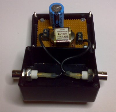
The circuit is best constructed to a small plastic box with suitable connectors. For professional applications I recommend to use BNC connectors. If all your equipment use RCA for video signal, then use those connectors if they are easier for you. Plastic box is easiest for the construction because in this way it is easy to guarantee good electrical isolation between input and output side connectors (in metal box needed isolation could be hard to do reliably).
Here ia picture of the video isolator I have built:

28 Comments
Business Security Cameras says:
I found your blog via Google while searching for business security cameras and your post regarding Build video isolator « Tomi Engdahl’s ePanorama blog captured my attention. All I can say is WOW! Extremely nice layouts, awesome graphics and great articles. matter how many times I come here, I am still impressed by the very professional appearance. Congratulations on a job well done.
Allene Cassar says:
Awesome Blog, Bro! Admitedly I’m a home security fanatic and am constantly on the watch for new and interesting sites and posts about interesting home security related stuff… which is what led me here. Any who how i just wanted to check in as I certainly plan on visiting again! Cheers
Tyree says:
Wow. http://www.epanorama.net is amazing.
tomi says:
Yes. Good publicity is always good news for this blog and ePanorama.net
tommy says:
Just wanted to say I enjoyed the post. You have really put a lot of time into your article and it is just great!
tomi says:
Does anyone else has problem on URL feed?
The problem could be in the browser side if this comment at http://en.forums.wordpress.com/topic/rss-issue-when-viewing-in-google-chrome is true:
Chrome has huge problems viewing RSS feeds, and yes, WP.com is aware. I think they’re waiting for a Chrome upgrade to fix it.
Surprising that Google of all companies would have such a hard time making a browser that functions with a tool that essentially speeds up reading / searching…
Jon Brink says:
I think audiophiles need to worry less about the perfection of sound and instead try to immerse himself (or herself) in the music.
Andrew Pelt says:
Wow i did not know this
Grace Cavendish says:
I genuinely appreciate your writing style. That is a wonderful post! Thanks!
Kredyty says:
Very informative post. Thanks for taking the time to share your view with us.
home video surveillance internet says:
Hi guy, It sounds really good!
PTZ IP camera says:
Hi there, anyway, thanks for the info!
Jon Brink says:
Couldn’t agree with you more.
Ferdinand Aranjo says:
This kind of an amazing article! I really enjoy Studying it, very Fine insights, the article is very ell-Stated. A thumbs up!
Secured by design says:
Interesting instructions; I’m going to try this out when I have the time.
Arnold says:
Wonderful article. I was looking at this website and that i’m impressed! Extremely helpful information especially the previous aspect I attend to this kind of information lots. I was looking for this certain data for some time. Appreciate it and enjoy.
Darnell says:
Hey are utilizing WordPress for the web site system? Iam new to blog entire world however. Iam hoping to get started out and set up my very own. I also discovered Drupal is ok. Sees my own option…. Helpful post, thank you.
tomi says:
I am utilizing WordPress for this blog.
Most other parts of the site run on a custom built web publishing system.
Audio and video signal susceptibility classes « Tomi Engdahl’s ePanorama blog says:
[...] solution is to add audio isolation transformer. For analogue video signals the normal solutions are video isolator and humbugging transformer. Those additional tools can usually increase in the best case the [...]
Video over UTP « Tomi Engdahl’s ePanorama blog says:
[...] is inside those baluns? Let’s start with the most obvious solution: isolation transformer. Build video isolator shows a construction of video isolator [...]
Gregory says:
You really know what you are talking about. I will definitely show this to my friend.
stentor says:
I think for less demanding applications cheap ($5-10) off-the-shelf baluns or even DIY made from the junk heap will do. Those Lundahl transformers aint cheap.
Tomi Engdahl says:
You are right. For less demanding applications there are cheaper options.
Tomi Engdahl says:
https://www.canford.co.uk/Products/22793/90-542_CANFORD-VIDEO-ISOLATOR-Analogue-video-isolation-transformer-single-channel
https://www.amazon.com/slp/ground-loop-isolator-for-audio-video/yjyw4vfsybns4h2
Tomi Engdahl says:
Homemade Injection Transformer for PSU Loop Analysis
https://adilmalikn.wordpress.com/2019/07/07/homemade-inject-transformer-for-psu-loop-analysis/
Recently, I have been designing some SMPS and required some hardware to measure the actual loop response of the complete converters. People familiar with this area will probably know this can be done breaking the feedback loop of the converter and injecting a small AC signal and measuring the loop response at the output of the converter. However, such a measurement requires a mechanism to inject this signal differential across a small resistor inline with the normal feedback network. Unfortunately, as most signal generators are ground referenced we need special hardware to convert this output to a floating output.
Commercial PSU analysers come with expensive injection transformers that allow us to do that. These transformers are designed to have a very flat response in the region of conventional loop bandwidths of SMPS converters, these range from a few Hz to upto a few MHz.
For example this transformer for the Bode-100 costs $500!
The reason these transformers are so expensive is the use of exotic cores that result in high inductance with minimum turns. This way the low frequency behaviour of the transformer is improved without degrading the high frequency. Simply speaking, we need to add more turns to the transformer to improve low frequency behaviour, but the increased parasitic capacitance then degrades the high frequency behaviour.
I experimented with a few DIY transformers by purchasing some cheap £10 cores from RS. I wound around 5m of differential cabling scavenged from an old Ethernet cable.
The results are surprisingly flat, and both transformers work well from about 10 Hz upto 5 MHz, and should be usable upto 10 MHz. Not bad for £10!
Make your own insertion transformer for measuring loop gain-phase of power converters
http://www.simprojects.nl/images/DIY_signal_injection_transformer.pdf
Tomi Engdahl says:
Inductance values for various designs
http://www.richieburnett.co.uk/temp/gdt/gdt1.html
The pictures below show various different pulse transformers that were tested. The core type and winding method are listed along with the measured inductances.
Tomi Engdahl says:
EEVblog #1104 – Omicron Labs Bode 100 Teardown
https://www.youtube.com/watch?v=IpI-cGU6-FY&t=7s
Viewer comments:
In RF land we call that a transmission line transformer. At low frequencies, the ferrite coupling does the heavy lifting, and at high frequencies, the transmission line coupling does the heavy lifting. Simple in principle, but getting the crossover really flat in amplitude and phase takes a good bit of experimentation.
this starts to make sense now
Lots of people claiming they could make a wideband injection transformer for a few bucks. Time for a competition perhaps Dave?
It is one thing to make 1 of those.
Producing lots of them is a completley different thing!
$15 for the parts, $485 for the virgins..
I actually did a “mini-internship” at Omicron in Austria a few years back. No nude virgins assembling the devices though :/
Clothed virgins, males.
Its a specific piece of test equipment. If you need one you don’t particularly worry about the cost; it’s a drop in the bucket compared to all your other test gear
Btw you can make directional couplers, hybrids ,circulators etc with good opamps at arbitrary impedances. At 10 Mhz this is no big deal!
The term you were looking for on the transformer was “bifilar windings” it is a common trick for making a broad band transformer.
As an injection transformer, it is usually better to have a 10:1 step down so that the 50 Ohm output impedance of your generator looks like 0.5 Ohms on the system under test.
I was slightly surprised by the small cross section of the core. Generally, the more massive the core the more energy it can store. On the high current side of the transformer, you can have significant DC current leading to significant stored energy in the transformer’s core.
Top tip for anyone wanting to make a transformer with better performance than this: Use binocular ferrites. Hard to get, but if you are serious about being a manufacturer of quality test gear, it is viable when you are charging hundreds of bucks for a wideband flat transformer. If you are being really snazzy, use a pair of binocular ferrites.
The transformer is bifilar wound. The capacitive coupling aids the high end of the BW.
The twisted pair is a type of bifilar winding. It insures the two transformer coils occupy on average exactly the same magnetic space as each other allowing for an almost perfect one-to-one ratio. A typical accuracy of such a winding can be better than 1 PPM.
tomi says:
I will check how this blog works on iPad when I get my hands on one.