I saw an interesting kit at banggood.com and decided to try it: DIY Meter Tester Kit For Capacitance ESR Inductance Resistor NPN PNP Mosfet M168 . The reasons for interests are good specifications, based on open source hardware design and price is reasonable ($12.22 / 9.37 Euro).
DIY Meter Tester Kit For Capacitance ESR Inductance Resistor NPN PNP Mosfet M168 is an electronics component measurement device. It can detect component types and measure them. The meter has automatic detection PNP and NPN type bipolar transistors , N, P -channel MOSFET, JFET FET , diodes , two diodes, thyristors , resistors , capacitors , inductors. You can connect the measurement wires to components as you want, the automatic detection pin definitions will tell which wire is which pin.
The meter features single key measurement operation: Just press key and meter does measurement automatically (determine component type and measure it’s values). Each test time is about two seconds , only large capacitance and inductance measurements will take a long time. The device has auto power off with delay.
The device can be powered with 6FF22 9V Battery, or DC 5.5V ~ 12V via DC socket. The kit has 25 mA operating current and 20 nA current in shutdown, so suitable for battery operation (without separate power switch).
Measurement Ranges:
Resistor: 0.5Ω ~ 50MΩ (resolution is 0.1Ohm)
Capacitor: 30pF ~ 100mF (resolution up to 1PF)
Inductance: 0.01MH ~ 10H
Potentiometer: Support two measuring resistors connect at the same time -> can measure potentiometer
ESR measurement: Can detect more than 2UF capacitor equivalent series resistance (ESR), with a resolution of 0.01Ohm.
Bipolar transistor: amplification factor (B) and conduction voltage emitter junction (Uf).
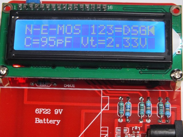
MOSFET: threshold voltage and gate capacitance measurement
Thyristor and TRIAC: meter shows only the component pin-out
Diode: diode direction, voltage drop and capacitance
Zener-diode: If reverse break down Voltage is below 4.5V, these are shown as two diodes with different voltage drops
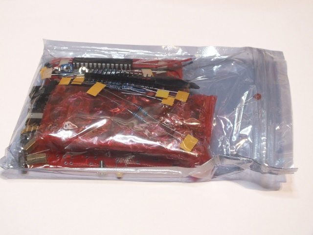
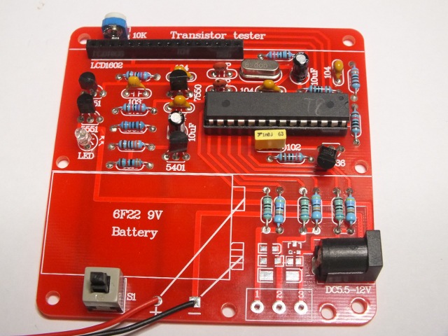
This device is sold as DIY kit that you must solder yourself. The kit comes in a small plastic bag that included all the components and circuit board.
The parts and board are excellent quality, no missing or wrong parts.
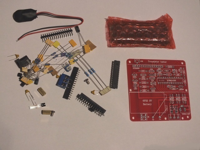
Beginners beware – there are no instructions or documentation with this “kit”, it is a PC board and a bag of parts. That’s it. But, that’s okay because when you install the parts per the component outline/value printed on the top of the PC board.
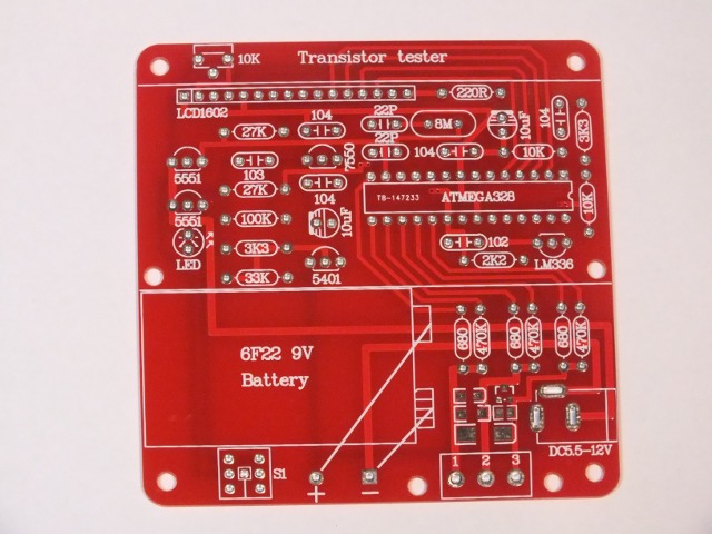
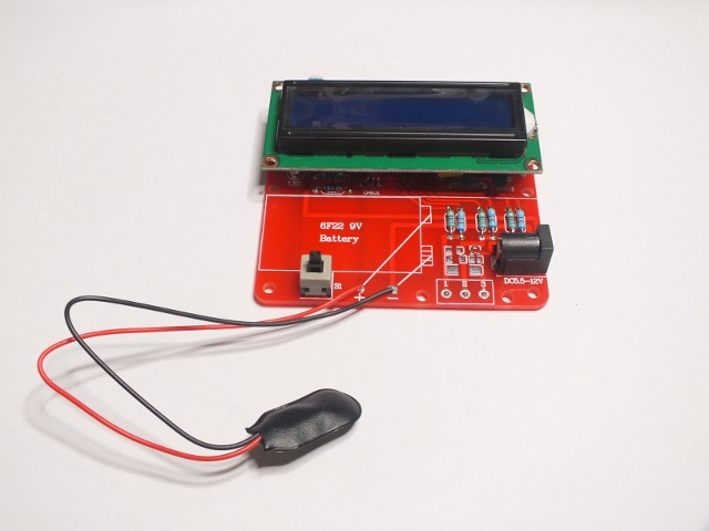
When you put all components in right places add the solder – you’ll end up with a working instrument.
Only problem I had building: There was no clear indication the way the button should installed to circuit board. I first accidentally installed in wring way, and the circuit worked a little bit strangely (but almost worked). When I turned around it (needed de-soldering and re-soldering), everything stated works well as designed.
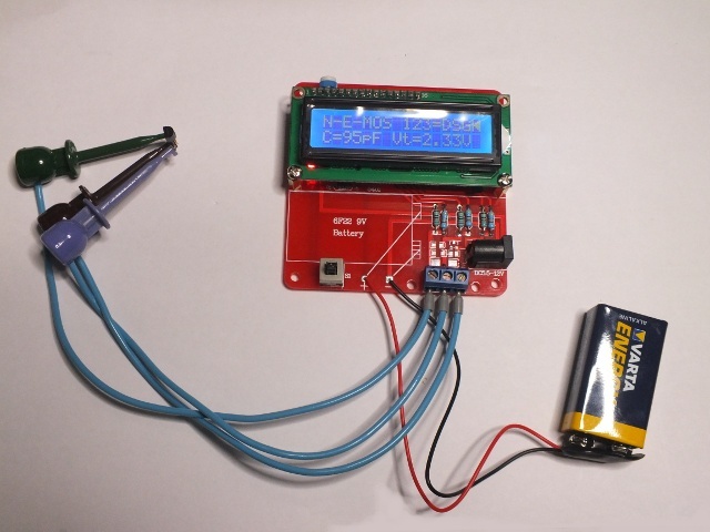
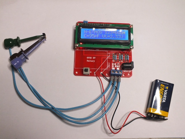
Here is my circuit (with my own measurement leads added to kit) measuring BS170 FET:
This kit is an accurate implementation of the open source project described in all detail at http://www.mikrocontroller.net/attachment/143813/TTester_096k.pdf and a newer version of it at http://www.mikrocontroller.net/attachment/164956/ttester_eng104k.pdf. Since the PC board in this kit implements the open source project schematic with 100% accuracy, the board also uses the open source AVR code. This allows you to extend the design, change its behavior or just use it as is, the choice is yours.
This version uses the ATMEGA328P-PU (same 28 pin DIP package that the Arduino UNO uses). The unit does provide the same 2.1/5.5 MM power jack as used on Arduino’s if you want to power it with a 9vdc wallwart.
There are few negative things on the design:
1) The press to test switch is lacking a large surface to press.You might want to add a small cap to it or replace the original button with your own more user friendly button.
2) The choice of LCD (white on blue) requires the use of the LED backlight always. This backlight uses considerable battery power. The display is standard 1602 device so it should be possible to change if you want to experiment (cost few dollars).
3) The placement of the 3 point terminal strip in front of the SMD pad areas is not good: Having the terminal in front of the pads makes it almost impossible to easily test surface mount parts by pressing them on the board. If you always use measurement wires this is not a problem.
4) The ATMEGA328P processor: while it was in a good static shielding bag, there was no lead protection, it was just tossed in with the other parts which resulting in some bent pins.
5) ESR measurement and the results of inductance measurement are not very accurate.
There are some negative things, but overall I was very satisfied with DIY Meter Tester Kit For Capacitance ESR Inductance Resistor NPN PNP Mosfet M168 kit. This useful instrument will sit on my electronics lab for a long time.
36 Comments
Niclas Ek says:
Did you make any reference measurements on ESR and inductance? It would be interesting to know the accuracy of this meter.
Tomi Engdahl says:
The claim that “ESR measurement and the results of inductance measurement are not very accurate” is based on fact that the measurement results vary quite much (up to several percent at some cases) between different measurements made by just pressing the button (not changed anything). This variation applied to certain inductance and ESR measurements. On some other components with different values those seemed to have better accuracy (less changes in values).
Also the original design documentation said “ESR measurement and the results of inductance measurement are not very accurate”
I might do some more measurements against some other instruments…
Tomi Engdahl says:
I did some testing comparing my RCL meter (Lutron LCR-9063) to M168 kit. The results with several half watt resistor size coils were quite accurate (few percent or less error typically). When I measured transformer coils or large chokes with ferrite or powder core, the results varied often 10-30 percent (few cases even more). Those same coils can give slightly different results in every measurement with m168 and stable reading on other meter.
Tomi Engdahl says:
Inductance measurement method use in M168 according to
http://www.mikrocontroller.net/attachment/164956/ttester_eng104k.pdf pages 51-52
The measurement of inductance values will be done as separate part with all found resistors with
less than 2100 . The methode of measurement is based on the growing of current by formula
after switching on the current. The time constant is proportional
to the inductance L, but reverse proportional to the resistor R. The current can only measured
indirectly with the potential drop of a resistor.
The measurements are always done in both current directions. The
program will select the higher result of measurement in the same current direction, but the lower
result of the diFFerent current direction as the displayed result.
The Inductors above 1H are relays or primary sides of power transformers, for which measurements
are difficult because the iron core has residual remanence.
Tomi Engdahl says:
ESR measurement techniques used according to
http://www.mikrocontroller.net/attachment/164956/ttester_eng104k.pdf pages 40-43:
If the measured capacitor has a capacity of more than about 2F, the tester will try to measure the
series resistance too.
Strictly speaking the ESR of a capacitor depends on the operating frequency and temperature.
Usually the value measured with sine wave-form signal of 100 kHz is denoted in the data sheets. This
measurement can not be done with the ATmega without external equipment.
the voltage of both connections will be measured during
oading in one direction with the ADC internal reference voltage (1.1 V). After the measurement
the load current will be switched off and the voltage of the capacitor is measured again without the
current.
The difference of capacitor voltages with and without current is proportional to the internal
resistance of the capacitor. The expected voltage of this difference is so low, that one measurement
can not result to a feasible result.
Anyway the results seems to be practical
Tomi Engdahl says:
I did some testing on the ESR measurements against my homebuilt ESR meter circuit I built some years ago. It seems that the ESR measurement on M168 give useable results for identifying if electrolytic capacitor is good or that. On some capacitors the results were pretty similar on both instruments, and on some other there was some variation. But in each tested case I got results that were useful for determining if capacitor was OK or not. The ESR measurements are never so that you are interested in accurate milli-ohms reading, you just need reading from which you can determine if the tested capacitor is OK (ESR resistance in good and expected range) or it is bad (ESR considerably higher than you would expect from good one).
Here is link to my earlier posting on ESR meters:
http://www.epanorama.net/newepa/2013/01/17/esr-meters/
Tomi Engdahl says:
This looks like a ready made boxed version of M168 kit:
MK-168 Transistor Tester Diode Triode Capacitance ESR resistance Meter
http://www.banggood.com/Transistor-Tester-Diode-Triode-Capacitance-ESR-Resistance-Meter-p-919181.html?p=27131452996820140438
Sylvain Lazare says:
Hi Tomi Thanks fort your nice presentation. I a wondering if eventually the program is lost or damaged somehow, how tout reload it into the AT328. Is it available somewhere? Sylvain
Tomi Engdahl says:
The project has web page at http://www.mikrocontroller.net/articles/AVR_Transistortester
It points to software and hardware archive at
http://www.mikrocontroller.net/svnbrowser/transistortester/
There is firmware download link (seems to be source code archive) at
http://www.mikrocontroller.net/svnbrowser/transistortester/Software/Markus/?view=tar
Tomi Engdahl says:
I got an idea: While M168 was not designed for testing optocouplers, I got some results with PC817 optocoupler when did following:
Wired – side of LED and output together and to one M168 probe.
Connected other probes to free pins (LED + and output +).
With this method I got it detected as NPN transistor with B=1 (-> CTR=1 in optocoupler).
The base voltage measurement gave LED voltage drop (around 1V).
I have not made any wider testing on selection of different optoisolators…
Tomi Engdahl says:
Same circuit as in previous comments:
Another test with 4N35 optocoupler (nominal minimal CTR=100% in datasheet):
NPN B=1 Uf=1.08V
Test with H11AA2 (AC input optocouplet CTR=10%):
Shows as two diodes
Test on CNY17F-1 (CTR=40%):
Identified as diode
Test 4N27 (CTR > 10%):
Identified as diode
Verdict: Optocoupler could testing could work in some cases. The CTR of the optocoupler needs to be around 100% or more for test to detect it as transistor (less than that M168 will tell it is just diode/led).
Tomi Engdahl says:
This looks like to be a readily built version of M168 circuit for just few dollars more than the kit I tested (hopefully performs as well):
SMD/DIP Transistor Tester Diode Triode Capacitance ESR Meter MOS PNP NPN
http://www.banggood.com/SMDDIP-Transistor-Tester-Diode-Triode-Capacitance-ESR-Meter-MOS-PNP-p-928099.html?p=27131452996820140438
Tomi Engdahl says:
Some more notes on inductance measurements:
I earlier wrote: “I did some testing comparing my RCL meter (Lutron LCR-9063) to M168 kit. The results with several half watt resistor size coils were quite accurate (few percent or less error typically). When I measured transformer coils or large chokes with ferrite or powder core, the results varied often 10-30 percent (few cases even more). Those same coils can give slightly different results in every measurement with m168 and stable reading on other meter”
On the coils with cores I have found out that in most cases there is quite a bit of variation on inductance measurement result on first few measurements. After that the measurement resulst typically start to stabilize to give very close results on inductance, and those results are usually much closer to the right value. So if you measure coils with some magnetic core, try doing few measurements (press the button and wait few seconds several time) before really start reading the inductance values. You get in this way more accurate results. Maybe this has to do with something to do with the magnetism that could stored on the coil core or something…
Tomi Engdahl says:
EDN magazine seems to have covered this:
Clever engineering creates rock-bottom component tester
http://www.edn.com/electronics-blogs/benchtalk/4433481/Clever-engineering-creates-rock-bottom-component-tester
While this sub-$20 board may not gain pride of place in your T&M rack, it’s a fine tool for hobbyist and pro alike, and demonstrates the power of clever design.
Recently, while thumbing through eBay, I stumbled upon what appeared to be a magical everything component tester, for under $20.
The board is billed as being able to test almost anything you might care to throw at it; and it does. Resistors, capacitors, and of course inductors. The ESR of inductors and some capacitors is also displayed, though, in the only failing I’ve found so far, capacitor ESR seems a bit flaky.
I plugged in a very rare type of FET: a depletion mode MOSFET – one that is on at zero gate voltage. Colour me more impressed. The part was recognized too.
business end of the circuit comprises one AVR microcontroller and six resistors. I’ll say that again: one micro, and a few resistors. Markus must have had a ball coding this thing up!
Morlier says:
Can you explain me the object of the LED who is sold on the print board, on my Kit 168, this LED is always off!
I had sold the push-button in the wrong direction too!
excuse me for my english language…
BY
Tomi Engdahl says:
Sounds like you had soldered the LED on the wrong way as well…
Reg says:
I built this today and it does not work no display switch in correctly no Led lit (right way round).
No idea what pot is for (zero set I am guessing).
Tomi Engdahl says:
That potentiometer in the circuit is for controlling the display contrast. It can ontrol practically from no display to completely black display. You need to tune it to get the best image on your display (if completely off what it should be could cause no display).
Johnny says:
I put this bad boy together and was very impressed. have not tried to mount it in the plastic case it came with and I wish the results stayed up longer before it goes to TIME OUT.
Mike says:
Thanks for your article.. it saved me some time identifying all the resistors!
I put this together last night but when I connect the battery the screen backlight comes on but nothing else happens. I THINK it is loading up ok because the LED light stays on for 5 seconds and then goes off and lets me reset it. Where as I can’t reset it within the 5 seconds. So could it just be the screen at fault??
I will check all solder joints later but I am pretty sure they are fine. I am 100% sure I built it right as I spent a good 2 hours on it.
Any suggestions would be appreciated!
Cheers
Tomi Engdahl says:
Check that you have put the start/reset button to the circuit board the right way. You can put it there two ways, but only one of them is right.
When I build my kit I mad this mistake, and got some strange operation – I don’t remember was it exactly same what you got.
I found out the mistake with multimeter….
So start by checking that button.
Mike says:
nevermind. it was the brightness setting. doh!
Cheers
Raveesh H P says:
Dear Sir
I am an average electronic hobbyist and i have purchased M168 tester online which was in DIY kit form one month ago. I have assembled the same with all the required care as I am having sufficient knowledge of soldering. I have tested individual components like resisters, transistors and capacitors using DMM before soldering (it is my usual practice)and all are found to be OK. But to my bad luck the tester is not showing any reading. As soon as I press the switch the display lights and no readings. I have tried with resistance, inductor but it is not showing any reading on the display. Display stays on for some time and gets off. I have checked the position of the switch S1 but it is in order. My enquiry with the online site is in vein. I thought the MCU ATMEGA328 might be unprogrammed and ordered for fresh programmed Atmega328 from Banggood.com. Today i have received the same and on testing with the fresh MCU also the display stays blank.
As such I request you to enlighten me what could be wrong in the tester.
Hope to hear soon positively
Raveesh H P
Tomi Engdahl says:
Have you checked the potentiometer setting on the circuit?
The potentiometer next to the LCD controls the display contrast, it controls the display from “white” to “black”, and only somewhere around in the middle you get readable results. Check this first.
Raveesh H P says:
Yes the problem was with the timpot. After adjustment now the tester is showing the reading. kindly accept my sincere thanks.
One more problem is, it is not showing the inductance reading. if I connect an inductor it simply displays the resistance value of the inductance. what could be wrong.
Thanks a lot once again.
Raveesh
Raveesh H P says:
Dear Sir,
I am an average electronic hobbyist from India & have purchased a tester exactly looking like the one you are discussing above, through online store from china. The tester was in DIY kit format and I have assembled the same with due caution. But the tester is not functioning. The display stays on for some time and gets off but does not show any reading of the component connected acros the test terminal. I have tried with resistors, capacitors and transistors display stays lit but blank. I have checked each component with DMM before soldering (it is my usual practice). I have checked position of test switch S1 and is in order. I am using 7.5 volts DC adopter supply for this tester.
My enquiry with the online store is in vein. I thought the Atmega328 might be blank and programmed and ordered fresh programmed atemega328 with Banggood.com which arrived today. But with this MCU also the display is not showing any reading.
As such I request you to guide me what could be wrong with the tester.
Hope to hear from you positively at your earliest.
With regards
Raveesh H P
Raymond says:
Tomi, I noticed you added probes..big question, does that mean you can use this device to measure caps in circuit? Have you tried it?
What I am really looking for is the ESR portion of the application to test if caps are good or not, but in circuit. Many thanks!
Tomi Engdahl says:
I have not tested much capacitor measurements in-circuit.
Tomi Engdahl says:
There seems to be now available a newer edition of the same idea:
DIY M12864 Graphics Version Transistor Tester Kit LCR ESR PWM
http://www.banggood.com/DIY-M12864-Graphics-Version-Transistor-Tester-Kit-LCR-ESR-PWM-p-986954.html?p=27131452996820140438
Additional Feature:
1. The square wave signal generator, optional built-in within the range of 1HZ-2MHZ stall square wave signal;
2.PWM pulse signal generator for 1-99% of the pulse width modulated signal;
3. The frequency meter function, can test 1HZ-25KHZ or higher frequency signal (in this case a slight decrease in accuracy)
Also in-circuit capacitance ESR measurements.
Manual can be found at
https://www.copy.com/s/t%3AwBdnTSsdB3DBEmT6%3Bp%3A%252F12864tester.pdf%3Boid%3A34
Mark skrivseth says:
I have this meter. I love it for the price.
Mark skrivseth says:
I have this meter. Love it for the price.
denneval says:
Bonjour
Je possède cette version 1,12K . Cependant une question et qui se trouve sur la carte de l’afficheur “1602A’
Je souhaite connaître la référence de U3 qui se trouve sur l’afficheur ainsi que les composants autour de ce CI. Comme de connaître sa fonction ainsi que J1, J2, J3….
Cordialement
Tomi Engdahl says:
Want to Build an Arduino-Based Component Tester?
https://www.eeweb.com/profile/max-maxfield/articles/want-to-build-an-arduino-based-component-tester
These little beauties are amazing value for $15 to $20, and I can no longer imagine not having one on my desk (I just now discovered you can buy this M328 kit version on eBay for only $3.65, which I find to be mind-blowing).
My understanding is that the original tester was created by Markus Frejek, and that this work — which I believe is open source — was subsequently refined by Karl-Heinz Kübbeler. In fact, Karl — who is my new hero — has published this 132-page document describing his work in detail.
On Page 6 of Karl’s opus we read: “Operates with ATmega8, ATmega168 or ATmega328 microcontrollers. Additionally, ATmega644, ATmega1284, ATmega1280 or ATmega2560 microcontrollers can be used.” This is cool beans indeed! The Arduino Uno is based on the ATmega328P, so we’re all set on the microcontroller front.
http://www.avrtester.tode.cz/upload/ttester_en.pdf
On the one hand, you could say “What’s the point?” This is a fair question. Why work yourself into the ground to do something that’s already been done and that you can buy in kit form for only $3.65? My answer would be that building one’s own Arduino shield — along with the associated sketch (program) — would have tremendous educational value.
Tomi Engdahl says:
EEVblog #1020 – Is A $7 LCR / Component Tester Any Good?
https://www.youtube.com/watch?v=7Br3L1B80ow
Is a $7 LCR Meter / Component Tester from Ebay any good?
Dave tests the M328 (LCR-T4) model component tester.
Tomi Engdahl says:
Review: Transistor Tester
https://hackaday.com/2015/04/24/review-transistor-tester/
Tomi Engdahl says:
https://www.uraltone.com/komponenttitesterimoduli.html