CAD tools for programmers

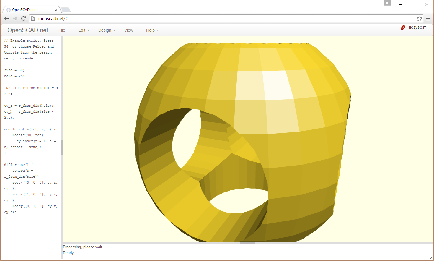
OpenSCAD is a free software for creating solid 3D CAD objects. It is open source software that is available for Linux/UNIX, MS Windows and Mac OS X – and also a version that runs online in browser. After quick testing it looks like OpenSCAD is a really wonderful tool for 3D modeling. While it doesn’t have the traditional graphical interface of AutoCAD – it’s basically a programming language for 3D models – OpenSCAD is able to create very complex parts with only a few lines of code. OpenSCAD allows for two types of modeling – constructive solid geometry, or taking 3D primitives and stretching, scaling, and intersecting them to create a 3D shape, or extrusion from a 2D outline. It should be sitable for making desings for 3D printing as quite a few RepRap parts were designed in OpenSCAD and Makerbot 3D printer maker has OpenSCAD tutorials for this in mind.

If you want to start experimenting with OpenSCAD parts in your browser. There are two alternatives for this. OpenSCAD.net offers one online version of OpenSCAD that runs nicely at least on Chrome browser (failed to work properly in Firefox for me). It is a nice playground to test OpenSCAD.

openscadnet

OpenJsCad is a 2D and 3D modeling tool similar to OpenSCAD, but web based and using Javascript language.
3D solids can be exported as STL files, 2D areas can be exported in a DXF file. OpenJsCAD is written entirely in Javascript and able to be embedded in a web page. To build your own models, create a .jscad file with your javascript code and parse the file using the OpenJsCad parser.

openjscad

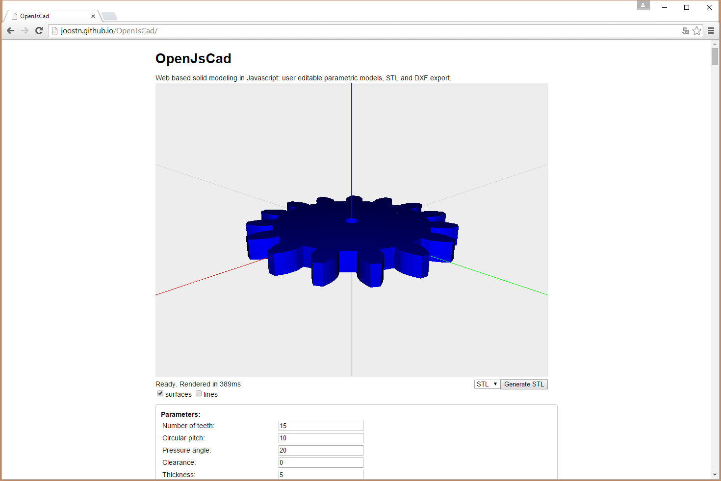
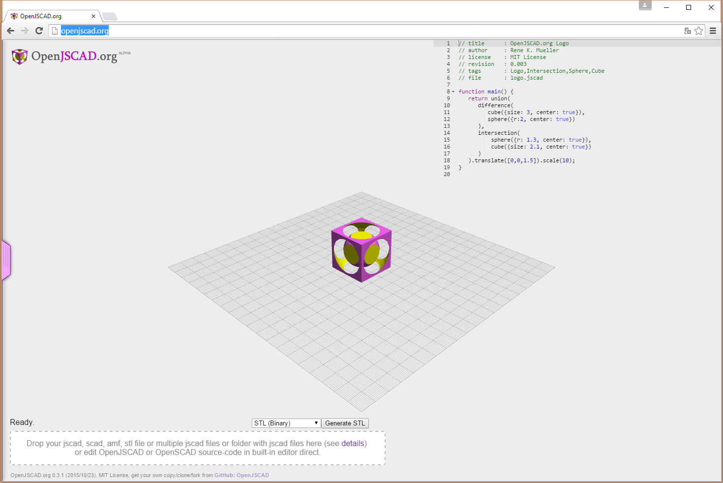
There is an alpha version of the software on-line at openjscad.org. It is is intended to become a Javascript based alternative to OpenSCAD, for 3D solid modeling.

openjscadorg

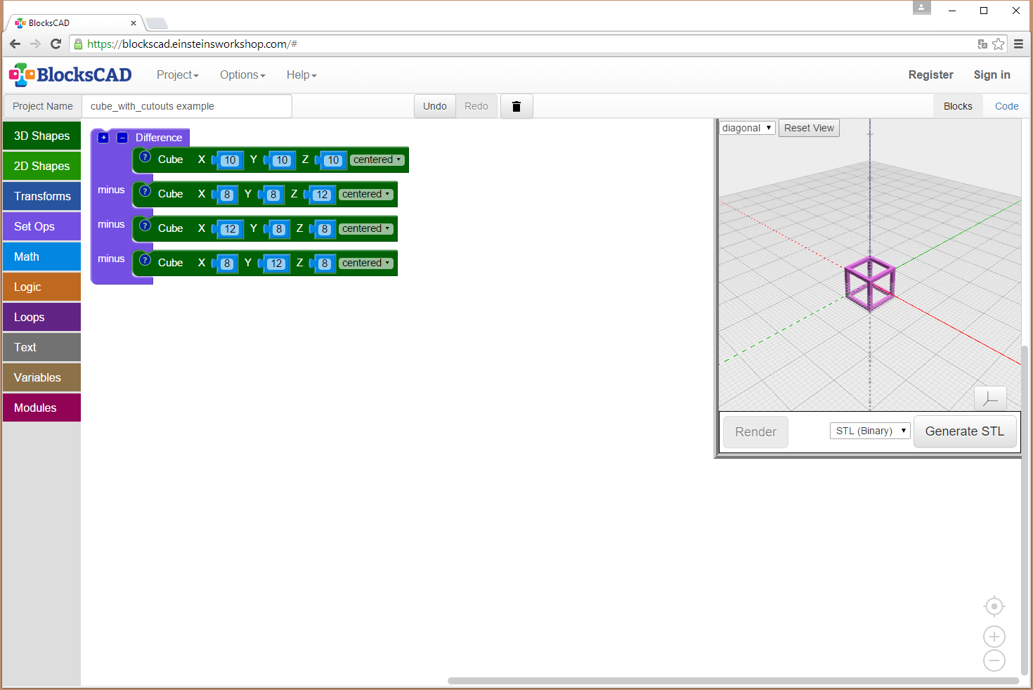
Does coding your 3D objects, while quite easy, still look too complicated to get started. There are also some alternatives that are even easier to get started. BlocksCAD is Browser-Based 3D Modeling that Teaches You CAD. MIT has come up with a new block-based educational tool called BlocksCAD. BlocksCAD is essentially Scratch combined with OpenSCAD and allows the user to use blocks (similar to Scratch) to build a 3D model. With this tool it’s possible to avoid model code syntax issues but still develop 3D models. You just make model by moving blocks, and get a 3D model and OpenSCAD code as result.  You can use the tool online at blockscad.einsteinsworkshop.com

blockscad


For ideas on other 3D modeling tools, check out also Scratch Your Itch for 3D Modeling with BeetleBlocks, Learn 3D Modeling in Your Browser and Development Tools of the Prop-Making World articles.


96 Comments

  1. Tomi Engdahl says:

    Highly Configurable Open Source Microscope Cooked Up In FreeCAD
    https://hackaday.com/2021/09/09/highly-configurable-open-source-microscope-cooked-up-in-freecad/

    What do you get when you cross a day job as a Medical Histopathologist with an interest in 3D printing and programming? You get a fully-baked Open Source microscope, specifically the Portable Upgradeable Modular Affordable (or PUMA), that’s what. And this is no toy microscope. By combining a sprinkle of off-the-shelf electronics available from pretty much anywhere, a pound or two of filament, and a dash of high quality optical parts, PUMA cooks up quite possibly one of the best open source microscopy experiences we’ve ever tasted.

    GitHub user [TadPath] works as a medical pathologist and clearly knows a thing or two about what makes a great instrument, so it is a genuine joy for us to see this tasty project laid out in such a complete fashion. Many a time we’ve looked into an high-profile project, only to find a pile of STL files and some hard to source special parts. But not here. This is deliberately designed to be buildable by practically anyone with access to a 3D printer and an eBay account.

    The project is not currently certified for medical diagnostics use, but that is likely only a matter of money and time. The value for education and research (especially in developing nations) cannot really be overstated.

    https://github.com/TadPath/PUMA

    Reply
  2. Tomi Engdahl says:

    Planning Custom Aluminum Enclosures With OpenSCAD
    https://hackaday.com/2021/12/26/planning-custom-aluminum-enclosures-with-openscad/

    We’ve seen a number of projects over the years that let you create custom enclosures using OpenSCAD, and for good reason. The parametric CAD tool is ideal for generating 3D models based on user-adjustable variables, and if you leverage its integrated Customizer, producing a bespoke box is as easy as moving some sliders around. The resulting files get sent off to the 3D printer, and you’re set. But what if you’re looking for a custom enclosure that’s not so…plastic?

    In that case, AlClosure by [0xPIT] might be the answer. Rather than generating STL files intended for your 3D printer, the code is written to help you design an enclosure made from aluminum sheets. The top and bottom panels are intended to be cut from 1.5 mm – 2.5 mm sheets, while the sides are made from thicker 5 mm – 8 mm stock to accept a machined pocket that holds the front and rear inserts.

    https://github.com/0xPIT/AlClosure

    Reply
  3. Tomi Engdahl says:

    An OpenSCAD Library For All Your CNC Cutting Needs
    https://hackaday.com/2022/01/02/an-openscad-library-for-all-your-cnc-cutting-needs/

    While there’s always the edge case, there’s a strong likelihood that if you’re using OpenSCAD, you’re probably working on a CAD model that you intend to 3D print at some point. Of course that’s not to say this is all you can do in OpenSCAD, but it’s arguably what it does best. If you wanted to make artistic models, or maybe render what your new kitchen will look like, there are other tools better suited to such tasks.

    But thanks to lasercut.scad, a library that [Brendan Sleight] has been working on for the last several years, we might have to reconsider our preconceived dimensional notions. Instead of designing parts for 3D printing, his library is all about creating parts intended for subtractive manufacturing. Originally (as the name implies) it was geared towards laser cutting, but the project has since evolved to support CNC routers, vinyl cutters, and pretty much anything else that can follow a DXF file.

    https://github.com/bmsleight/lasercut

    Reply
  4. Tomi Engdahl says:

    CadQuery Comes Of Age
    https://hackaday.com/2022/02/04/cadquery-comes-of-age/

    Now, we know what some of you are going to say — “Oh man, not another programmatic CAD tool, what’s wrong with OpenSCAD?” — and you may be right, but maybe hold on a bit and take a look at this one, because we think that it’s now pretty awesome! OpenSCAD is great, we use it all the time round these parts, but it is a bit, you know, weird in places. Then along comes CadQuery, and blows it out of the water ease-of-use and functionality wise. Now, we’ve seen a few mentions of CadQuery over the years, and finally it’s become a full-blown toolset in its own right, complete with a graphical frontend/editor, CQ-editor. No odd dependencies on FreeCAD to be seen! That said, installing FreeCAD is not a bad thing either.

    What is CadQuery
    CadQuery is an intuitive, easy-to-use Python library for building parametric 3D CAD models
    https://cadquery.readthedocs.io/en/latest/intro.html

    CadQuery /
    CQ-editor
    https://github.com/CadQuery/CQ-editor

    CadQuery GUI editor based on PyQT supports Linux, Windows and Mac.

    Notable features

    OCCT based
    Graphical debugger for CadQuery scripts
    Step through script and watch how your model changes
    CadQuery object stack inspector
    Visual inspection of current workplane and selected items
    Insight into evolution of the model
    Export to various formats
    STL
    STEP

    Reply
  5. Tomi Engdahl says:

    Custom battery tray maker
    https://www.youtube.com/watch?v=jTG4UYkUH3k

    A handy 3D script and guide to adjusting the parameters to make a custom tray to store your batteries or other cylindrical objects in a compact manner.

    DIY custom battery storage trays
    https://www.youtube.com/watch?v=dPa_6s1Vmjc&t=0s

    A handy 3D script and guide to adjusting the parameters to make a custom tray to store your batteries or other cylindrical objects in a compact manner.

    Openscad is a very interesting piece of open source software that lets you create 3D objects with a raw scripting language, allowing complex results from very tight code.

    The script for this project is included at the bottom of this description. You literally just copy and paste it into the text box of openscad to adjust it as desired, and create your own custom STL file for your 3D printing system.

    The six variables you can adjust are:-
    Width – The number of battery cups wide.
    Height – The number of battery cups high.
    Depth – The depth of the battery cups.
    Diameter – The internal diameter of the cups – slightly wider than your battery.
    Thickness – The thickness of the cup walls.
    Base – The thickness of the base.

    When adjusting the values, be careful not to remove the “=” and “;” as they are part of the script.
    To see your changes quickly, press the box with two arrows.
    To build the final object press the box with an hourglass in it.
    To save your custom STL file press STL. (After building with the hourglass button.)

    The STL file can then be used with your preferred slicer (I use Cura) to make the gcode file for your choice of 3D printer.

    I recommend making a single test cup (1X1) to test sizes before making a bigger tray of them.
    You can also just choose a width and height of 1 to make a single large cup for other purposes.

    Here’s the openscad script. Copy and paste the text below into openscad to use it.

    //Custom battery tray – bigclivedotcom
    $fn=50;
    //You can adjust these variables.
    width=4; //number of horizontal cups
    height=4; //number of vertical cups
    depth=10; //internal depth of cups
    diameter=15; //diameter of cylinder AA=15 AAA=11
    thickness=1; //thickness of wall
    base=1; //thickness of cup bases
    //don’t adjust stuff below here
    columns=width-1;
    rows=height-1;
    wall=thickness*2;
    dia=diameter+thickness;
    cup=depth+base;
    difference(){
    union(){
    //main body
    for (x=[0:columns]){
    for (y=[0:rows]){
    translate([x*dia,y*dia,0])
    cylinder(h=cup,d=diameter+wall);
    }
    }
    }
    //hollow cores
    for (x=[0:columns]){
    for (y=[0:rows]){
    translate([x*dia,y*dia,base])
    cylinder(h=cup,d=diameter);
    }
    }

    Reply
  6. Tomi Engdahl says:

    Make Your Own Tabletop Game Organizers With Online Tool
    https://hackaday.com/2022/02/19/make-your-own-tabletop-game-organizers-with-online-tool/

    There is a vibrant cottage industry built around selling accessories to improve the storage and organization of tabletop games, but the more DIY-minded will definitely appreciate [Steve Genoud]’s deckinabox tool, which can create either 3D-printable designs, or ones more suited to folded paper or cardstock. Making your own organizer can be as satisfying as it is economical, and [Steve]’s tool aims to make customization simple and easy.

    The tool can also generate models for folded paper or cardstock.

    https://deckinabox.sgenoud.com/

    Reply
  7. Tomi Engdahl says:

    CAD Up Some Shoes, But Don’t Start From Scratch
    https://hackaday.com/2022/03/03/cad-up-some-shoes-but-dont-start-from-scratch/

    Nothing helps a project get off the ground better than a good set of resources, and that’s what led [DaveMakesStuff] to release his Digital Shoe Design Kit, which is a set of 3D models ready to customize into a basic running shoe.

    This is exactly what is needed for people who are interested in designing a custom shoe, but perhaps not interested in modeling every element entirely from scratch. [DaveMakesStuff]’s resources allows one to mix outsoles, midsoles, uppers, and other basic shoe elements into a finished model, ready to be resized or even 3D printed if desired. The files are all in stl format, but resizing stl files is trivial, and more advanced editing is possible with mesh sculpting programs like Blender.

    https://www.thingiverse.com/thing:5235672

    Reply
  8. Tomi Engdahl says:

    The Noble Effort To Put OpenSCAD In The Browser
    https://hackaday.com/2022/03/14/the-noble-effort-to-put-openscad-in-the-browser/

    In a world of CAD packages with arcane or unfriendly interfaces there’s a stand-out player that’s remarkable because it has no interface. OpenSCAD is a CAD package for coders, in which all design elements are created in a scripting language rather than graphically. It’s maybe not for everyone but it has a significant following, and its reach has been extended further as you can now run it from within a modern web browser.

    https://openscad.cloud/openscad/

    Reply
  9. Tomi Engdahl says:

    Animate Your Robot In Blender
    https://hackaday.com/2022/05/11/animate-your-robot-in-blender/

    You’ve built a robot crammed full of servos and now you settle down for the fun part, programming your new dancing animatronic bear! The pain in your life is just beginning. Imagine that you decide the dancing bear should raise it’s arm. If you simply set a servo position, the motor will slew into place as fast as it can. What you need is an animation, and preferably with smooth acceleration.

    You could work through all the math yourself. After half an hour of fiddling with the numbers, the bear is gracefully raising it’s arm like a one armed zombie. And then you realize that the bear has 34 more servos.

    Fortunately for everybody who’s done the above, there’s Blender. It’s all about creating smooth motion for animations and computer graphics. Making robot motion with Blender is, if not easy, at least tolerable. We made a sample project, a 3-axis robot arm to illustrate. It has a non-moving pedestal, rotating base, upper arm, and lower arm. We’ll be animating it first in Blender and then translating the file over to something we can use to drive the servos with a little script.

    Now, Blender is notorious for a difficult user interface. The good news is that, with revision 2.9, it moved to a much more normal interface. It still definitely is a large program, with 23 different editors and literally thousands of controls, but we’ll only be using a small subset to make our robot move.

    Here are the major steps to animating a robot:

    Make a ‘skeleton’ (armature) that matches your robot
    Rig the armature so that it moves like your robot and is convenient to animate
    Animate the armature
    Export the servo positions to your robot control program

    4 bone armature. Bones are octahedrons with ball at head and tail
    Robot Armature

    Generally, computer animations consist of an armature and then the mesh for the body that hangs on it. For a robot, we don’t need the mesh, just the armature, because we’re not making a movie. Still, the armature does need to match the hardware size. Import CAD files or build atop a photo or just measure the robot.

    Interacting

    This is great, but now we want our robot bear to grab a present. How will the robot interact with the outside world. The solution is inverse kinematics (IK). IK lets us say where we want the wrist, not where the shoulder and elbow joints are. So we added a ball named IK to the scene and added an IK constraint to the lowerarm to try to reach the ball.

    If you’re following along, move the sample timeline to frame 120, so the IK is on and you’re not messing up our animations.

    The robot wrist now is ‘grabbing’ the IK ball. In object mode, select the ball and use (g key) to ‘grab’ it. Drag to move the ball around. The robot neatly follows along, and the joints set themselves to do what’s needed. Much more convenient.

    If you want to poke around in the IK constraint, its home is lowerarm. In pose mode, select lowerarm and the bone constraints tab in the object properties editor on right. The IK constraint lives here.

    Animation Time

    We’re now ready to animate. 10 FPS is fine for most robots — set this in Render Properties. We just put all the animations one after the other in the timeline, and grab the slice we want, so maybe ‘bear chuckles’ is frame 50 to 70.

    Back when we were moving the bear arm by typing in numbers, we had to do every frame. Thankfully not needed now. We only have to pose the robot on enough frames to get the behavior we want. These are keyframes. Blender does the frames in between.

    By default Blender adds the ease in and ease out, so the servos accelerate smoothly. You can select the IK ball and check the ‘Graph Editor’ if you want to see the curves.

    From Animation to Robot

    We’re ready to move our animation to our robot control program. There’s a nifty hack for this. The de facto standard for computer animation files is ‘BioVision Hierarchical’ format (bvh). Blender can export it, though you might need to enable the plugin and select the armature.

    The actual numbers are the Blender joint positions in degrees, so all that’s left to do is set the servos once every frame time, and your animation will play out in reality.

    Don’t forget, if you play animations one after the other, that the second animation needs to start with the robot where the last one left it. And remember that just because you ask for a servo position, you may not get it. If you know your robot moves slowly, asking for snappy action will lose position control. Blender doesn’t know.

    Finally, we’d note that the ‘robot’ need not be a robot. Anything that needs scripted animation can be treated this way.

    Of course, that’s not all there is to making an intelligent robot assistant.

    Reply
  10. Tomi Engdahl says:

    DIY SBC cases and SBC Case Builder tool based on OpenSCAD
    https://www.cnx-software.com/2022/04/30/diy-sbc-cases-and-sbc-case-builder-tool-based-on-openscad/

    Since you can’t always rely on single board computer (SBC) vendors to provide a case to match your needs, some went the DIY route. Willy Tarreau designed some laser-cut enclosures with Inkscape for various SBCs, while hominoids went a step further by developing the “SBC Case Builder” tool to automatically generate various types of 3D printable enclosures using OpenSCAD.

    Willy designed five similar enclosures for Khadas VIM3/VIM3L, FriendlyELEC NanoPi Fire3, SolidRun Clearfog Base networking SBC, Libre Computer AML-S805X-AC (aka “La Frite”), and AAEON UP Board.

    Reply
  11. Tomi Engdahl says:

    https://hackaday.com/2022/08/06/learning-by-playing/

    The kids didn’t even flinch at having to learn a new 3D modelling tool, and the parallels to what they were already comfortable doing in Minecraft were obvious to them. My son came home and told me how much easier it was to do your 3D modelling in “this other Minecraft” – he meant TinkerCAD – because you don’t need to build everything out of single blocks. He thought he was playing games, but he’d secretly used his first CAD tool. Nice trick!

    Reply
  12. Tomi Engdahl says:

    enSweepen [gd0096]
    Procedural and parametric, node-based CAD for 3D modelling with sketches.
    https://hackaday.io/project/184196-ensweepen-gd0096

    Reply
  13. Tomi Engdahl says:

    Local Simulation Feature To Be Removed From All Autodesk Fusion 360 Versions
    https://hackaday.com/2022/08/12/local-simulation-feature-to-be-removed-from-all-autodesk-fusion-360-versions/

    The removal of features from Autodesk products would appear to be turning into something of a routine at this point, with the announced removal of local simulations the latest in this series. Previously Autodesk had severely cut down the features available with a Personal Use license, but these latest changes (effective September 6) affect even paying customers, no matter which tier.

    While previously executed local simulations on designs will remain accessible, any updates to these simulations, as well as any new simulations will have to use Autodesk’s cloud-based solver. This includes the linear stress, modal frequencies, thermal, and thermal stress simulation types, with each type of simulation study costing a number of Cloud Tokens.

    Solving a linear simulation should initially cost 0 tokens, but the other types between 3 – 6 tokens, with the exact cost per token likely to vary per region. This means that instead of solving simulations for free on one’s own hardware, the only option in a matter of weeks will be solely through Autodesk’s cloud-based offerings.

    Tokens for Fusion 360 Simulation studies
    https://help.autodesk.com/view/fusion360/ENU/?guid=GUID-97268379-A0C4-4426-8929-2FB3F3FB439C

    The cost of running Linear Static Stress analyses are included as part of your Fusion 360 subscription. You can solve all other studies in the cloud, on a pay-per-use basis, using tokens.

    Reply
  14. Tomi Engdahl says:

    #tech3d #autodesk #software
    free software?! WTF is going on at autodesk?!
    https://www.youtube.com/watch?v=EbJyQExIVDo

    A new free personal license from Autodesk, starting small going hopefully big.
    Beginning with Autodesk Alias and Autodesk Vred Professional, anyone can download and use these tools for free for 1 year using the new Personal Learning Edition license.

    Explanation blog:
    https://blogs.autodesk.com/design-studio/2022/10/17/learn-alias-and-vred-at-home-autodesk-releases-alias-and-vred-learning-editions/

    Reply
  15. Tomi Engdahl says:

    SBC Case Builder 2.0 released with GUI
    https://www.cnx-software.com/2022/10/12/sbc-case-builder-2-0-released-with-gui/

    SBC Case Builder 2.0 tool to create enclosures for single board computers has been released with a customizer graphical user interface, additional cases & SBCs, support for variable height standoffs, and more.

    We wrote about the SBC Case Builder tool to easily generate various types of 3D printable enclosures using OpenSCAD earlier this year. The SBC Model Framework used in the solution was focused on ODROID boards, and you had to type the parameters in a configuration file. SBC Case Builder 2.0 software changes that with a convenient-to-use graphical interface allowing for the dynamic adjustment of any of the case attributes.

    https://www.cnx-software.com/2022/04/30/diy-sbc-cases-and-sbc-case-builder-tool-based-on-openscad/

    Reply
  16. Tomi Engdahl says:

    3D for everyone? Nvidia’s Magic3D can generate 3D models from text
    New AI aims to democratize 3D content creation, no modeling skills required.
    https://arstechnica.com/information-technology/2022/11/nvidias-magic3d-creates-3d-models-from-written-descriptions-thanks-to-ai/

    Reply
  17. Tomi Engdahl says:

    GhostSCAD: Marrying OpenSCAD And Golang
    https://hackaday.com/2023/02/12/ghostscad-marrying-openscad-and-golang/

    It’s been at least a couple of months since we’ve seen a different 3D modeling language project, so here’s [Lukasz Janyst] with GhostSCAD: a take on creating OpenSCAD models, using the Go language as the front end, bringing all the delights this modern modular language has to offer (and a few of its own idiosyncrasies.) As [Lukasz] says in the blog, from a programmer’s viewpoint, openSCAD has a number of failings that make it not necessarily hard, just kinda annoying to work with, due to the way the geometry tree works. The OpenSCAD way of working ends up with the programmer requiring knowledge of the internal workings of sub-modules, in order to work at the top level (assembly) which is not an ideal situation from a code reuse perspective.

    https://jany.st/post/2022-04-04-ghostscad-marrying-openscad-and-golang.html

    Reply
  18. Tomi Engdahl says:

    Tinkercad Gets A Move On
    https://hackaday.com/2023/04/13/tinkercad-gets-a-move-on/

    Going to the movies is an experience. But how popular do you think they’d be if you went in, bought your popcorn, picked your seat, and the curtain would rise on a large still photograph? Probably not a great business model. If a picture is worth 1,000 words, then a video is worth at least a million, and that’s why we thought it was awesome that Tinkercad now has a physics simulator built right in.

    https://www.tinkercad.com/blog/tinkercad-sim-lab

    Reply
  19. Tomi Engdahl says:

    Parametric Design With Tinkercad
    https://hackaday.com/2023/04/26/parametric-design-with-tinkercad/

    Tinkercad is like the hamburger helper of 3D design. You hate to admit you use it, and you know you should put in more effort, but — darn it — it’s easy, and it tastes pretty good. While I use a number of CAD programs for serious work, sometimes, when I just want a little widget like a flange for my laser cutter’s exhaust, it is just easier to do it in a few minutes with Tinkercad. However, I heard someone complaining the other day that it wasn’t of any use anymore because they took away custom shape generators. That statement is only partially true. Codeblocks allow you to easily create custom parametric items for use in Tinkercad.

    There was a time when you could write Javascript to create custom shapes, and it is true that they removed that feature. However, they replaced it with Codeblocks which is much easier to use for their target audience — young students — and still very powerful.

    The Third Thinkercad Thing

    When you go to the Tinkercad website, you probably notice there are two extra selections in addition to 3D design. One is Circuits which lets you build and simulate simple electronic circuits that include Arduinos and other items. The other item is Codeblocks. You might assume that is a way to program the Arduinos in the simulation, but that’s not what it is. It turns out there is something very similar in the circuit simulator for that purpose. But Codeblocks is for creating new parts for use either on their own or as new parts within Tinkercad.

    If you are familiar with OpenSCAD, the idea is that it is sort of Scratch and OpenSCAD merged together. Sort of. There are a few things that are, perhaps, less than ideal, but overall, it works well. The block language doesn’t have some things like if/then/else statements. Handling variables is a bit clunky, but possible. The way you produce reusable parts is very wacky, but once you get used to it, it isn’t bad.

    To Tinkercad

    If all you needed was the plate, then you are ready to go. Press Export, and you can create an STL, OBJ, or SVG. However, one of the other options is “Shape.” That’s how you get it into your Tinkercad tool palette. You can give the part a name, a description, and a color. Optionally, you can lock the part size so no one can rescale it in the normal Tinkercad editor.

    Once you finish the export, the part will appear in the normal shape library under “Your Creations.” You can place it like any other Tinerkcad shape, and if you allowed it during the export, you could resize it there.

    So while the custom shape generator is gone, its spirit lives on in Codeblocks. Is it perfect? No. Honestly, if I were just going to do the whole part like this, I’d probably turn to OpenSCAD. But if you need to support custom shapes in Tinkercad, Codeblocks is perfectly serviceable.

    Reply
  20. Tomi Engdahl says:

    3D Design With Text-Based AI
    https://hackaday.com/2023/05/12/3d-design-with-text-based-ai/

    Generative AI is the new thing right now, proving to be a useful tool both for professional programmers, writers of high school essays and all kinds of other applications in between. It’s also been shown to be effective in generating images, as the DALL-E program has demonstrated with its impressive image-creating abilities. It should surprise no one as this type of AI continues to make in-roads into other areas, this time with a program from OpenAI called Shap-E which can render 3D images.

    Like most of OpenAI’s offerings, this takes plain language as its input and can generate relatively simple 3D models with this text. The examples given by OpenAI include some bizarre models using text prompts such as a chair shaped like an avocado or an airplane that looks like a banana. It can generate textured meshes and neural radiance fields, both of which have various advantages when it comes to available computing power, training methods, and other considerations. The 3D models that it is able to generate have a Super Nintendo-style feel to them but we can only expect this technology to grow exponentially like other AI has been doing lately.

    https://www.digitaltrends.com/computing/openai-shap-e-dall-e-for-3d/

    he Shap-E program is available for anyone to use from this GitHub page.
    https://github.com/openai/shap-e/

    Reply
  21. Tomi Engdahl says:

    FreeCAD Beginners tutorial: practical exercise 51 – STUDYCADCAM – MultiTransform tool
    https://www.youtube.com/watch?v=dS0D0vZZOes

    Hello, in this video i show you how to design this piece in FreeCAD using basic features like MultiTransform tool in PartDesign workbench.

    Reply
  22. Tomi Engdahl says:

    FreeCAD Is Simple, According To This Tutorial
    https://hackaday.com/2023/07/05/freecad-is-simple-according-to-this-tutorial/

    Remember learning to tie your shoes or ride a bike? Like many things, that’s easy once you know how to do it, but seems impossible before you learn. [NovaSpirit] asserts that Freecad is simple, and provides a simple walkthrough to create a part in the video below.

    If this were riding a bike, this tutorial would be akin to watching someone ride a bike to pick up tips. You’d probably still want to have someone explain details to you before you attempt it yourself.

    Freecad’s constraint system can be confusing, and [NovaSpirit] deliberately sticks to very simple ways to use it. However, once you get your feet wet, you’ll want to explore more sophisticated constraints. For example, instead of just plugging in measurements for how far away things are from the center is a problem if the size of the part ever changes since you have to remember to change it everywhere. With proper constraints, you would simply adjust the size of the part, and everything would move to the proper place.

    Learning FreeCad with These Basic Steps
    https://www.youtube.com/watch?v=rglvJH9z5ng

    Reply
  23. Tomi Engdahl says:

    8 Best TinkerCAD Alternatives and Competitors of 2023
    https://www.selfcad.com/blog/8-best-tinkercad-alternatives

    Autodesk’s TinkerCAD is a popular 3D modeling program well-suited for beginners, as it provides a good entrance point into the world of 3D modeling. It’s still a viable option for creating fantastic 3D drawings and simple 3D designs. However, you may want to use another similar program for any reason. For example, if you would like to prepare complex and complex 3D models you will need to look for a powerful 3D modeling software as TinkerCAD can’t handle such designs. Also, if you don’t want to design models only online, you will need a program that can run on both windows and Mac and not only in the browser. There are various reasons why you might be seeking TinkerCAD alternatives, and in this article, you will get to know the best TinkerCAD alternatives of 2023. But before that, we can look at the advantages and disadvantages of TinkerCAD.

    Reply
  24. Tomi Engdahl says:

    https://www.facebook.com/share/p/f3DJgsnXxTHuanVd/

    Löysin loistavan työkalun 3D printtausten suunnitteluun. Sopii mun päälleni joka mielummin ”ohjelmoi” kuin pyörittelee hiirellä ja kliksuttelee 3D CAD objektia: https://openscad.org

    Sitä käyttäen on tehty tämä hieno työkalu suojalaatikon kustomointiin piirilevyn tai muun omien mittojen projektin ympärille https://github.com/mrWheel/YAPP_Box. Aloitetaan kertomalla koteloon tulevan kappaleen mitat, sitten kootaan kotelo siihen ympärille. Koordinaatiston
    kotelon aukoille yms. voi valita: defaulttina piirilevyn koordinaatisto. Luetellaan lista koordinaateista joihin halutaan aukot, ruuvi-insertit, standoffit, …

    Piffasin tekijälle kahvit PayPalillä.

    Tämä bloggaus kertoo YAPPista hyvin:
    https://willem.aandewiel.nl/index.php/2022/01/02/yet-another-parametric-projectbox-generator/

    Hiukan samaa logiikkaa rakensin aikanaan useamman päivän itse Fusion360:seen. Mut tää on paljon parempi, ja tähän on kertyneenä paljon kokemusta mm. mekaniikan mitoituksista.

    Reply
  25. Tomi Engdahl says:

    https://qcad.org/en/

    QCAD is a free, open source application for computer aided drafting (CAD) in two dimensions (2D). With QCAD you can create technical drawings such as plans for buildings, interiors, mechanical parts or schematics and diagrams. QCAD works on Windows, macOS and Linux. The source code of QCAD is released under the GPL version 3 (GPLv3), a popular Open Source license.

    Reply

Leave a Comment

Your email address will not be published. Required fields are marked *

*

*