A valve amplifier or tube amplifier is a type of electronic amplifier that uses vacuum tubes to increase the amplitude or power of a signal. In audio applications, valves continue to be highly desired by most professional users, particularly in recording studios’ equipment and guitar amplifiers. Among stereo enthusiasts, there is a subgroup of audio buffs who advocate the use of tube amplifiers for home listening; they argue that tube amplifiers produce a “warmer” or more “natural” valve sound. Tube sound (or valve sound) is the characteristic sound associated with a vacuum tube-based audio amplifier.
Before the rise of the transistor in the 1950s, all amps used vacuum tubes. Still the audible significance of tube amplification on audio signals is a subject of continuing debate among audio enthusiasts. Audiophiles disagree on the relative merits of tube vs solid state amplification. Tube amplifiers have retained a loyal following amongst some audiophiles and musicians. Some musiciansprefer the distortion characteristics of tubes over transistors for electric guitar, bass, and other instrument amplifiers.
Today tubes are the incandescent light bulb of the audio world: an older, relatively inefficient technology that consumes a good deal of energy to output a modest amount of power. For power amplifiers solid state designs can be manufactured without output transformers and are therefore immune to speaker-dependent impedance mismatches and transforer effects. I have been long the person who has usef transistors for hifi applications and considered they to be better for hifi amplifiers.
Tubes have their place in audio processing where you want to add to the sound the “warm tube distortion” sound (for example in guitar amplifiers). For preamplifer use tubes can work well. To get the idea of tube sound and how tube preamps works, I got this cheap kit for experimenting: AC12V/1A Stereo 2.0 Pre Amplifier Headphone Module Amplifier Buffer Board. It is a preamplifer that is suitable for conntrolling volume of line level audio signals (attenuate or amplify) and maybe add some magic tube sound to audio. Cheap way though of experiencing ‘tube sound’!
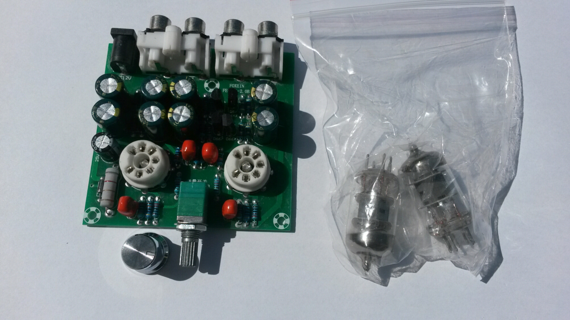
Type: FE-6J1-2.0B
Channel type: 2.0/ stereo
Power input: AC12V 1A / 5.5*2.5 plug
Knob function: Power switch / volume control
Size: 76 x 74 x 20mm
Pre-amp tube diameter: 18mm
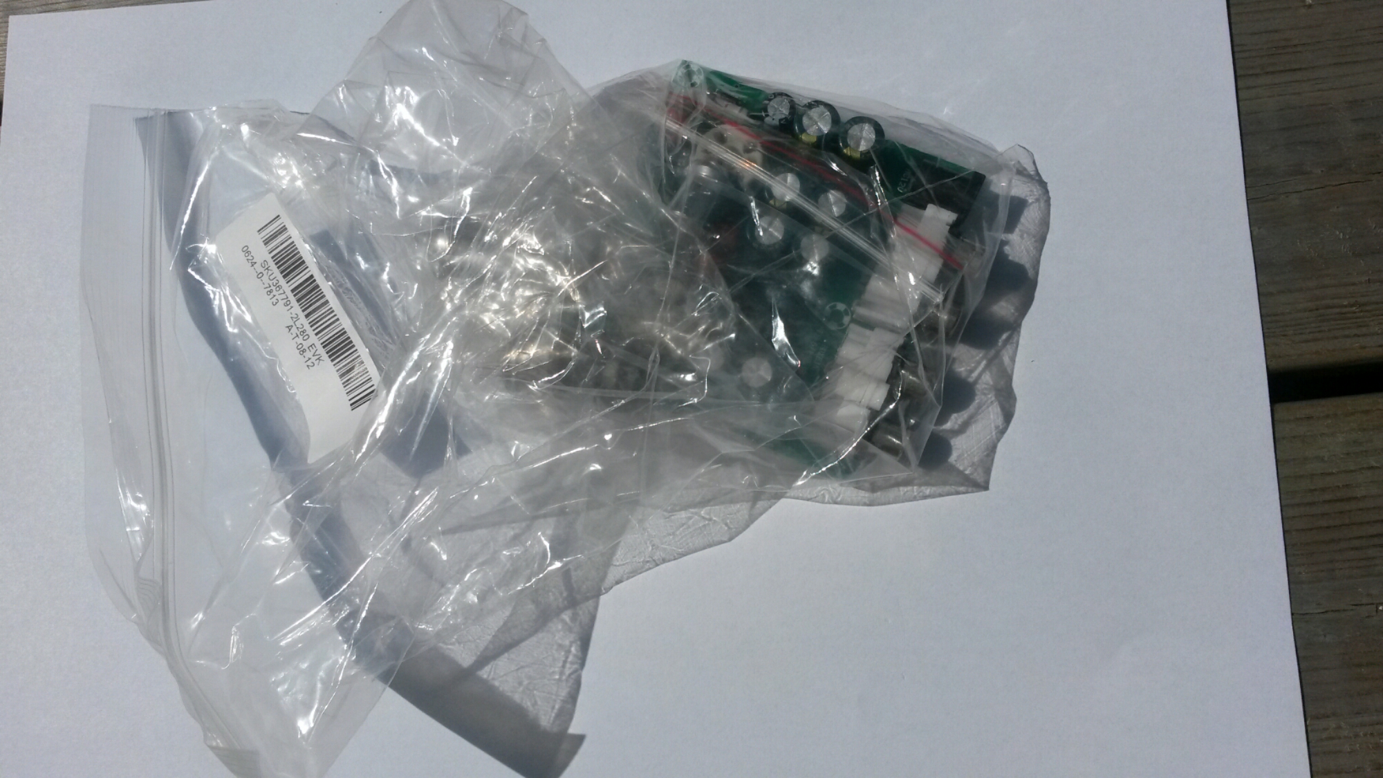
Everything was packed to a plastic bags.
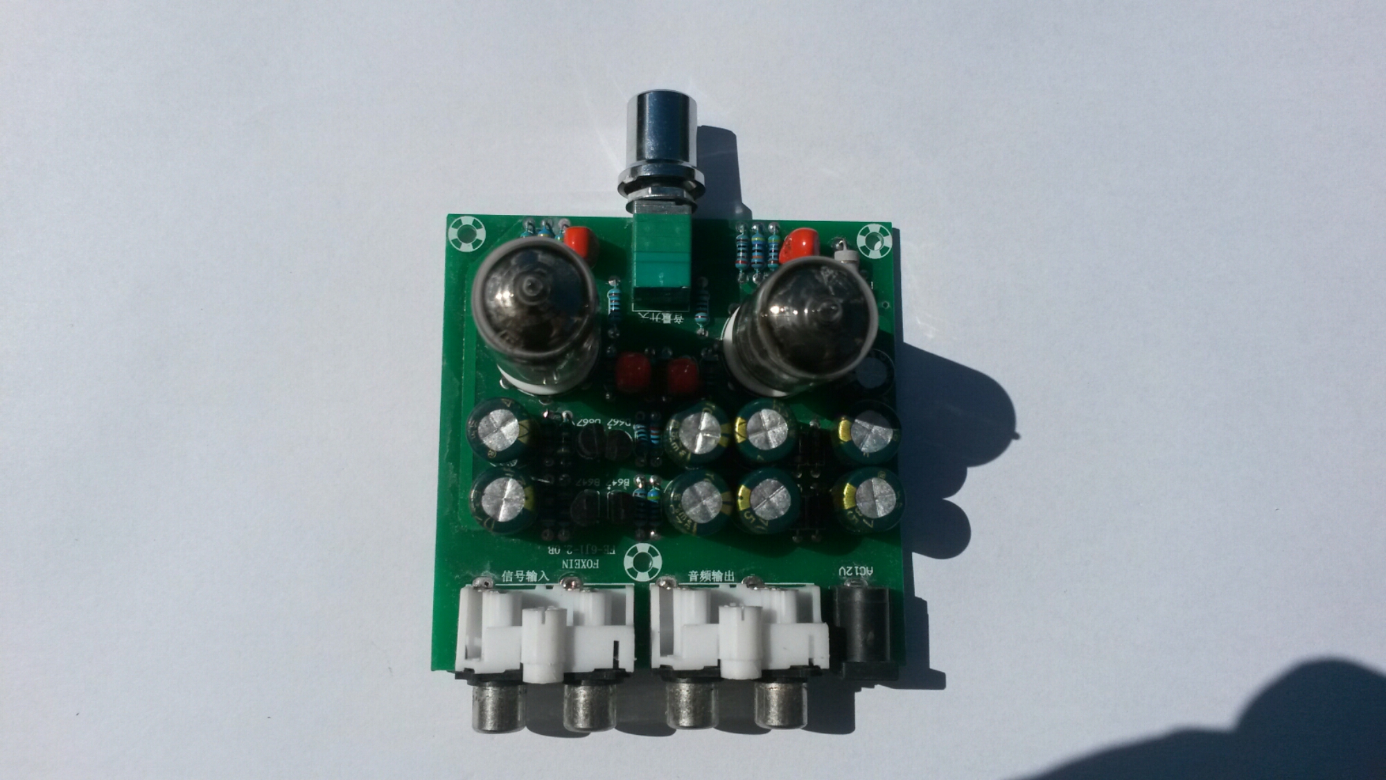
There seem to be some small LEDs in the center of tube sockers. Those are blue LEDs that make the tubes to glow in blue color.
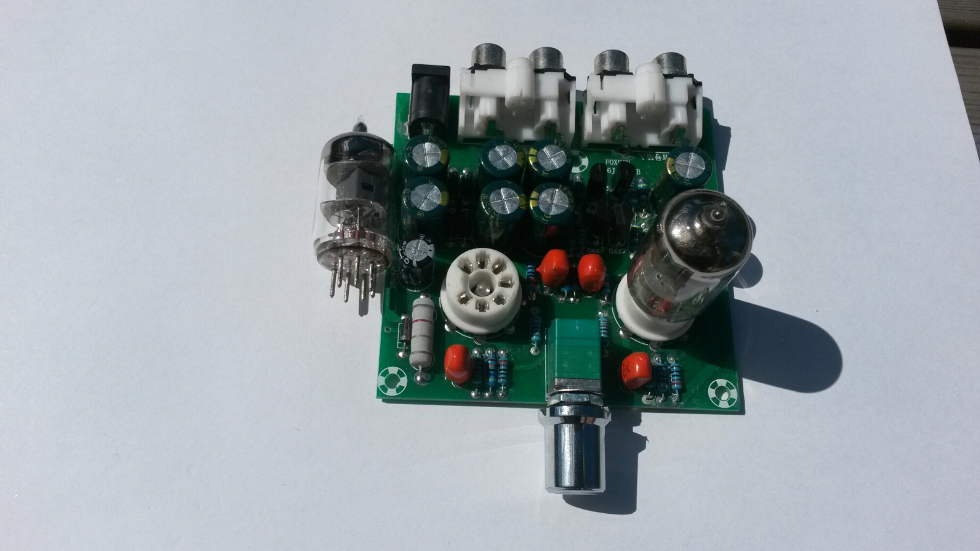
One tube installed.
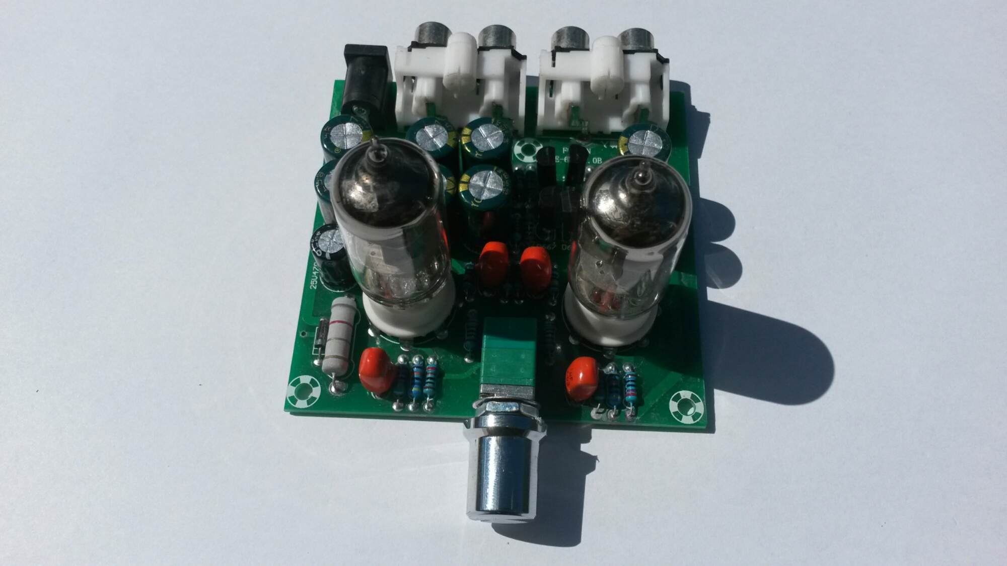
Two tubes installed.
The volume control in this board is combined volume control and power switch: The knob rotates counterclockwise to reduce the volume, when the volume to the hour, continues to rotate, until the “tick” sound, then power off, lights out.
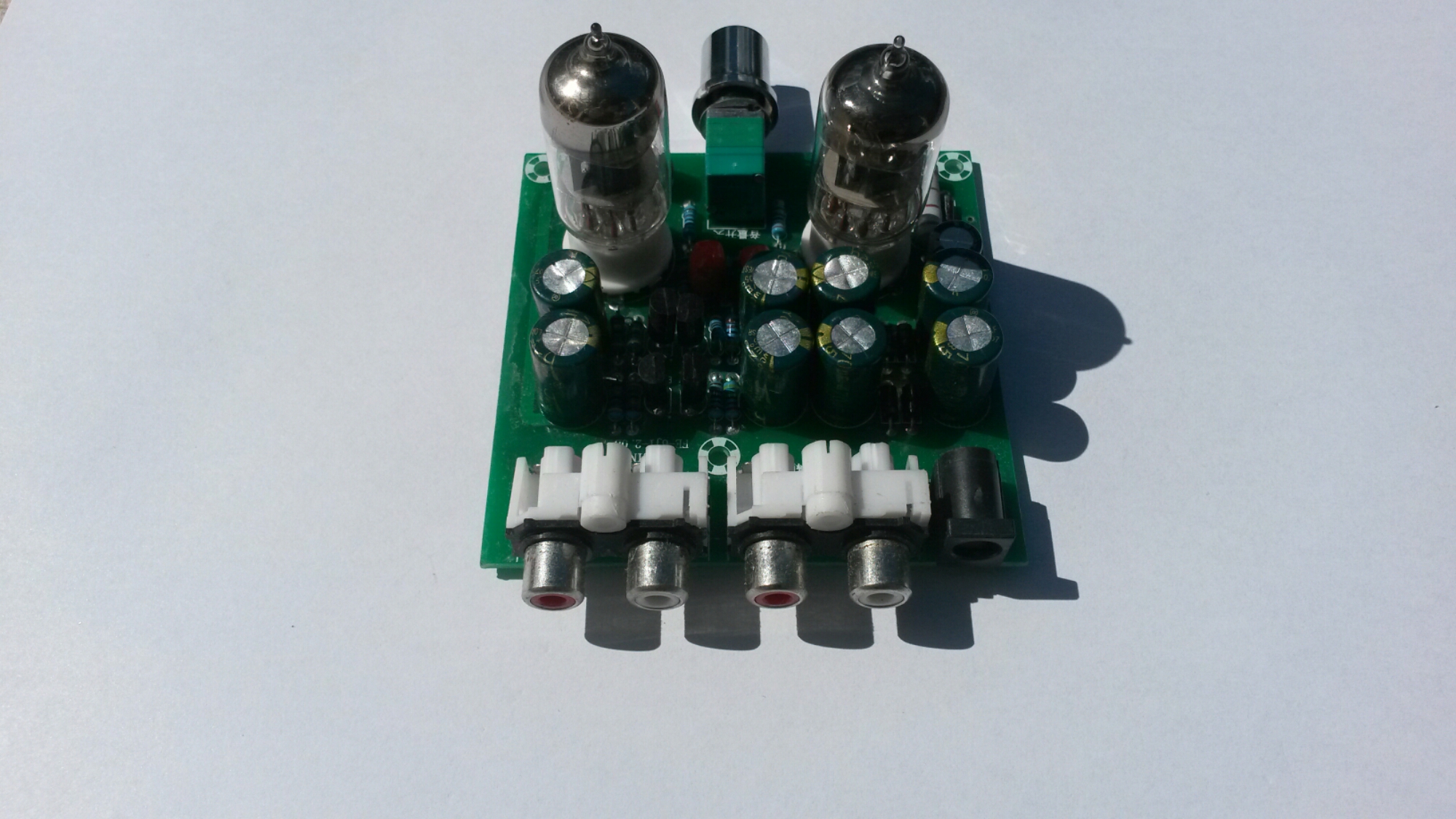
A look to the connectors…
On the left side: Audio signal input terminals that can be connected to mobile phones, computers, MP3, MP4, and other music player.
On the right side: The output terminal of the audio signal can be connected to an audio signal input terminal of a power amplifier and a power amplifier board. And next to them power input (12V AC 1A).
When I powered the amplifier, it did what it promised. It worked OK as a preamplifier.
Voltage amplification can be controlled from zero to around 6 times (around 15 dB).
The output worked on testing well to over 2Vpp input signal amplitudes at maximum amplitude without noticeable distortion on oscilloscope screen starting to appear.
The signal output impedance is around 3 kilo-ohms. That works well as line level signal preamplifier that drives power amplifier. This circuit is not headphone amplifier that drives headphones (if you thing if that from product name), it would would be pretty non-ideal headphone amplifier for low impedance headphones.
Does what it describes as preamplifier for audio signals. It sounds good, but I can’t find it to be adding any magic “tube sound” to the audio. The circuit adds some slight huming though (at more than about 1/3rd volume).
Note on powering: you need an (not DC) 12V plugpack or transformer. The kit says it needs 12V 1A power supply, so that what I used (I did not measure the actual power this circuit takes).
Ti get better idea how this circuit amplifier works, a circuit diagram would be nice. With some Googling I found that there are several pages that tell about this or very similar tube amplifiers:
https://www.circuitlab.com/circuit/9vnehk/fever-6j1-tube-pre-amp-circuit/
http://www.diyaudio.com/forums/tubes-valves/286349-6j1-tube-buffer-circuit-diagram.html
The best circuit diagram I could found was this at https://www.circuitlab.com/circuit/9vnehk/fever-6j1-tube-pre-amp-circuit/
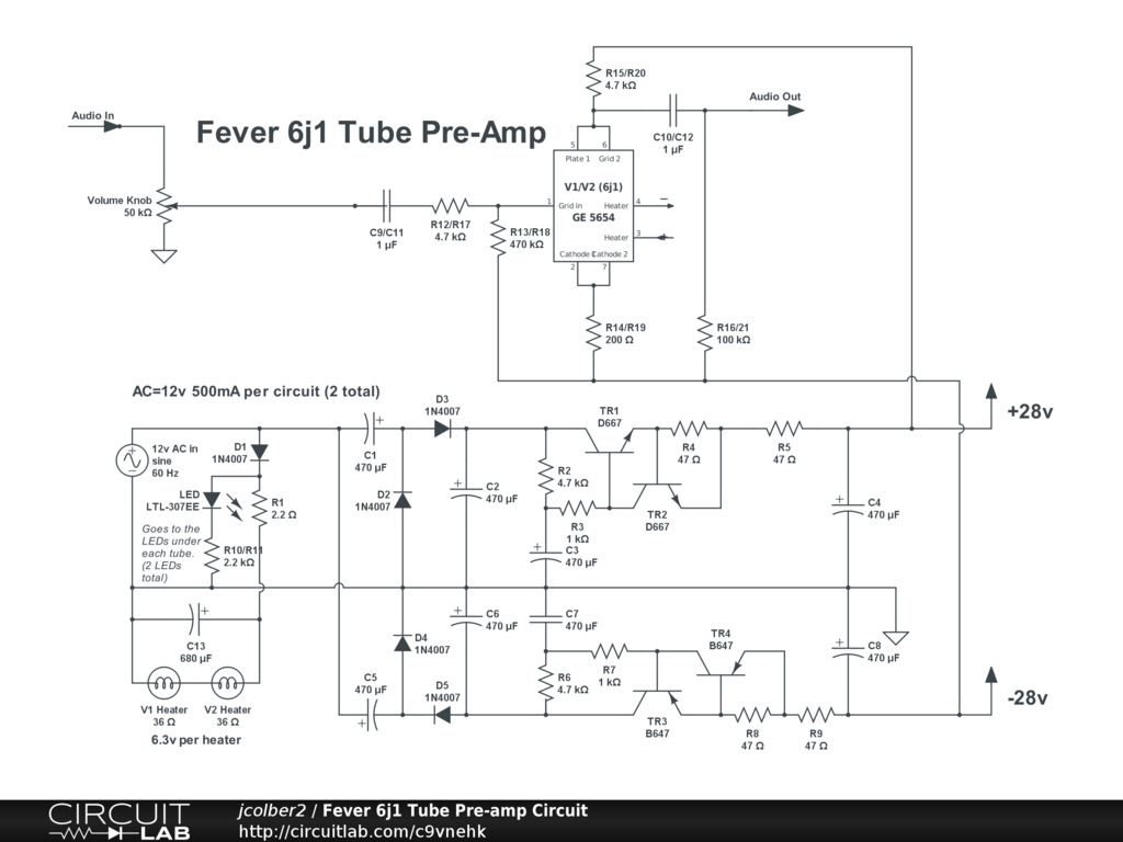
It seems to be mostly correct (shows only one channel), but has some small details that do not seem to be correct (for example connection of resistor on amplifier output should be connected to ground and not -28V). By the way the circuit diagram can be edited at https://www.circuitlab.com/editor/#?id=9vnehk
As you can see in the circuit diagram the power supply part converts the 12V AC input to +28V and -28V power rails that are used to power the tube. This means that the tube is run at 56V voltage (which is quite low voltage for an audio tube circuit, they typically operate at 100-300V voltage depending on tube type). This 56V voltage is good for safety – it does not hurt too much if you accidentally come in contact with this voltage when you test the board before putting it to case.
The power supply circuit consists of voltage multiplier + rectifier circuit followed with filter capacitors, some transistor circuitry (emitter follower with current limiting, somewhat resembles gyrator circuit) and more filter capacitors.
The tube heaters are directly powered from input 12V AC (two 6.3V heating coils in series can be powered from 12V AC).
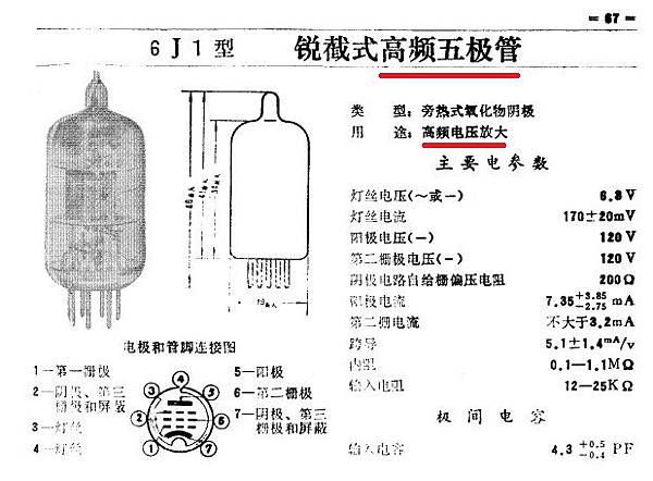
Information on the 6J1 tube used can be found at http://www.radiomuseum.org/tubes/tube_6j1.html and http://greatsound168.pixnet.net/blog/post/254453398-%E4%BA%8C%E5%8F%B06j1%E7%B7%A9%E8%A1%9D%E7%B4%9A%E7%9A%84%E5%88%86%E6%9E%90
Another preamp circuit using 6J1 tube at http://www.yunwt.net/1mydiy/qt14.htm
The basic design of this AC12V/1A Stereo 2.0 Pre Amplifier Headphone Module Amplifier Buffer Board seems to be sensible. If I had designd this I would maybe had designed few things slightly differently (for example power supply filtering and maybe tube heating) – that could have maybe reduced the slight mains humming on the output. Anyways as it isC12V/1A Stereo 2.0 Pre Amplifier Headphone Module Amplifier Buffer Board seems to be good quality cheap tube preamplifier.
276 Comments
Tomi Engdahl says:
Some tube amplifier articles (in Finnish):
http://audiovideo.fi/opas/putkivahvistinrakennusohje-se84-brachycera-osa-1
http://audiovideo.fi/opas/putkivahvistinrakennusohje-se84-brachyera-osa-2
Tomi Engdahl says:
The technical specifications said that the module uses 12V AC 1A power supply.
I tested my premap with current meter, and found out that it takes around 200 mA current from 12V AC 50 Hz power source.
Tomi Engdahl says:
Now is the Golden Age of Artisanal, Non-Traditional Tube Amps
http://hackaday.com/2016/09/24/now-is-the-golden-age-of-artisanal-non-traditional-tube-amps/
Earlier in the month, [Elliot Williams] quipped that it had been far too long since we saw a VFD-based amplifier build. Well, that dry spell is over. This week, [kodera2t] started showing off his design for a VFD headphone amp.
Here’s the thing, this isn’t using old surplus vacuum fluorescent displays. This is actually a new part. We first covered it about 18 months ago when Korg and Noritake announced the NuTube. t’s the VFD form factor you would find in old stereo and lab equipment, but housed in the familiar glass case is a triode specifically designed for that purpose.
Amplifier project by Nutube, a new vacuum tube!
You know VFD, but may not know this VFD. It can amplify signal!! Yes, it is a TRIODE!!
https://hackaday.io/project/15023-amplifier-project-by-nutube-a-new-vacuum-tube
VFD is well known as digit display but not a amplifying device. A Japanese company Noritake and KORG made a incredible device by VFD technology. It looks like VFD but it works as a TRIODE.
Most of vacuum tune requires high voltage but VFD is just around 12V. Moreover it is quite compact compared to general vacuum tube!
Tubes on a Chip
http://hackaday.com/2015/02/02/tubes-on-a-chip/
For 40 years, there really haven’t been many advances in tube technology. Now, at last, there’s something new.
The Nutube 6P1, as this curious invention is called, is a full triode or half of a 12ax7 you’ll find in just about every tube amp ever. Unlike the 12ax7, it consumes 2% of the power required of a normal tube, is 30% of the size of the normal tube, and lasts for 30,000 hours.
This new tube-chip thing was brought to life by Korg, makers of fine musical equipment and Noritake Co., manufacturers of vacuum fluorescent displays. There’s no word on what these tubes will be used in and there’s no data sheet.
Tomi Engdahl says:
Fleming patents vacuum tube, November 16, 1904
http://www.edn.com/electronics-blogs/edn-moments/4401607/Fleming-patents-vacuum-tube–November-16–1904?_mc=NL_EDN_EDT_EDN_today_20161116&cid=NL_EDN_EDT_EDN_today_20161116&elqTrackId=52a02361c21142d7be1f11f0b95ed9d3&elq=2cc3a21a761e407391818a97c2957f71&elqaid=34807&elqat=1&elqCampaignId=30382
English engineer John Ambrose Fleming received a patent for the thermionic valve, better known as the vacuum tube, on November 16, 1904.
The two-electrode vacuum-tube rectifier, which Fleming called the oscillation valve, and some peers called the Fleming valve, was a major breakthrough. However, whether the breakthrough actually belonged to Fleming was debated in and out of court.
The United States Supreme Court eventually invalidated the patent because of an improper disclaimer and maintained that the technology in the patent was known art when filed.
Even still, Fleming continued to work on his diode and saw its use in radio receivers and radars for many decades afterward, until it was superseded by solid state electronic technology.
Tomi Engdahl says:
Vintage Tube Radio Restorations
http://hackaday.com/2016/11/17/vintage-tube-radio-restorations/
Tomi Engdahl says:
Dave reverse engineers the XuanZu X2-U808 Hi-Fi Headphone Amplifier to see if the valves actually do anything.
EEVblog #837 – Reverse Engineering A Valve Headphone Amplifier
https://www.youtube.com/watch?v=coSt5HWRvv4
Tomi Engdahl says:
Another valve amplifier design:
The Muffsy BSTRD – Valve Preamp
https://hackaday.io/project/16944-the-muffsy-bstrd-valve-preamp
An open source Class-A valve preamplifier and regulated PSU, complete with Eagle project files and detailed Bill of Materials
Tomi Engdahl says:
The Muffsy BSTRD – Valve Preamp
https://hackaday.io/project/16944-the-muffsy-bstrd-valve-preamp
An open source Class-A valve preamplifier and regulated PSU, complete with Eagle project files and detailed Bill of Materials
View Gallery
1.5k 0 1 3
Team (1)
skrodahl
Join this project’s team
completed project
hardware
PREAMP MUFFSY Valve tube eagle files gerbers hifi BSTRD The bastard Ny Elektronik psu POWERSUPPLY TL783 LM317 6J5 6S2S
This project is submitted for
Hackaday.com Tip Line
This project was created on 10/31/2016 and last updated 2 minutes ago.
Description
The BSTRD iis a simple Class-A valve preamplifier, complete with Eagle project files in the files area of this project. The preamp has been built and tested, so it’s perfectly safe to order the PCBs from the fab house of your choice.
The project is fully open source, no strings attached.
Tomi Engdahl says:
Tube amp project:
Dumpster Dive Speaker Results In Tube Amplifier
http://hackaday.com/2017/03/18/dumpster-dive-speaker-results-in-tube-amplifier/
[Michael] found a nice reference design of an OTL amplifier for a 620 ohm single speaker. He decided to use the same design but because these speakers were about 300 ohm each, he would have to wire his two speakers in series.
A regular halogen lamp 12V transformer takes care of the heater power supply for all the tubes, and a second, smaller 12V transformer is wired backwards to provide the 300V needed for the plate supply.
Output-Transformer-Less Tube Guitar Amplifier
https://acidbourbon.wordpress.com/2017/03/08/output-transformer-less-guitar-amplifier/
I did a bit of research on the radio (Philips Jupiter 463) and the speakers online and I found out that there were some radio receivers that in fact did not possess an output transformer. That is possible because they had high impedance speakers (I assume thin coil wire, many windings). The speakers have a DC resistance of 300 Ohms each. The amplifiers to drive these speakers are consequently called OTL (Output-Transformer-Less) amplifiers.
Tomi Engdahl says:
The Muffsy BSTRD – Valve Preamp
https://hackaday.io/project/16944-the-muffsy-bstrd-valve-preamp
An open source Class-A valve preamplifier and regulated PSU, complete with Eagle project files and detailed Bill of Materials
The BSTRD iis a simple Class-A valve preamplifier, complete with Eagle project files in the files area of this project. The preamp has been built and tested, so it’s perfectly safe to order the PCBs from the fab house of your choice.
The project is fully open source, no strings attached. Use the attached files as you like, for what you like. I’d appreciate if I were credited, but I don’t require it.
The circuit is modified version of a the line amp from a preamp published in the Danish magazine Ny Elektronik: http://www.nisbeth.dk/carrotman/files/Bastard.pdf
Tomi Engdahl says:
Amplifier project by Nutube, a new vacuum tube!
You know VFD, but may not know this VFD. It can amplify signal!! Yes, it is a TRIODE!!
https://hackaday.io/project/15023-amplifier-project-by-nutube-a-new-vacuum-tube
VFD is well known as digit display but not a amplifying device. A Japanese company Noritake and KORG made a incredible device by VFD technology. It looks like VFD but it works as a TRIODE. I cannot avoid it and quickly designed a headphone amplifier.
Most of vacuum tune requires high voltage but VFD is just around 12V. Moreover it is quite compact compared to general vacuum tube!
As same as general vacuum tube, Nutube has high input and output impedance. For driving headphone, some impedance converter is required and I simply added voltage follower. As a place holder, I used TL072 but in the real device I will use NJM8920 (MUSES8920)
http://korgnutube.com/en/
Tomi Engdahl says:
The Best Stereo Valve Amp In The World
http://hackaday.com/2017/08/16/the-best-stereo-valve-amp-in-the-world/
There are few greater follies in the world of electronics than that of an electronic engineering student who has just discovered the world of hi-fi audio. I was once that electronic engineering student and here follows a tale of one of my follies. One that incidentally taught me a lot about my craft, and I am thankful to say at least did not cost me much money.
Nowadays, building a valve amp is a surprisingly straightforward process, as there are many online suppliers who will sell you a kit of parts from the other side of the world. Transformer manufacturers produce readily available products for your HT supply and your audio output matching, so to a certain extent your choice of amp is simply a case of picking your preferred circuit and assembling it.
Tomi Engdahl says:
Tube Amps are Still Tubular in 2018
https://hackaday.com/2018/01/09/tube-amps-are-still-tubular-in-2018/
Our friend [Pete] was reminiscing over the golden days with his old and broken antique Grundig Majestic console when he realized it deserved proper refurbishing. Now, any generic stereo record player might not be worth the time and effort to fix, but this was not any generic stereo record player. [Pete’s] inherited Grundig Majestic was his childhood favorite due to the distinct sound it had from the tubes that were used as the active elements. So he set out to fix both tube amps inside of the system.
Tube Amps in the Age of Bluetooth Speakers
https://www.sparkfun.com/news/2576
The convenience of advancing tech can kill a good nostalgia project…but it’s not quite dead…
Tomi Engdahl says:
Where in the system are vacuum tubes best appreciated?
https://www.youtube.com/watch?v=TJR8tEYORzg
Have you ever heard of a tube buffer? What are they, and when should they be used? Are they BS or real? And, for that matter, where should we place and use a vacuum tube when designing electronics?
Christian Karlsson says:
Hi Tomi. Thanks for all this. I just received my kit today and stumbled upon your posts. You mentioned hum and the possibility of different capacitors for the power supply circuit. Have you done any experimentation/calculation on this. All the best. Christian Karlsson
Christian Karlsson says:
Hi Tomi. Thanks for all this. I just received my kit today and stumbled upon your posts. You mentioned hum and the possibility of different capacitors for the power supply circuit. Have you done any experimentation/calculation on this. All the best. Christian Karlsson
Tomi Engdahl says:
I haven’t made any experimentation on this. Just some quick thinking…
I think that I would have personally designed the power supply in such way that it had been voltage regulated with some linear regulators.
Would that been better and how much it is hard to see. Possibly less background noise.
Would that kind of power supply had some other effect on tube sound, I can’t say for sure.
Tomi Engdahl says:
The circuit diagram has capacitors C3 and C7.
I think the circuit would become voltage regulated more accurately if there were zener diodes over those capacitors C3 and C7. Something like 28V Zener or slightly lower (lower the value, more the tube voltage drops) would stabilize the voltage.
Other potential mains frequency noise source: Tube heating. This circuit uses 6V AC for heating (could be an issue or not depending on tube construction details that I don’t have all…)
I am not sure if that would have effect on this specific tube (I am not sure of heating type used):
From https://electronics.stackexchange.com/questions/73459/vacuum-tubes-heaters-supply-ac-or-dc
There are two types of heaters. In one, the cathode is a hollow cylinder and the heater is inside the cathode but electrically isolated from it and everything else. In the other type, the cathode is a wire with at least two connections. Current is passed thru this wire to heat it while its common mode voltage is driven with whatever signal is supposed to be on the cathode.
In the first type, the heater can be driven by AC or DC. It doesn’t matter as long as the RMS voltage is right. Common voltages were 6.3 V and 12.6 V. This type has the advantage that since the heater is completely isolated from everything else, it can be driven directly be a separate secondary of the power transformer just for that purpose. The downside is that it takes more power to keep the cathode at the proper temperature.
The second type must be run from well-filtered DC. Since the cathode has some resistance end to end (it must to dissipate power), there will be a voltage difference end to end proportional to the heater current.
From http://www.diyaudio.com/forums/tubes-valves/116603-tube-heaters-ac-dc.html
In Valve Amplifiers Morgan Jones states that with good practice even a RIAA stage can be made quiet using AC heaters. And the RIAA stage is the most senstivive to pickup hum…
So, why DC? Although Morgan Jones speaks about an AC fed RIAA stage, he presents a schematic for the regulation of the heater supplies for the RIAA stages. I think that it is meant to avoid disappointed people that could not get it ‘humfree’ with AC.
DC heaters require quite some additional efforts in the PS. Basically one needs:
- more components: bypassed diodes, elco’s,
- without a regulator, higher order harmonics are added, so a regulator is a good thing,
- with a regulator comes the need for heat dissipation: is the chassis enough, or should one add a heatsink
NOS small signal tubes are gradually diminishing and many were designed to work on AC heater supplies with the hum and noise in the 1960′s spec i.e equipment noise floor capable of -60dB down..
Today, with D/A conversion, the anticipated hum noise floor has got a min -90dB down. To get a tube preamp down to these levels and be better than the main amp, the cue for DC front end heater supplies may seem obvious.
I had a hum problem using recent made EF86 Svets, where an “up and over” heater construction is used and by using an AC heater supply, the anticipated low hum performance can’t be met when changing tubes. By designing front ends to run on a DC heater supply, generally one will get a more consistent performance regardless of the same type tube.
Tomi Engdahl says:
How It’s Made Audio Vacuum Tubes SD 360p =KCK= x264
https://www.youtube.com/watch?v=PFQSdX1B-ic
Tomi Engdahl says:
Encased tube HIFI pre-amplifier that uses same tube:
FX-Audio Tube-01 Mini 6J1 Valve Vacuum Tube Pre-Amplifier Stereo Audio HiFi Buffer Amplifier
https://www.banggood.com/FX-Audio-Tube-01-Mini-6J1-Valve-Vacuum-Tube-Pre-Amplifier-Stereo-Audio-HiFi-Buffer-Amplifier-p-1260993.html?p=27131452996820140438
Using the classic tube 6JI design
All aluminum alloy shell
Tomi Engdahl says:
Will solid state and simulation inevitably replace tube amps someday?
https://orangeamps.com/articles/will-solid-state-and-simulation-inevitably-replace-tube-amps-someday/
Technology is getting better daily as the digital market expands into all avenues of convenience. So is it possible that guitar tube amplifiers will take a final bow like the tube radio? Can solid state emulation replace all the nuances created by tube amplifiers? Let’s discuss!
On an expedition through the gear smorgasbord the tube amp might be the last piece of the equation to be replaced.
There is a lot of interaction that takes place between you, guitar, cab and the tube amp. Playful feedback is tossed into the mix and can be summoned when provoked.
Unfortunately all of that excitement begins to dim when a tube starts glowing a different color or suddenly fades out like a dying star. As we all know, there are legit worries with owning tube amps. Maintenance for one ranks higher than others. In some cases, opening them up should be left to the professionals. The internal guts of these wonderful boxes are delicate from the wiring, capacitors, transformers and, of course, the tubes. This can lead to an expensive effort to find what works in an amp or in the instance when a tube has lit for the last time.
Tomi Engdahl says:
Tiny Guitar Amp Rebuilt with Tiny Tubes
https://hackaday.com/2018/02/19/tiny-guitar-amp-rebuilt-with-tiny-tubes/
Blackcorvo] wrote in to tell us how he took a cheap “retro” guitar amplifier and rebuilt it with sub-miniature vacuum tubes. The end result is a tiny portable amplifier that not only looks the part, but sounds it to. He’s helpfully provided wiring schematics, build images, and even a video of the amplifier doing it’s thing.
Subminiature tube mini guitar amplifier – 5902 and 6N21B
https://www.youtube.com/watch?v=B79d7bydqr0
Tomi Engdahl says:
Hybrid vacuum tube/solid-state audio power amplifier
https://www.edn.com/design/consumer/4433149/Hybrid-vacuum-tube-solid-state-audio-power-amplifier
The modern MOSFET is easy to drive, so it appeared likely that a standard vacuum tube circuit could be configured to drive a P/N pair of MOSFETs. The Semelab MOSFETs used are specifically designed for audio applications
The use of MOSFETs for the output stage eliminates some of the problems associated with vacuum tube OTL output stages: inefficiency, high heat, the need for a phase inverter, and, sometimes, reliability problems. The output tube heaters alone draw a considerable amount of current.
The goal was to keep the circuit simple and the number of amplification stages to a minimum while having enough gain to be driven by most preamplifiers, solid-state or vacuum tube. This suggested using a pentode voltage amplifier stage feeding a cathode follower stage to drive the MOSFETs’ rather high gate capacitance. With this configuration, the goal of limited amplifier stages and simplicity is satisfied. The amp can drive 40W into a 4Ω or 8Ω load.
In order to apply feedback, it is necessary to invert the feedback signal. This is accomplished with an active feedback stage using a single wideband op-amp configured as an inverter.
Tomi Engdahl says:
Custom Built Vacuum Tube Cassette Player
https://hackaday.com/2018/04/16/custom-built-vacuum-tube-cassette-player/
As we’ve said many times here on Hackaday, it’s not our place to question why people make the things they make. There’s a legitimate need or utility for many of the projects we cover, no doubt about it. But there’s also a large number of them which are so convoluted that they border on absurd. Not that we love the crazy ones any less, in fact, we usually like those the best.
So when we saw this incredible modification to a Panasonic RN-404 microcassette recorder which replaces the audio hardware with a custom built vacuum tube amplifier, we didn’t bother asking what the point was.
Tube Microcassette recorder
http://vintage-technics.ru/Eng-Tube_Microcassette_recorder.htm
The circuit is assembled on five subminiature vacuum tubes. The voltage amplifier used two Soviet pentode 1Ж25Р (1ZH25R) rod in the 2 rod triode power amplifier 1С38А (1S38A), and another indicator triode DM160 production RTC.
Tomi Engdahl says:
DIY kit version (page has also circuit diagram)
AC 12V 1A 6J1 Value Preamp Tube Preamp Amplifier Board PreAmplifier Module Pre-Amp Headphone Preamp Bile Buffer DIY Kits Stereo Bass HIFI X10-D
https://www.banggood.com/AC-12V-1A-6J1-Value-Preamp-Tube-Preamp-Amplifier-Board-PreAmplifier-Headphone-DIY-Kits-p-1255189.html?p=27131452996820140438&cur_warehouse=CN
Tomi Engdahl says:
Re-creating the First Flip-Flop
https://spectrum.ieee.org/geek-life/hands-on/recreating-the-first-flipflop
Tomi Engdahl says:
A Stereo Tube Amp For Less Than $5
https://hackaday.com/2018/07/30/a-stereo-tube-amp-for-less-than-5/
Many of us have aspirations of owning a tube amp. Regardless of the debate on whether or not tube audio is nicer to listen to, or even if you can hear the difference at all, they’re gorgeous to look at. However, the price of buying one to find out if it floats your boat is often too high to justify a purchase.
A motor transformer
[The Post Apocalyptic Inventor] has built a stereo tube amplifier in the style of the Fallout video games.
https://www.youtube.com/watch?v=Hn57hbV_b4s
Tomi Engdahl says:
Vacuum Tubes: Shipping Through EBay Now Challenging?
https://hackaday.com/2018/01/20/vacuum-tubes-shipping-through-ebay-now-challenging/
There is disquiet in the world of vacuum electronics, that something as simple as shipping a vacuum tube could now be very difficult to achieve. It’s a concern expressed among other places in a video by [Guitologist] that we’ve included below, and includes tales of vacuum tubes being impounded as either dangerous to ship, or not allowed to be shipped across international borders.
Tomi Engdahl says:
The (Unnecessary?) Art of Connector Crimping
https://hackaday.com/2018/01/20/the-unnecessary-art-of-connector-crimping/
Tomi Engdahl says:
Do vacuum tubes reduce resolution?
https://www.youtube.com/watch?v=AlyJVhUykug
Vacuum tubes are considered to sound “fatter”, “warmer” and generally “softer” than their solid state counterparts. Does that mean they sacrifice resolution for sound quality?
Tomi Engdahl says:
Become A Super Electronics Troubleshooter!
https://www.youtube.com/watch?v=7VBVSEevXaY
In this video, we check out a 135 Watt Fender amplifier. I will talk about things to consider before taking on a job…. To tracing a signal right from the input of the amplifier, all the way to the output. We will use the Forecasting Capacitor Leakage Tester to determine whether to “leave or replace” the capacitors, and much more.
Tomi Engdahl says:
Tube comments to http://www.epanorama.net/newepa/2016/08/09/tube-preamp-kit-fe-6j1-2-0b/comment-page-1/#comment-1580339
The circuit diagram has capacitors C3 and C7.
I think the circuit would become voltage regulated more accurately if there were zener diodes over those capacitors C3 and C7. Something like 28V Zener or slightly lower (lower the value, more the tube voltage drops) would stabilize the voltage.
Other potential mains frequency noise source: Tube heating. This circuit uses 6V AC for heating (could be an issue or not depending on tube construction details that I don’t have all…)
I am not sure if that would have effect on this specific tube (I am not sure of heating type used):
From https://electronics.stackexchange.com/questions/73459/vacuum-tubes-heaters-supply-ac-or-dc
There are two types of heaters. In one, the cathode is a hollow cylinder and the heater is inside the cathode but electrically isolated from it and everything else. In the other type, the cathode is a wire with at least two connections. Current is passed thru this wire to heat it while its common mode voltage is driven with whatever signal is supposed to be on the cathode.
In the first type, the heater can be driven by AC or DC. It doesn’t matter as long as the RMS voltage is right. Common voltages were 6.3 V and 12.6 V. This type has the advantage that since the heater is completely isolated from everything else, it can be driven directly be a separate secondary of the power transformer just for that purpose. The downside is that it takes more power to keep the cathode at the proper temperature.
The second type must be run from well-filtered DC. Since the cathode has some resistance end to end (it must to dissipate power), there will be a voltage difference end to end proportional to the heater current.
From http://www.diyaudio.com/forums/tubes-valves/116603-tube-heaters-ac-dc.html
In Valve Amplifiers Morgan Jones states that with good practice even a RIAA stage can be made quiet using AC heaters. And the RIAA stage is the most senstivive to pickup hum…
So, why DC? Although Morgan Jones speaks about an AC fed RIAA stage, he presents a schematic for the regulation of the heater supplies for the RIAA stages. I think that it is meant to avoid disappointed people that could not get it ‘humfree’ with AC.
DC heaters require quite some additional efforts in the PS. Basically one needs:
- more components: bypassed diodes, elco’s,
- without a regulator, higher order harmonics are added, so a regulator is a good thing,
- with a regulator comes the need for heat dissipation: is the chassis enough, or should one add a heatsink
NOS small signal tubes are gradually diminishing and many were designed to work on AC heater supplies with the hum and noise in the 1960′s spec i.e equipment noise floor capable of -60dB down..
Today, with D/A conversion, the anticipated hum noise floor has got a min -90dB down. To get a tube preamp down to these levels and be better than the main amp, the cue for DC front end heater supplies may seem obvious.
I had a hum problem using recent made EF86 Svets, where an “up and over” heater construction is used and by using an AC heater supply, the anticipated low hum performance can’t be met when changing tubes. By designing front ends to run on a DC heater supply, generally one will get a more consistent performance regardless of the same type tube.
Tomi Engdahl says:
EEVblog #837 – Reverse Engineering A Valve Headphone Amplifier
https://www.youtube.com/watch?v=coSt5HWRvv4
Dave reverse engineers the XuanZu X2-U808 Hi-Fi Headphone Amplifier to see if the valves actually do anything.
What is the circuit topology?
“Hi Dave. The reason they are using that simplified 6688 tube, is due to cathode area or (size.) Larger cathode area in a small vacuum tube means they will operate at lower Voltages ( providing they don’t have to produce much drive power) ”
“Not trying to start a war, but I think putting LEDs under tubes ruins the look of them. The dim glow of a tube looks great on it’s own, so I see no reason to overpower it with gimmicky, incredibly cheap looking lighting. On that topic, I personally think LEDs under nixie tubes should be considered a crime.”
Tomi Engdahl says:
LuxKit A3400 tube preamp nightmare purchase from ebay buyer beware
https://www.youtube.com/watch?v=JT8xWQ8Fm6g
When you buy a vintage piece of gear from ebay that was originally sold as a kit and built by a beginner this is what you get.
Tomi Engdahl says:
This is why we burn in electronics
https://www.youtube.com/watch?v=KFIGJOOhXjc
A prime reason to burn in new electronics before putting into service.
Tomi Engdahl says:
https://hackaday.com/2018/12/31/the-art-of-vacuum-tube-fabrication/
Tomi Engdahl says:
The History and Physics of Triode Vacuum Tubes
https://hackaday.com/2018/06/24/modular-robotics-that-can-make-themselves-into-anything/
Tomi Engdahl says:
History of Vacuum Tube / Thermionic Valve
https://www.electronics-notes.com/articles/history/vacuum-tube-thermionic-valve/history.php
The history of the vacuum tube or thermionic valve from the first observations of the Edison Effect through early developments such as Fleming’s Oscillation Valve and de Forest’s Audion.
Tomi Engdahl says:
Two Types of Tube Amplifier Hum and How to Determine the Source
https://www.youtube.com/watch?v=GrVtX0QGNls
In this video, I discuss two types of hum found in tube amplifiers, how to easily differentiate between the causes, and how to effectively remedy the situation. The technical aspects of this discussion are explained in basic, comprehensible language. I hope you find it to be both interesting and informative. NOTE: The frequencies stated in the video (60Hz and 120Hz) refer to 60Hz primary AC. If your AC source is 50Hz, then the frequencies would be 50Hz and 100Hz.
Tomi Engdahl says:
How Tube Amplifiers Work, Part 1: The Power Supply
https://www.youtube.com/watch?v=x5SSKX74DKg
Part 1 of a 2-part video series in which the circuitry of tube amplifiers is explained by breaking down the circuit of a Fender Champ amplifier into sub-units and explaining the design and function of each….in a conversational, rather than purely technical, way. This video covers the Primary (120V 60cps) circuit, the 5V and 6V circuits, the High Voltage circuit, and the general rules that govern the behavior of AC and DC in amp circuits. Additional topics such as transformer winding ratios and the function of vacuum tube (filament) heaters, cathodes, and plates are also explained.
How Tube Amplifiers Work, Part 2: The Pre-Amp and Power Amp
https://www.youtube.com/watch?v=901iaPVVzY0
In this Part 2 of a two-part video series, we will follow the +325VDC current as it flows to the tube plates. Then we will study the nature of the guitar input signal, and apply this signal to the grids of the tubes, following it through several stages of amplification until it reaches the speaker voice coil. The presentation is primarily conversational rather than technical and utilizes analogies and basic language to explain the chain of events that occur within the amplifier circuit.
Tomi Engdahl says:
Building a vacuum tube computer
https://www.ludd.ltu.se/~ragge/vtc/
Rudy Estrada says:
The device don´t have a RIAA equalizer system, RIAA equalizer is to importan in phono pre devices. look the schematics
Tomi Engdahl says:
Vacuum Tube Preamp Repair, Harman Kardon Citation 1
https://www.youtube.com/watch?v=E_5cVxeoG7U
Tomi Engdahl says:
A 3.3 V Tube Preamp Without An Inverter
https://hackaday.com/2020/02/08/a-3-3-v-tube-preamp-without-an-inverter/
If you’ve ever worked with vacuum tubes, you’ll probably have a healthy appreciation for high voltage power supplies. These components require higher potentials to get those electrons moving, or so we’re told. It’s not the whole truth though, as [Albert van Dalen] demonstrates with his tube preamplifier running from only 3.3 V. If your first thought is that he must have made a flyback converter to step that voltage up to something more useful then you’re in for a surprise, because the single 6J6 pentode really does run from just 3.3 volts. Even its heater, normally supplied with 6.3 V, takes the lower voltage.
The circuit appears at first sight to be a conventional single-ended design, but closer examination reveals a grid bias circuit more reminiscent of a bipolar transistor.
Vacuum tube amplifier supplied entirely by 3.3V
https://hackaday.io/project/169481-vacuum-tube-amplifier-supplied-entirely-by-33v
6J2 vacuum tube preamp with 3.3V filament and plate voltage
Tomi Engdahl says:
Vacuum Tube Pre-Amp Runs Entirely on Low Power Supply Voltage
https://www.hackster.io/news/vacuum-tube-pre-amp-runs-entirely-on-low-power-supply-voltage-def42da68083
Tinkerer Albert van Dalen built a vacuum tube pre-amplifier that operates entirely on 3.3V, inclusive the filament voltage.
Traditional vacuum tubes usually require 6.3V filaments and a high supply voltage to run properly. However, Albert van Dalen recently built a vacuum tube pre-amp that runs entirely on a lower supply voltage. The pre-amp runs on a 3.3V, inclusive filament voltage, and though the power supply isn’t very high, the tube amplifier still runs well, according to van Dalen.
Before getting to this stage, van Dalen purchased a cheap DIY 6J1 tube amplifier on AliExpress to conduct various experiments. Normally, the tube uses a supply voltage of 60V, but to see how much the power could be reduced, he gradually decreased the voltage going from 60V to 12V to 5V before reaching 3.3V.
The results so far have been promising. Not only does the pre-amplifier work with a lower voltage, but it can also even be powered from a USB. For audio use, van Dalen says, “the gain is -3.5 and music sounds undistorted. Just the red light from the filament is dimmed.”
6J2 vacuum tube preamp with 3.3V filament and plate voltage
https://www.avdweb.nl/tech-tips/tips-2/3-3v-vacuum-tube
Tomi Engdahl says:
The Small-Signal Pentode
http://www.valvewizard.co.uk/pentode.html
Tomi Engdahl says:
There is a whole family of tubes that were designed to work in car radios, using only a +12V B+ supply!
include the 12FM6 and 12AE6A, both of which are triode/dual diode tubes that were designed to be the detector and first audio stage in a car radio. Typically, the triode was used to drive a power transistor (anybody else remember the 2N301?) which drove the speaker.
http://www.pmillett.com/low-voltage_tubes.htm
Huh? Tubes Running with 12V on the Plates?
http://www.junkbox.com/electronics/lowvoltagetubes.shtml
Yup. That, or even less. You don’t have to risk your skin building 250V power supplies just to build a simple radio receiver with tubes. Note well that this applies almost exclusively to receivers. Getting any significant amount of power out of a tube—more than about fifty milliwatts—requires voltages that edge up into lethal territory. But if you’ve got or can acquire a pair of headphones, getting started can be done on 12V or less.
There are two tricks that make this possible:
Some tubes have always had the ability to work at low voltages. Engineers used high voltages for them because the power tubes elsewhere in the circuit required it, and the high voltage was already there in the design. But with a properly designed circuit, you can run some tubes on as little as 3V. This beggars conventional wisdom about tube operation, but it’s true.
A line of tubes was designed from scratch for efficient use entirely at 12V, both plates and filaments.
Way back in the late 1950s, engineers at Tung-Sol decided to do away with vibrator power supplies in car radios. Vibrators were plug-in modules roughly the size and shape of octal tubes, which created an interrupted DC current using a solenoid coil and reed-style contacts. The interrupted DC current allowed a step-up transformer to accept a 12V input and produce the 180V output required by conventional vacuum tubes. Vibrators were noisy (both at audio and at RF) and because of arcing across their contacts had a finite life and had to be replaced periodically. The transistors of the time weren’t as good (nor as cheap) as they needed to be, especially at RF. So instead of using late 50′s not-quite-ready-for-prime-time transistors, Tung-Sol created a line of tubes that could work with a car-battery plate voltage of 12V, which by 1958 had become ubiquitous in new American cars.
These tubes worked on something called the “space charge” principle, which basically used the first grid after the cathode to accelerate electrons toward the weakly-charged plate, which was now working at 12V instead of 180V. Between 1958 and 1962 Tung-Sol, GE, RCA and other manufacturers released quite a few different types, all in 7- and 9-pin miniature packages. Virtually all of these tubes were designed for RF work up to reasonable HF frequencies.
Note also that conventional high-voltage tetrode tubes can be used in space-charge mode at 12V, but the high capacitance between the second grid and the plate make them function poorly compared to tubes designed specifically for space charge operation. Nonetheless, reasonably effective circuits have been published using classic tubes like the Type 49.
The main reason to use space-charge tubes is that they do not require dangerous voltages to operate. Both the filaments and the plates run at 12V, so your risk of shock while testing and using your projects is virtually nil. In the past 40 years or so we’ve gotten very used to poking our solid-state projects with our fingers, forgetting the “one hand in the pocket” rule and general caution around high voltages that kept us all alive when tubes had 180V, 280V, or even 450V on the plates. The idea is to present a technology that you can work on with your kids (or encourage them to explore on their own) without fretting about shock hazards.
Be aware that these tubes (with the possible exception of the type 8056 nuvistor) draw a lot of current at 12V, sometimes almost half an amp. (Virtually all of this goes into heating the cathode.)
Avoid grid confusion! The first grid (the grid physically closest to the cathode; what in conventional tubing is called the control grid) should be tied to 12V. If you’re using a conventional tetrode or pentode in space-charge mode, make sure you put 12V on the control grid, and use the screen grid as the control grid.
Biasing is not anything like biasing when your B+ is in the 150-200V range. Don’t just drop a 12V tetrode or pentode into a circuit designed for a 180V tubes.
Low-Voltage Operation With Ordinary Tubes
Keep in mind that a lot of “ordinary” high-voltage tubes can be used very effectively with DC voltages as low as 3V on the plates. Some of these tubes can be operated in “space-charge” mode with the first grid used as an electron accelerator, but that’s not entirely necessary. I cite some circuits below with ordinary triodes operating at very low voltages.
Many of the circuits you’ll find in books and magazines specify 45V, 67.5V, or 90V batteries, which can still be had but are expensive. A lot of those circuits will work just fine on much lower voltage.
For example, I built the 3V4 BCB receiver from Harry Zarchy’s kid-hobby book Using Electronics, and the circuit has a 100K resistor in series with the regen control pot. The resistor was necessary because the specified 45V battery supply was too high. Without the resistor, the receiver oscillated at 45V irrespective of the setting of the regen pot—and worked perfectly at 9V, using an ordinary (and cheap) transistor radio battery.
I use a beat-up “hamfest special” adjustable lab supply for simple tube radio work, and I can spin a knob to vary the voltage between 0 and 50V.
Most of the time, increasing the amount of regeneration on receiver’s throttle control will compensate for the reduction in voltage. Sometimes (as with Zarchy’s circuit) you have to tweak component values a litttle to get down under 10V B+, but with decent headphones and a good antenna you will get signals. The art lies in tweaking things to get the most signal at the least plate voltage
Tomi Engdahl says:
Low-Voltage Radio Tubes.
by J. Ed
The Swan Song of Vacuum Tube Radios.
http://www.angelfire.com/electronic/funwithtubes/low_voltage_tubes.html
As the transistor developed in the 1950s, it became clear that they would become a preferable choice to vacuum tubes. As home hi-fi and radio receivers continued to be powered by the AC mains, car radios still used vibrator power supplies to create a suitable voltage for their tube plates. Once transistors were developed that could handle a few watts of audio power, the time to retire the vibrator had come.
The electric vibrator was a reed relay that switched DC through a transformer, stepping up a 12-volt car battery into something like 180 volts or higher. It presented numerous problems that had simply been dealt with for years. It failed frequently and created electrical noise, needing a special transformer and filtering components to handle the high voltage. Once transistors could handle the audio power function, a special line of tubes came on the scene around the turn of the decade.
Early transistors weren’t well suited for use in IF amplifiers not even the 262.5 kHz frequency used in car radios.
Early transistors weren’t well suited for use in IF amplifiers not even the 262.5 kHz frequency used in car radios. Furthermore, transistors that would work at the frequencies necessary for local oscillator and RF amplifier were more expensive than the radio or didn’t exist. The entire electronics industry knew that given the current improvement rate, Within five years, transistors would be available that would actually outperform tubes at MF (medium frequency) and HF (high frequency). But that wasn’t soon enough for the automobile radio part of the industry. They needed a solution for the upcoming model year.
For its part the vacuum tube industry knew it was on the way out and would grasp anything that would prolong the working life of their factories even if for a few years. They developed two entirely new lines of tubes. One operated at 28 volts on the plates for use by the military and the other would operate with 12 volts on the plates for use in civilian vehicles. The civilian line will be covered in this article.
Most of the 12-volt plate tubes are designed to be RF or IF amplifiers. There are some audio triodes, a few “power” tetrodes, and a pentagrid converter. They can, for the most part, function in the same capacity as ordinary tubes but with a few key points for best performance.
Space Charging – Teaching New Dogs Old Tricks.
The principle of space charge had been attempted before. A multiple-grid tube, similar to a tetrode, was used with a battery supply having between 45 and 90v. The grid closest to the filament was connected to B+ or a tap off of B+, and increased the plate current much like a screen grid. The second grid was used for signal input. These tubes were not called tetrodes but double-grid triodes and, all else being equal, worked like triodes.
Some of the low-voltage tubes are designed to function like regular tubes. These tubes have a grid close to the cathode that is tied internally to the plate. Although the current is very low, having this extra grid inside makes possible the operation at 12 volts. The other electrodes inside the tube are the control, screen, and suppressor grid just like a normal pentode.
In some of the power tubes (that term is used lightly), the first of two grids is connected to +12v and draws heavier current than the plate. Others are used just as normal tetrodes with a very small screen current. These power tubes were designed as drivers for a power transistor, so their capabilities are within 20-40 milliwatts. Consulting the datasheet is the best way to know.
Most of the tubes rated for low voltage have a maximum voltage of 16 to 30 volts. This is mainly because it was understood that the heater and plate would be powered from the same supply.
Using a separate supply (use your imagination), applying a slightly higher voltage to the plates and/or screens of the tubes could result in a higher signal output without damaging them. For example, placing three 9v batteries in series will result in a 27v supply. If a resistive load is desired, it could be chosen to present a high impedance to the tube plate and still allow the tube to sit at 12.6v at zero signal input. The reward would be higher gain for signal tubes and very possibly higher power output for the LV tetrodes.
Normally one would recommend caution in exceeding the ratings of an electronic device. In this case, it is doubtful that anything would be hurt as long as the 12v supply to the filament were maintained.
Tomi Engdahl says:
Data for the low-voltage hybrid headphone amp (AudioXpress 11/02)
http://www.pmillett.com/hybrid_head.htm
Tomi Engdahl says:
Low Voltage Valve/Tube Buffers/Hybrids/Amps
https://www.hifisystemcomponents.com/forum/low-voltage-valve-tube-buffers-hybrids-amps_topic2785.html
How do valves/tubes work at the low voltages output by wall-wart power supplies?
The greatest fad ever in Audiophile land (or is it audiophoolery?) seems to be anything containing a valve–even better if it’s on show.
Lots of devices are on the market which use a valve or multiple tubes which are low voltage DC powered. Hang-on! My understanding of valves/tubes was that they were optimised to work on HT–high tension–high voltage!
Are these special low voltage valves? Just how can the electrons move from cathode to anode/plate at 12 volts or thereabouts? It turns out that these valves are your ordinary olde worlde valves meant for HT but operated at ridiculously low voltages. So how’s it done?
I’ve been doing my research and I found it quite interesting.
It came about because I have a customer using a Solo Ultra-Linear and he was using a low voltage valve buffer between his CD player and the headphone amp. He was toying with the idea of sending his Solo back because it sounded so bad!!
Lucky for me this customer was open to suggestion–many aren’t–and he did as I suggested. He put the valve buffer to one side and just used the Solo direct from his CD player. After a few days “burn-in” he was happy as Larry. He’s since returned the valve buffer to the shop instead.
So what made it sound so bad? I mean, the buffer he was using is “highly respected” in audiophile circles!
Could the audiophiles be wrong? The reviews glow brighter than the tubes! Just what is it which makes these low voltage valve devices so appealing?
All I can say is that solid-state must have become so unlistenable that these low voltage tube devices are filling the vacuum (pardon the pun). However, when you look under the bonnet of most of these devices you see they are solid-state, and the tube came along for the ride. The tube simply can’t drive sufficient current so it requires an output transistor, opamp or MOSFET to do that job.
Reading the sub-heading “Linear amplifiers under starved conditions” I started to feel better. Why? Because I thought I’d missed a trick, but the sub-heading was telling me my suspiscions were right–that these circuits are audiophoolery.
What’s more, you usually expect high input impedances with valve inputs. The technical article went on to explain that because of the high grid current required at such low DC supply voltages, the grid bias resistor has to be quite small indeed. It talks about 22k and that’s in parallel with the grid impedance which is also quite low. These devices will place a heavy load on your sources (unless the buffer is buffered by some solid-state circuitry).
Now, because the valve is operating way outside its optimum voltage its linearity is basically crap! However, the richness the 3% or so distortion the article cites might be desirable in some weird way, but it completely veils the micro-detail people like me have strived to preserve.
It could be argued (and I’m sure it will) that speakers distort more than 3%. However, even on speakers the differences between hearing micro-detail and not hearing it is noticeable. Speaker distortion is no excuse.
So how did these devices come about? The answer is in guitar and musical instrument effects. Effects are great in music, but you really have to ask whether you want a musical effect added to the recorded music you’re playing?
If you do, then I reckon you’re bored. If you’re bored you’ll obviously play around to make things more exciting or interesting–that’s what usually happens with humans.
Why would you be bored? If a solid-state device isn’t delivering the fidelity it ought to, then that’s good reason, and it says a lot about today’s hifi products if people buy and use these valve devices to brighten up their lives.
The technical article can be read here: http://www.valvewizard.co.uk/Triodes_at_low_voltages_Blencowe.pdf
Tomi Engdahl says:
6J1 China preamp thoughts
https://www.diyaudio.com/forums/tubes-valves/309876-6j1-china-preamp.html
Tomi Engdahl says:
https://www.radiomuseum.org/tubes/tube_6j1.html
Base Miniatur-7-Pin-Base B7G, USA 1940
Filament Vf 6.3 Volts / If 0.175 Ampere / Indirect / Parallel, (AC/DC)