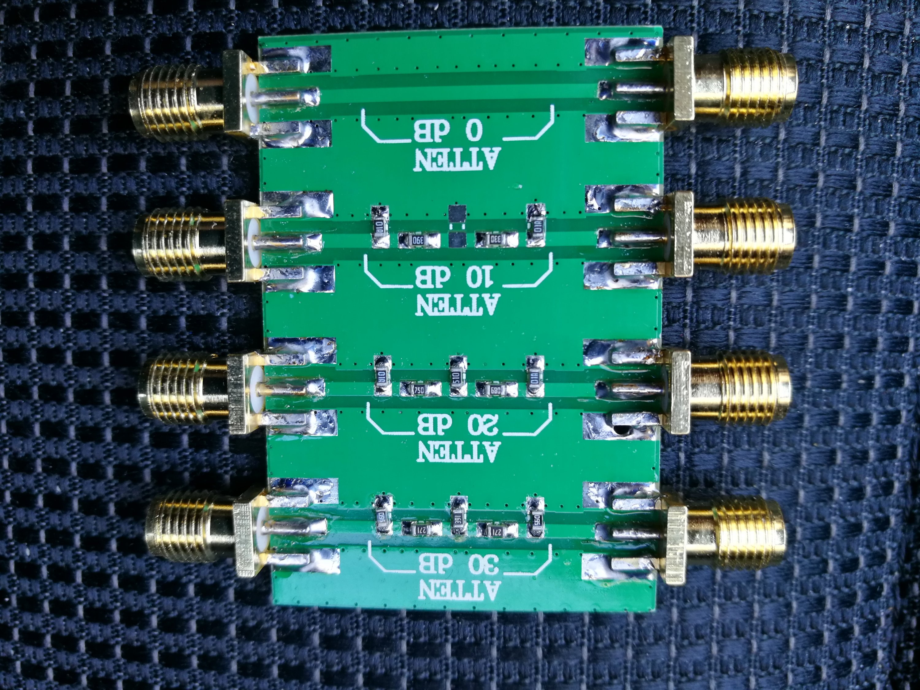
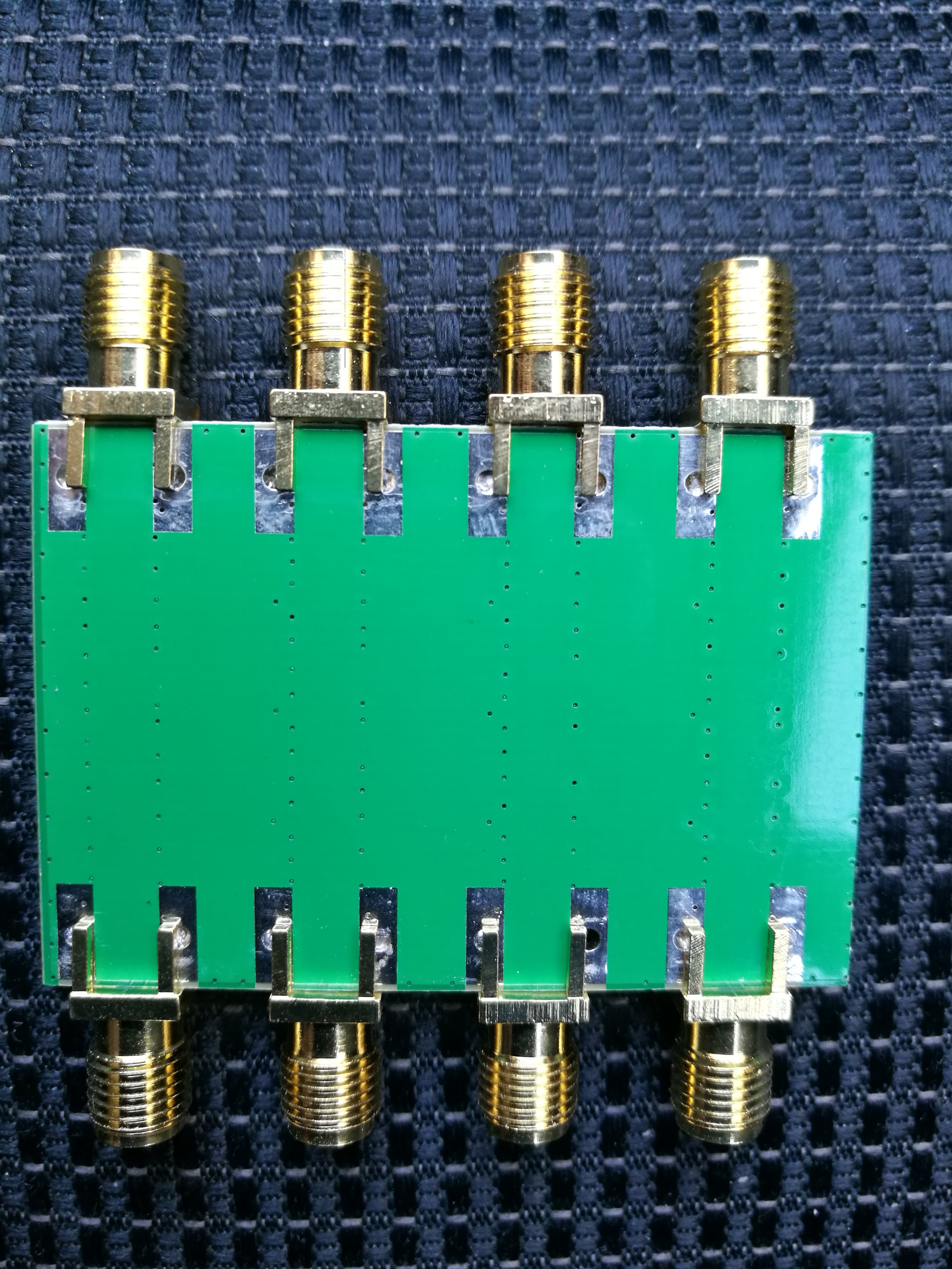
RF attenuators are a universal building block within the RF design arena. I neeeded some RF attenuators for my electronics lab. I found this cheap product DC-4.0GHz RF Fixed Attenuator from Banggood. They seemed to have pretty good specfications and features considering that the price is just slightly over 7 Euros for three attenuators:
Frequency range: DC – 4.0GHz
Maximum power: 23dBm (200mW)
Standing wave ratio: ≤ 1.20
System impedance: 50Ω
RF interface: SMA double female head (Outer screw inner hole)
Attenuation:
Direct: 0dB (reference)
Level 1: 10 ± 0.8 dB
Level 2: 20 ± 1.1 dB
Level 3: 30 ± 1.5dB
This attenuator works great and is accurate.
Did some initial testing with spectrum analyzer with tracking generator.
Worked well as expected up to 1.5 GHz – the highest the instrument I had could go up to.
Good value for the price.
Back
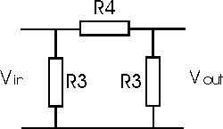
Link if you are interesed in making attenuators yourself, take a look a How to make a RF Attenuator with Resistors – Fixed or Variable article.
3 Comments
Tomi Engdahl says:
A DIY Step Attenuator, By Gluing Together Two Smaller Ones
https://hackaday.com/2019/06/04/a-diy-step-attenuator-by-gluing-together-two-smaller-ones/
In the RF world, attenuators are a useful test and measurement tool. Variable units that can apply different levels of attenuation in discrete steps are even better. [DuWayne] made a 63 dB step attenuator by putting two smaller units in series, with an Arduino Nano in control of them. With a 3D printed enclosure and OLED for feedback, the device is easily adjusted with a single rotary encoder.
63 dB step attenuator UPDATE 5/9/19
https://kv4qb.blogspot.com/2019/04/63-db-step-attenuator.html
I have several digital controlled attenuator modules that I bought one eBay a while ago, and I guess it is time to use some of them.
simplest with only 6 control pins for a total attenuation of 31.5 dB in .5 dB steps. I am going to connect two in series with the control lines paralleled for a total of 63 dB in 1 dB steps.
a 9 volt battery for power. The attenuator module runs on 3.3 volts, but the current draw is low enough that I can power it directly from the 3.3 volt output of the Nano.
It is very simple, with just checking the rotary encoder and incrementing or decrementing the attenuation value by the step size which can be changed by pressing the encoder button.
Also measured insertion loss with it set to 0 dB, and found about a 3 dB loss at all frequencies I am interested in.
Tomi Engdahl says:
6G Digital Programmable Attenuator 30DB Step 0.25DB OLED Display CNC Shell RF Module
https://www.banggood.com/6G-Digital-Programmable-Attenuator-30DB-Step-0_25DB-OLED-Display-CNC-Shell-RF-Module-p-1648810.html?currency=EUR&utm_source=criteo&utm_medium=cpc_brand&utm_content=all&utm_campaign=electronics-emea-en&cur_warehouse=CN
Tomi Engdahl says:
https://www.electronics-tutorials.ws/attenuators/t-pad-attenuator.html
http://www.nu9n.com/tpad-calculator.html