In my Antenna measurements with RF noise source posting I described how antenna measurements can be done with RF noise source, directional coupler and SDR radio (DVB-T stick). To do measurement we connect the noise source to the output of the coupler, the antenna to the input of the coupler and the RTL-SDR dongle to the coupling (CPL) port of the coupler.
Because I did not have a nice 50 ohms directional coupler at the moment and getting one would need some investment (time and money to get one), thought if I had something suitable already.
I found some TV antenna network taps and remember that they are actually directional couplers. The downside with them is that they would be made for 75 ohms impedance and work best only at TV antenna network frequencies (around 40 MHz to 900 MHz or slightly more). But I though that they might be somehow used as directional couplers for 50 ohms antenna measurements if I an lucky. Let’s try to test them. I fortunately had access to some RF measurement instruments to see how those antenna taps work as directional couplers. And I also had antenna to measure (antenna tuned for 450 MHz).
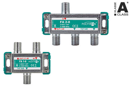
First directional coupler I had: FA 1-8
http://www.polytron.de/index.php/en/splitters-taps-5-1000mhz/230-taps-5-1000-mhz
FA 1-8
Abzweigdämpfung / Tap loss (IN-TAP) 8,5 dB
Durchgangsdämpfung / Through loss (IN-OUT) 2 dB
Entkopplung / Isolation (OUT-TAP) 23 dB
Rückflussdämpfung / Return loss (IN/OUT/TAP) 18 dB
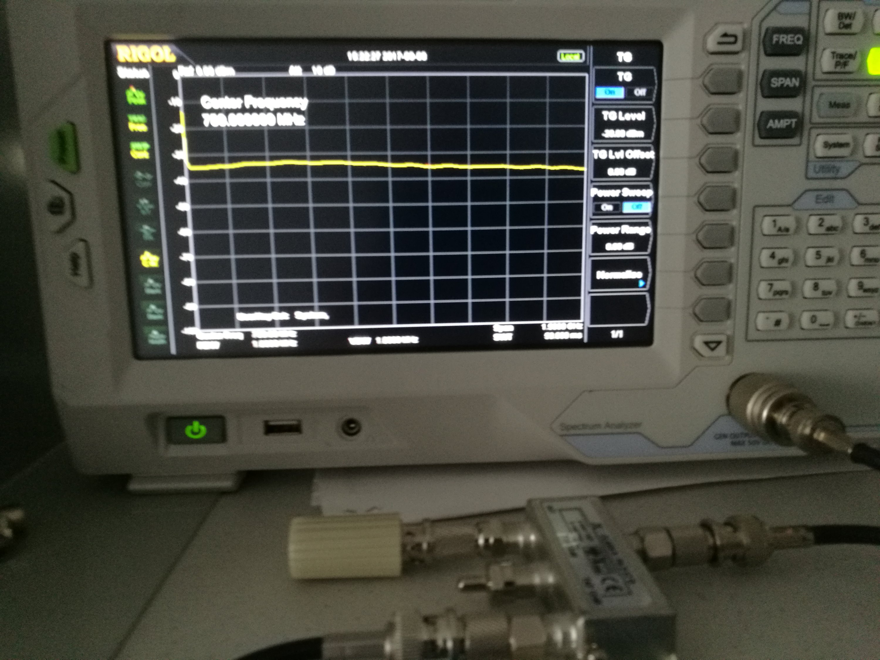
Measurements of this directional coupler on 50 ohms system (50 ohms source, 50 ohms load):
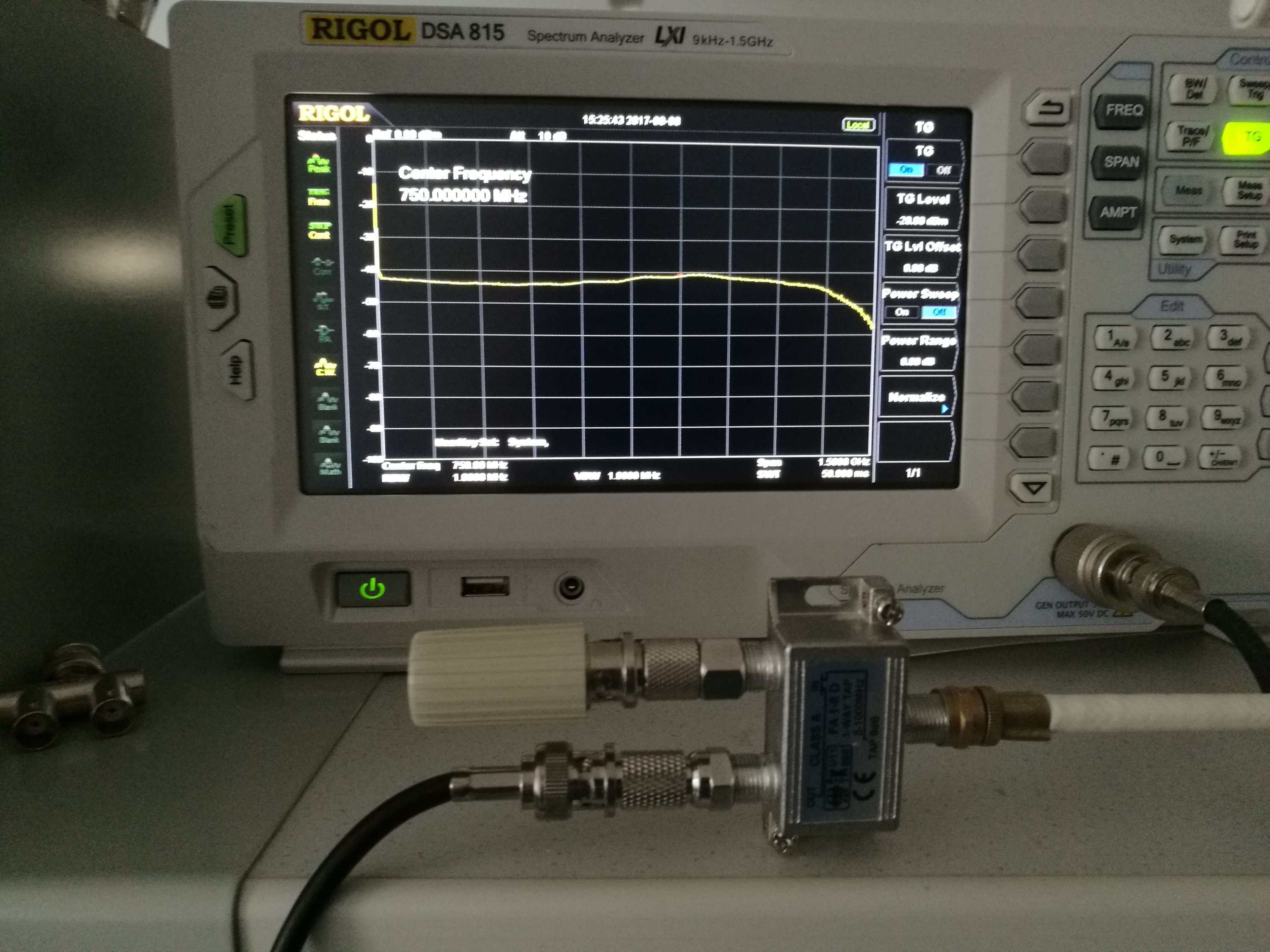
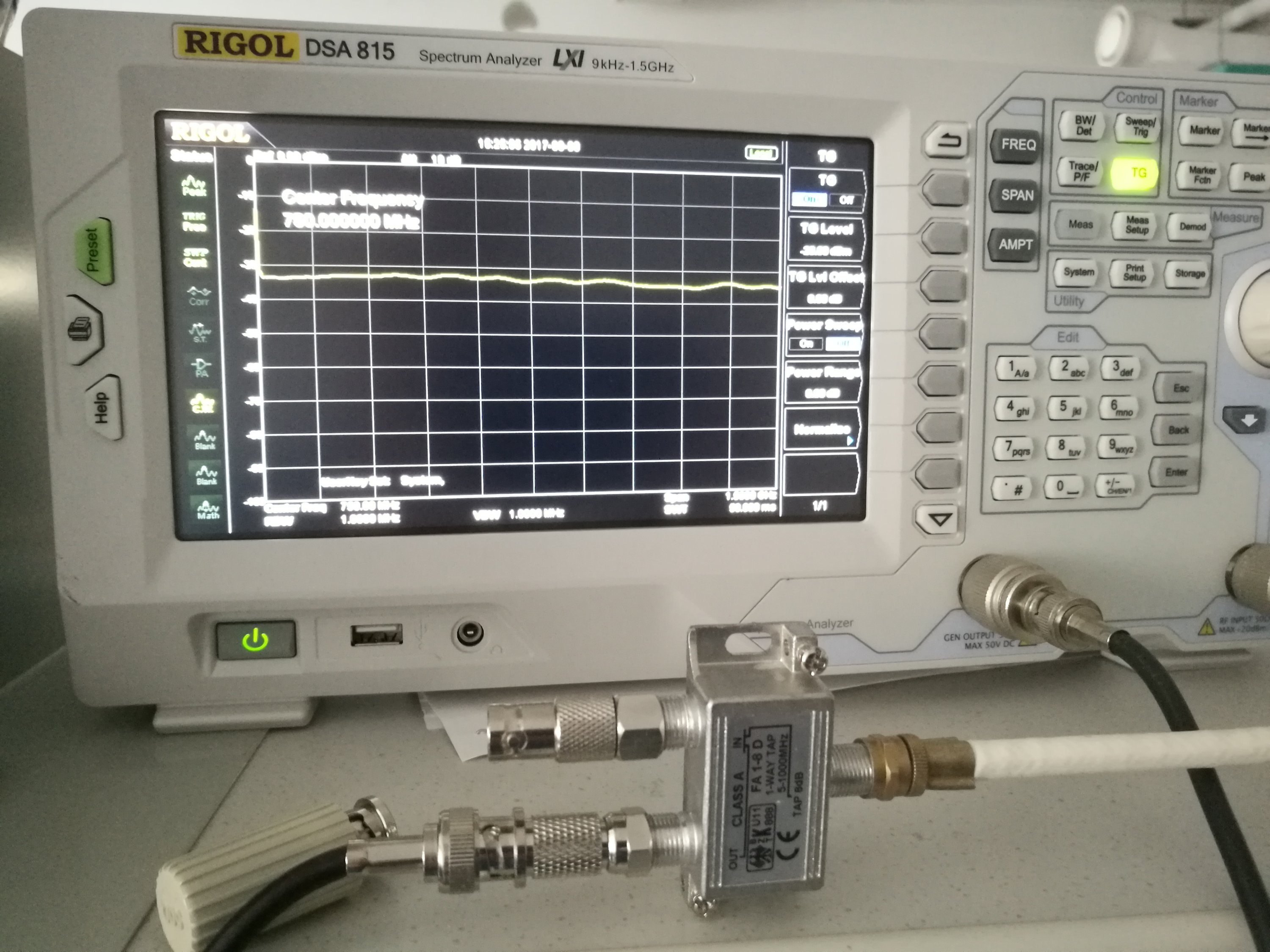
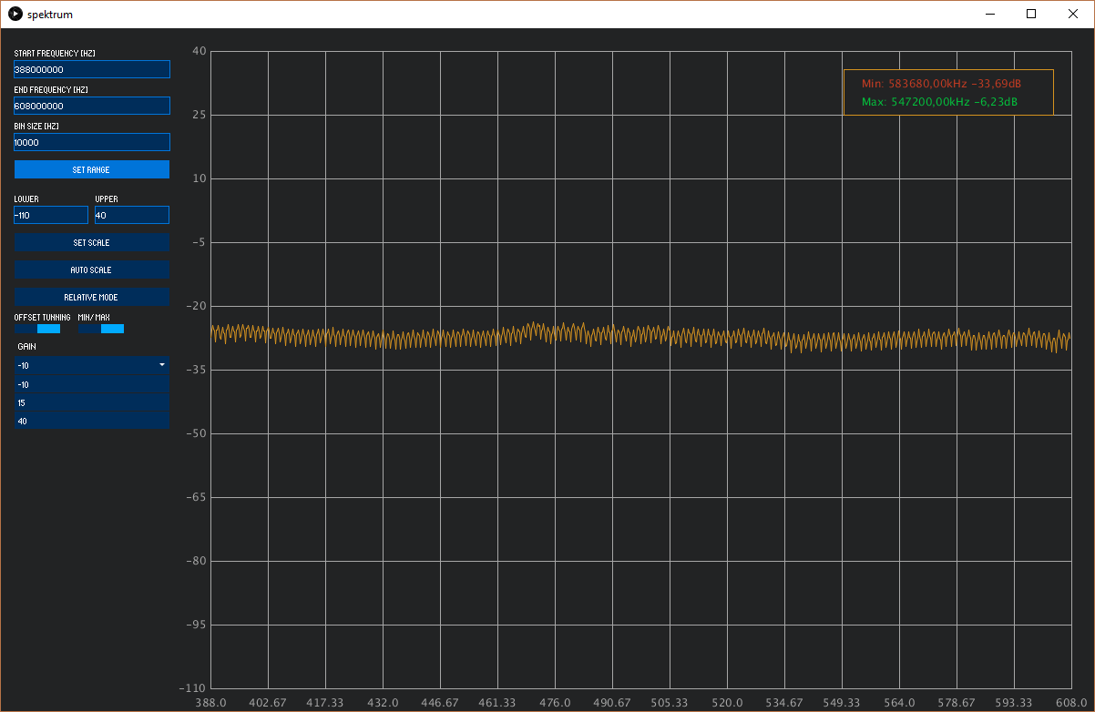
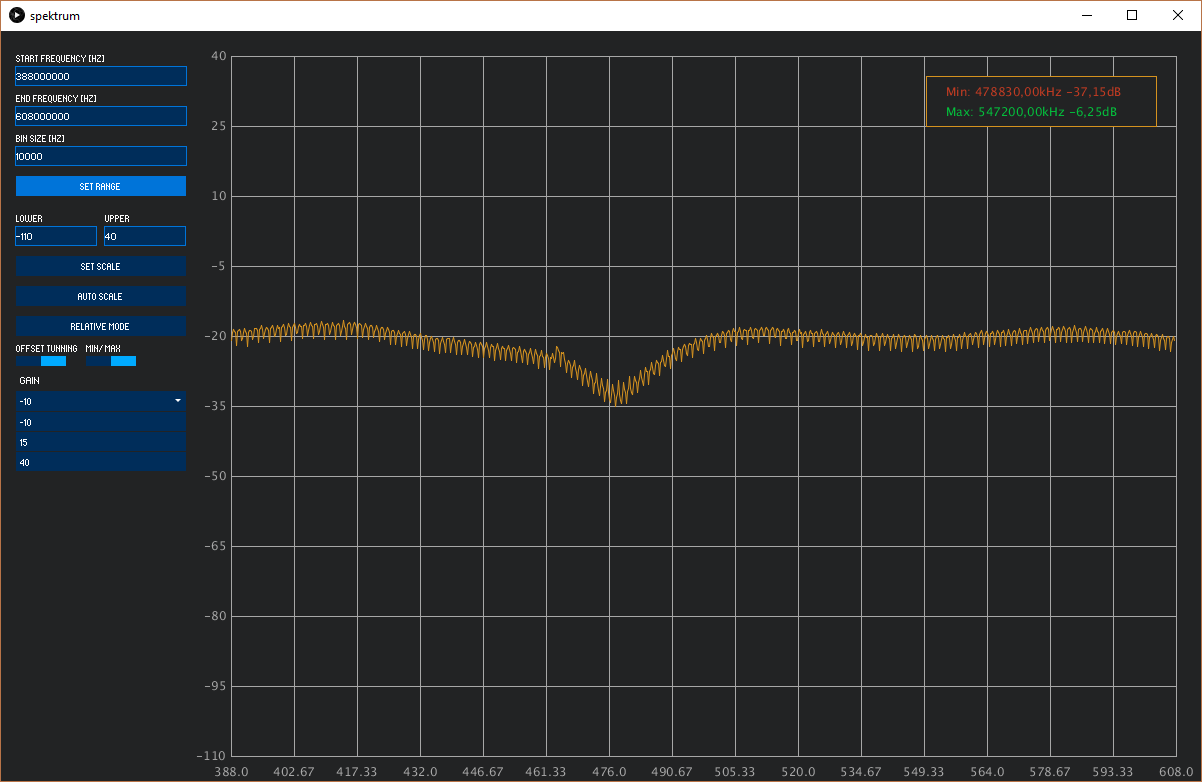
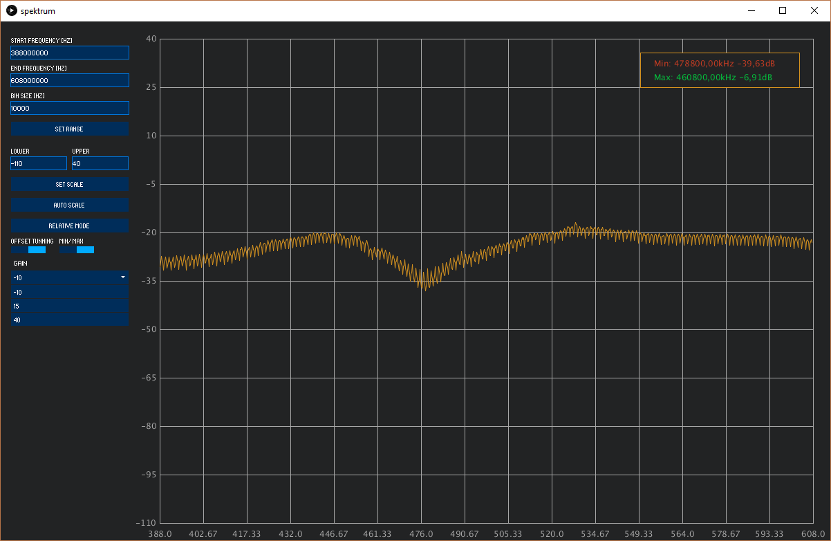
Results with 5o ohms terminator, FA 1-8 and Spektrum RTL-SDR Spectrum Analyzer Software:
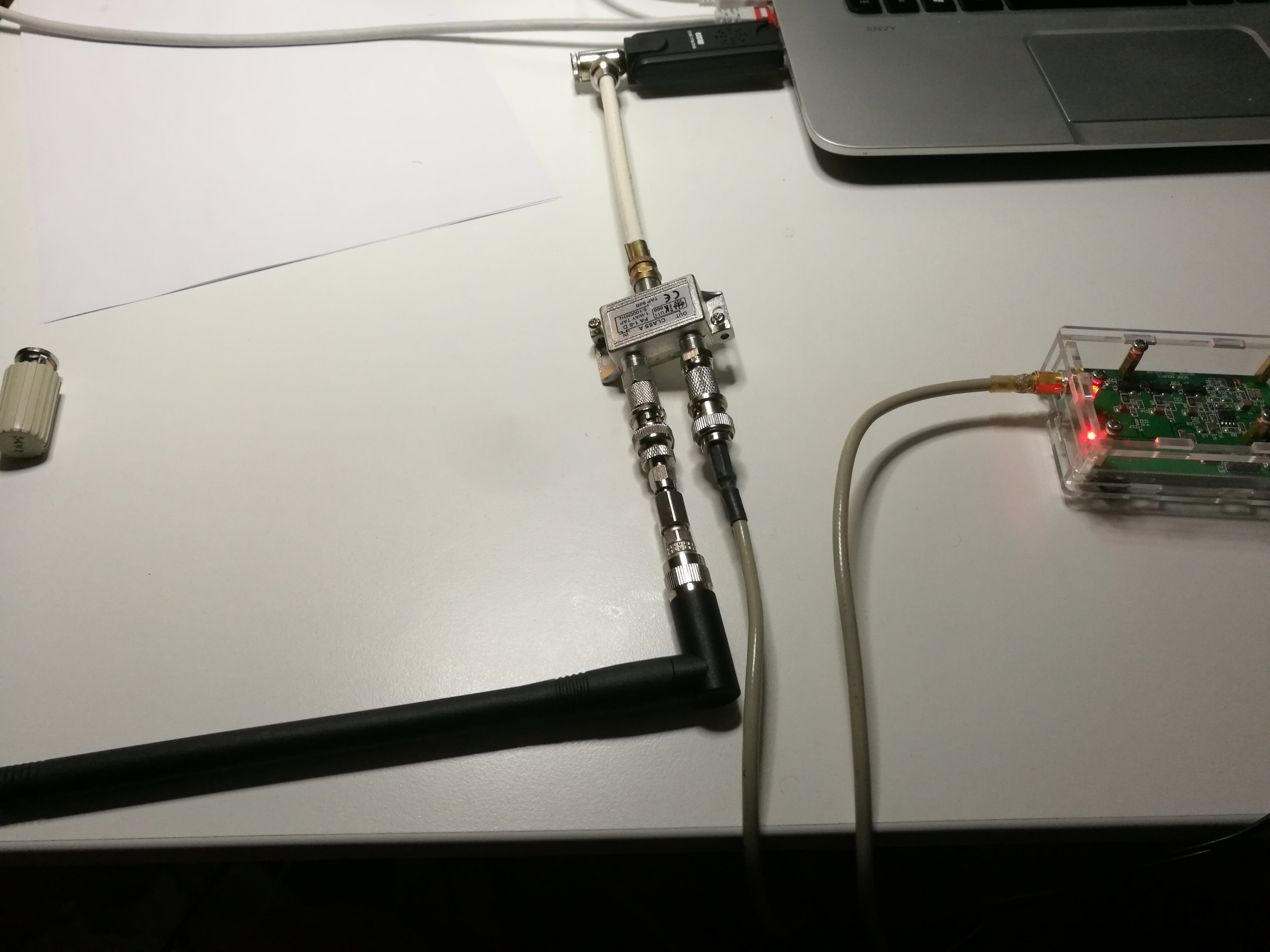
Measurement setup with antenna:
Results with 450 MHz antenna connected:
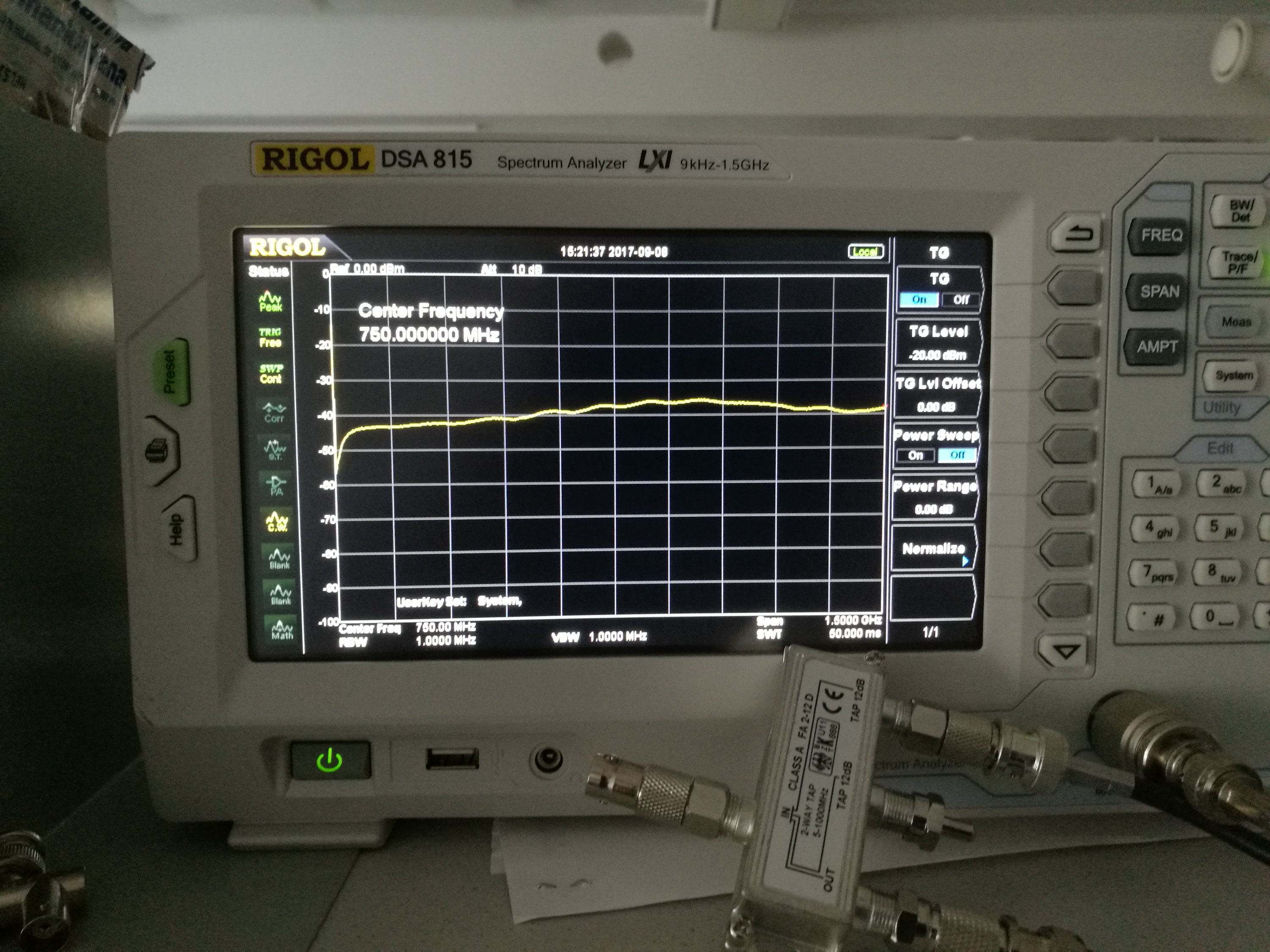
Second directional coupler: FA 2-12
FA 2-12 D
https://www.satpoint.at/produkt-kategorien/verteilertechnik/fa-2-12-d-
Abzweiger/Taps 5-1000 MHz
Technische FA 2-12 D Daten:
- Frequenzbereich: 5-1000 MHz
- 12dB Abzweigedämmpfung
- Schirmungsklasse A
- CE-Prüfzeichen
- Anschlüsse: F-Connectoren
- Massives Gehäuse aus Zink-Spritzguss
- Ein- und Ausgänge brummentstört
1 Signal Eingang
1 Signal Ausgang
2 Signal Abzweigung 12dB

Measurements of this directional coupler on 50 ohms system (50 ohms source, 50 ohms load):
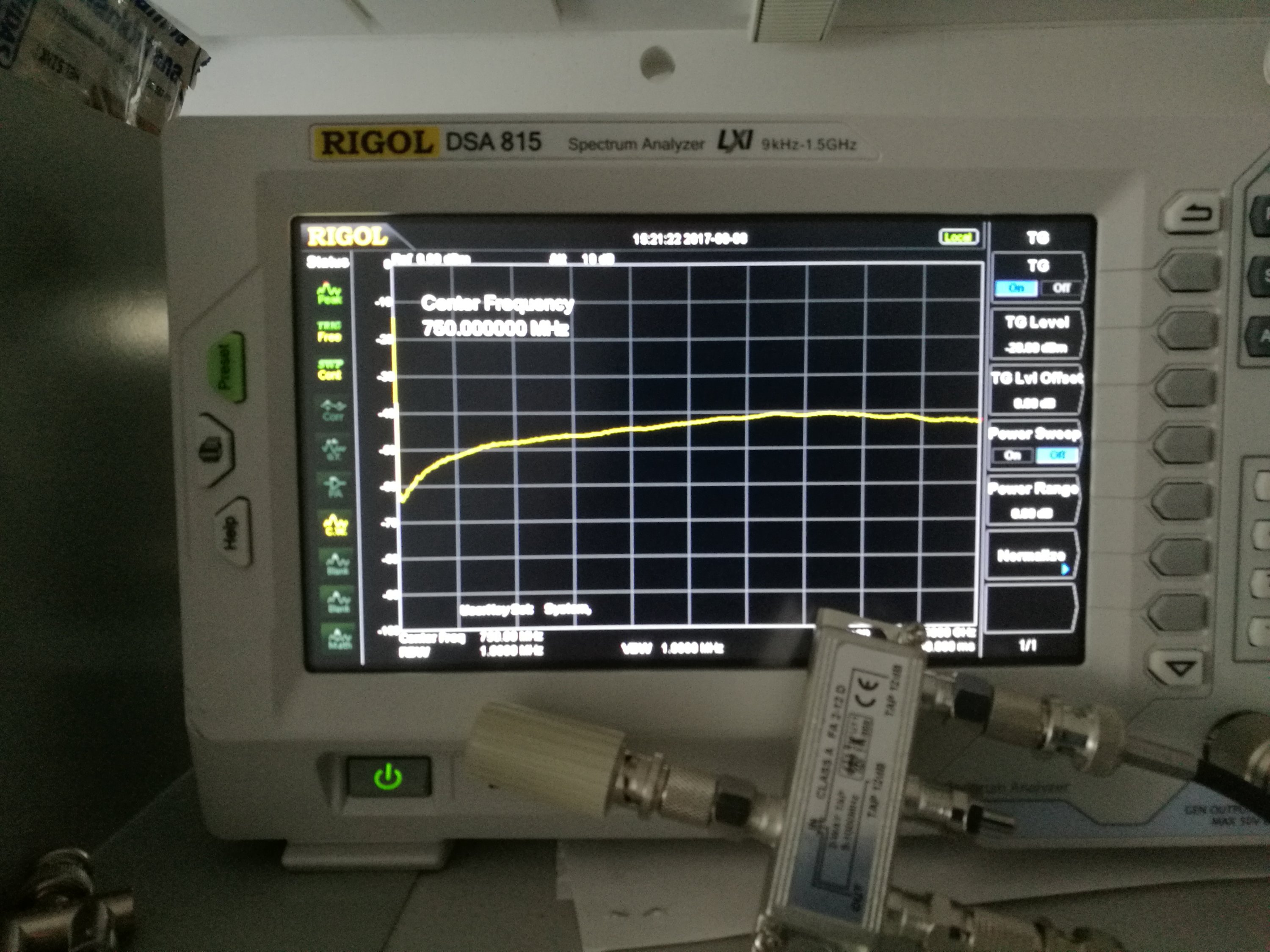
Results with 450 MHz antenna:
End results
The end result was that those antenna taps worked quite acceptably as directional coupler for antenna measurement. They are not ideal, but they are useful tools. In my measurements it seems that the first 8 dB tap was slightly better for this application.
14 Comments
Tomi Engdahl says:
Related posting:
Trying TV signal splitter for antenna measurements
http://www.epanorama.net/newepa/2017/09/10/trying-tv-signal-splitter-for-antenna-measurements/
Juanro says:
http://www.transverters-store.com/rf_bridge/rf_bridge.html
Tomi Engdahl says:
This RF BRIDGE 0.1 – 3000 MHz from
http://www.transverters-store.com/rf_bridge/rf_bridge.html
looks really interesting. I have to test out it.
I ordered one and plan to review it when I receive it.
Tomi Engdahl says:
#158: Directional Coupler Basics & how to sweep SWR of an antenna | Return Loss | VSWR
https://www.youtube.com/watch?v=iBK9ZIx9YaY
This video describes the basic properties and specifications for directional couplers, and shows their basic operation on an oscilloscope. Typical applications are discussed, along with a practical example showing how to sweep the VSWR, or Return Loss, of an antenna using a directional coupler and a spectrum analyzer with a tracking generator. The resulting return loss measurement is compared to the SWR measured on an MFJ-259B antenna analyzer.
Tomi Engdahl says:
Return Loss Bridge-Setup Procedure
https://www.youtube.com/watch?v=Or6HWilY2Pc
In this informational video, Jim Beck at Eagle guides you through the proper procedures for taking antenna measurements using the Eagle Return Loss Bridge.
Tomi Engdahl says:
Return Loss Bridge Basics#
https://www.youtube.com/watch?v=XgZRyID-t8g
Return Loss Bridge Basics !!
https://www.youtube.com/watch?v=v94csA9fuHE
Tomi Engdahl says:
Sweeping Antennas for Return Loss (initial)
https://www.youtube.com/watch?v=X50qybdiLuk
Tomi Engdahl says:
RIGOL DSA815 Spectrum Analyser discovers real-time VSWR of 144MHz 2m antenna… in real time
https://www.youtube.com/watch?v=k2VVtKaysLo
Using RIGOL Spectrum Analyzer and VSWR Bridge to Measure Antenna
https://www.youtube.com/watch?v=INHslyjBxH0
Tomi Engdahl says:
5 Steps to Antenna Matching Using a Portable PC-Based VNA
http://www.mwrf.com/test-measurement/5-steps-antenna-matching-using-portable-pc-based-vna?NL=MWRF-001&Issue=MWRF-001_20180419_MWRF-001_848&sfvc4enews=42&cl=article_1_b&utm_rid=CPG05000002750211&utm_campaign=16788&utm_medium=email&elq2=f2c693c11e064abea6b38a82560daafd
These practical tips outline an efficient way to perform impedance matching with a PC-based vector network analyzer combined with analysis software.
Properly matching an antenna to a transceiver is one of the easiest ways to extend the signal range and battery life of a smartphone, laptop, or any other wireless device. According to the inverse square law of radio waves, only a 6-dB improvement in path loss from improved matching results in a device that transmits and receives at twice the range. A spectrum analyzer with a tracking generator can check an antenna match by looking at the voltage standing wave ratio (VSWR). But the best tool to make the impedance measurements needed to effectively design a matching network is a vector network analyzer (VNA).
Until recently, many engineers tasked with integrating an antenna into a wireless device had limited or no access to a VNA due to the historically high cost of these instruments. In fact, some have not been trained on how to use them. However, the advent of low-cost, portable VNAs coupled with intuitive PC software has made it easier and more affordable to perform antenna matching to improve the performance of wireless devices.
To combat circuit losses, the impedance-matching network in most cases consists of one or more low-loss inductors and capacitors or transmission line stubs. These components are used in a network design chosen to meet the goals of matching impedances, as well as any filtering and bandwidth (or multi-band) specifications as needed.
Step 1: Calibrate the VNA as close to the measurement plane as possible, ideally at the matching-network location.
Step 2: If necessary, align the calibration plane with the measurement plane by using a port extension.
Step 3: Measure the unmatched impedance at the frequency of interest.
Step 4: Determine the matching-network component values and integrate the components.
Step 5: Confirm the matched impedance and adjust if needed.
By following these five steps and using a portable VNA coupled with analysis software, anyone can improve their wireless device’s performance without breaking the bank.
Tomi Engdahl says:
A Journey Through NFC Antenna Tuning Without a VNA
https://blog.hackster.io/a-journey-through-nfc-antenna-tuning-without-a-vna-5cf580913577
https://0xfred.wordpress.com/2018/12/07/nfc-antenna-tuning-without-a-vna/
Tomi Engdahl says:
https://en.wikipedia.org/wiki/Dipole_antenna
Tomi Engdahl says:
Welcome To Antennas 101
July 29, 2021
With a little help from this introductory guide, even non-RF engineers can take advantage of wireless technology.
https://www.electronicdesign.com/technologies/passives/article/21769333/electronic-design-welcome-to-antennas-101?utm_source=EG+ED+Auto+Electronics&utm_medium=email&utm_campaign=CPS220713127&o_eid=7211D2691390C9R&rdx.identpull=omeda|7211D2691390C9R&oly_enc_id=7211D2691390C9R
fFUJuD2xadxzs5 says:
94304 342498 An fascinating discussion is worth comment. I believe which you need to write a lot more on this subject, it may well not be a taboo topic but typically folks are not enough to speak on such topics. Towards the next. Cheers 154872
Tomi Engdahl says:
https://hackaday.com/2024/12/06/antenna-measurement-in-theory-and-practice/