I did some antenna measurement with RTL-DSR with help of directional coupler. Before I realised I had directional coupler, I did some experimenting with antenna signal splitter.
RF splitters are widely used in RF applications. The enable RF power to be split or combined within an environment where the characteristic impedance is maintained.
There are two broad categories of RF proper splitters and one improper:
Resistive power splitters: These power splitters and combiners use resistors. The 6 dB three-port splitter has (ideally) 6.02 dB loss from any one port to any other port. The isolation of a resistive splitter is equal to its insertion loss.
Hybrid power splitters: Hybrid splitters use transformers and are able to provide low levels of loss. A typical signal splitter that split signal from one port to two ports has 3-4 dB of signal loss. The amount of isolation will depend upon the impedance termination at the ports (typically from 6 dB to 30 dB).
T-piece: BNC Ts are not splitters. Power does NOT split evenly at a T connector and impedance matching does not work (part of input signal gets reflected back). Actually it COULD be made to work if the coax lengths are cut just right (would work well in this case just at one frequency), but that likely isn’t the case.
Typical TV signal splitters are designed to equally divide the signals on the input port of the splitter to each of the output ports. A two way TV signal splitter will has approximately 3.5 – 4 dB of loss on each port. Good splitters promise up to around 20 dB of isolation between output ports (bad ones can use resistive power splitter or even worse ones are just direct T piece with no impedance matching). TV antenna splitters are designed to work with 75 ohms impedance level.
Here is a good TV antenna signal splitter I used:
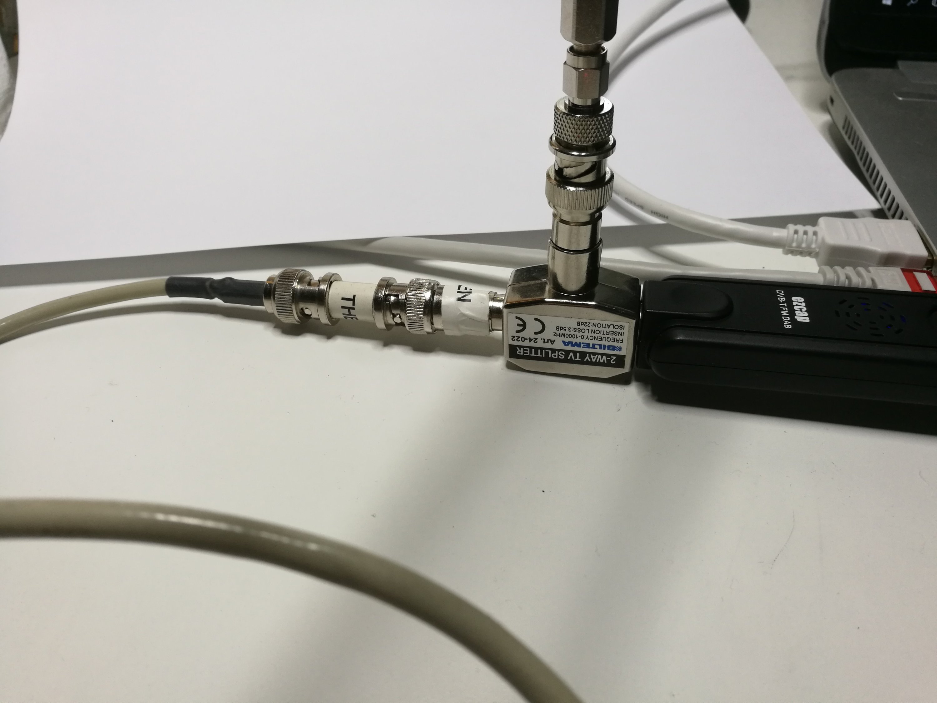
Theoretically the signal splitter should provide around 20 dB of signal output port to another when the “input” port is terminated with nominal impedance (75 ohms). When the impedance on the “input” port of splitter is other than right one (more or less than 75 ohms), there will less signal attenuation from one output port to another, meaning higher signal level gets through from port to another. All the signal picked buy the antenna and all the possible signal reflections from antenna will be split to splitter outputs evenly (3-4 dB attenuation).
The antenna splitter I used was Biltema 24-022 (no longer sold there, they have some newer similar looking models though). Here is data from the device:
Frequency range: 0-1000 MHz
Insertion loss: 3.5 dB
Isolation: 22 dB
In my case I connected the antenna tube measured (nominally 50 ohms) to “input” port, signal generator (50 ohms from gray cable) to one splitter output and other splitter output connected to RTL-SDR (approximately 75 ohms). I expect to get maybe somewhat lower than ideal signal attenuation, but still something that could be used for something. Let’s make some measurements to see how things work.
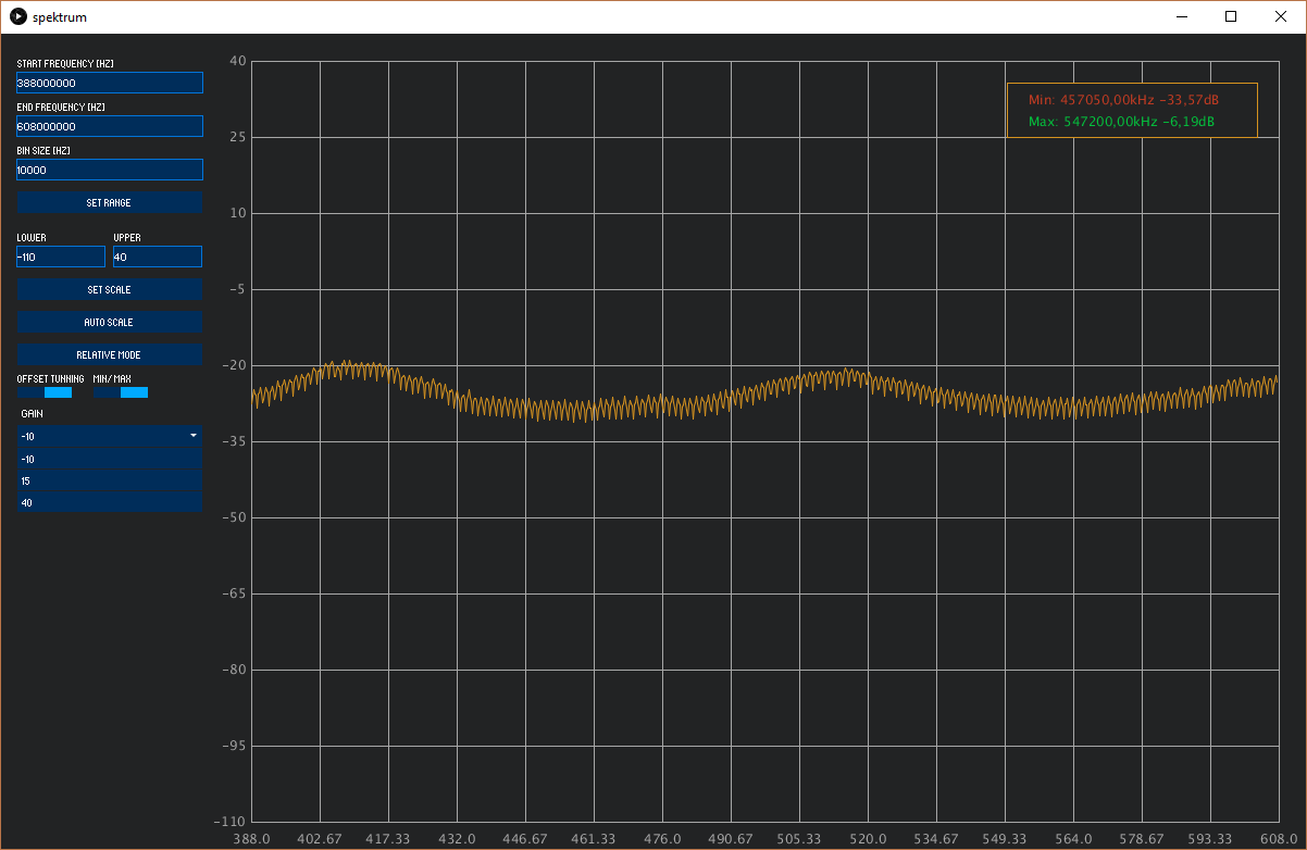
Results 50 ohms
Results qith @450 antenna:
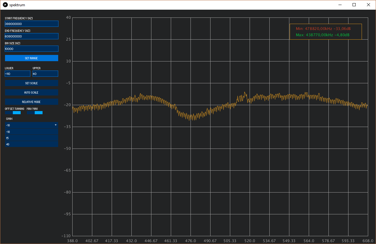
The end results from the test is that the antenna splitter worked so that I could see antenna impedance variations over frequency. But the results I got was worse than what I got with my antenna measurements with directional coupler. So I will stick with using directional coupler. But I know that I might be able to use this kind of antenna splitter in situations where I don’t have directional couplers in hand.
11 Comments
BestRachelle says:
I see you don’t monetize your site, don’t waste your traffic, you can earn additional bucks
every month. You can use the best adsense alternative for any type of website (they approve all websites), for more
details simply search in gooogle: boorfe’s tips monetize your website
Tomi Engdahl says:
RF Isolator: Teardown and Experiments
https://www.youtube.com/watch?v=QtqJU9UjAzM
In this video, I took apart a 8 to 10 GHz microwave RF isolator and did some measurements. High resolution teardown pictures at
http://www.kerrywong.com/2016/03/01/teardown-of-an-8-10-ghz-rf-isolator/
Tomi Engdahl says:
Why You Need Circulators in Repeaters
https://www.youtube.com/watch?v=5kwb1zCZ0KU
A discussion of circulators and a teardown of a 915MHz circulator.
RF Isolator Teardown & Explanation
https://www.youtube.com/watch?v=Whn3QjHUgIw
Ever wonder what’s inside an RF Isolator?
Tomi Engdahl says:
HP 778D Dual Directional Coupler – Tear Down
https://www.youtube.com/watch?v=r-OS3BlRWFs
In this video I take a look at a 778D Dual Directional Coupler that was part of a lot I won at auction – I really wanted 1 but ended up with 6 – 3 of which didn’t pass manufacturer perf test – So I thought I’d take it apart and have a look inside.
Tomi Engdahl says:
#158: Directional Coupler Basics & how to sweep SWR of an antenna | Return Loss | VSWR
https://www.youtube.com/watch?v=iBK9ZIx9YaY
This video describes the basic properties and specifications for directional couplers, and shows their basic operation on an oscilloscope. Typical applications are discussed, along with a practical example showing how to sweep the VSWR, or Return Loss, of an antenna using a directional coupler and a spectrum analyzer with a tracking generator. The resulting return loss measurement is compared to the SWR measured on an MFJ-259B antenna analyzer.
Tomi Engdahl says:
#208: Visualizing RF Standing Waves on Transmission Lines
https://www.youtube.com/watch?v=M1PgCOTDjvI
This video illustrates how RF (radio frequency) standing waves are created in transmission lines – through the addition of the forward (transmitted) wave and the reflected wave that results from improperly terminating the line or matching the load or antenna to the transmission line impedance.
Tomi Engdahl says:
RF and Microwave PCB Design – Part 4: Power Dividers.
https://www.youtube.com/watch?v=FDXBor3SnZ0&feature=youtu.be&mkt_tok=eyJpIjoiWkRJNU5qSTJZamhtWTJFNCIsInQiOiJ1WTc2VHVscWFjeSs4S045ZG5BaW1IY1JcL3puUnplbnJsUExaS0h0OEJPZWVldEk0MnZER0JTamF0RmRTQWpCaEhUemo5UXd1QVZ1QnZcL241OUNUdlJIdzRDMFFGNVhiTEQwM0tXMnViR1wvYjVta2dVYzJac08xNmdaXC9cL2h0b3h4In0%3D
RF and Microwave PCB Design – Transmission Lines and Impedance – Altium Academy
https://www.youtube.com/watch?v=GuJVkZgAloI
Tomi Engdahl says:
Understanding Power Splitter/Combiner Power Handling with Coherent and Non-Coherent Signals
https://blog.minicircuits.com/understanding-power-splitter-combiner-power-handling-with-coherent-and-non-coherent-signals/?utm_campaign=MWRF%20Design%20Elements%20Sept.%202020&utm_source=email&utm_medium=Email&utm_term=Splitters&utm_content=MWRF%20Design%20Elements%20Sept.%202020
A Power Splitter/Combiner is a passive device that can be used for two reciprocal functions: a single signal may be divided into multiple outputs, or in the opposite direction, multiple input signals are combined into a single output. In case of an N-port splitter, the input signal will be divided into N output ports. When used as an N-port combiner, the N inputs will be combined into an output signal from a single port.
Consider a 2-way power splitter. A single signal is the source, which is split into two output signals, each with half the original power (-3 dB). There is no phase difference between the outputs since they are derived from the same input signal. The outputs are thus coherent. If we introduce a time delay in one of the signal paths, such as a section of transmission line, there will be a phase difference, but it will remain constant, so the signals are still coherent. With these coherent signals, the signal paths are balanced and virtually no power is dissipated by the load resistor.
In the other direction — as a power combiner — if the two inputs are coherent and identical in amplitude, the device is balanced and there will be no power in the load resistor. But if there are any differences in the input signals (non-coherent), the system is unbalanced, resulting in power being sent to the load resistor. The amount of power dissipated due to non-coherent combining must not exceed the ratings of the load resistor.
In general, non-coherent signals have differences in amplitude, phase and/or frequency that will result in significant unbalanced power being dissipated. The dissipated power may range from a minor amount to the total input power.
Tomi Engdahl says:
What is a Rat-Race Coupler?
https://www.everythingrf.com/community/what-is-a-rat-race-coupler
A Rat-Race Coupler is a type of RF coupler that is manufactured using microstrips in the shape of a ring/circle. It is a four-port coupler, with each port placed at a distance of one-quarter wavelength (λ) away from the other around the top half of the ring. The bottom half of the ring is three-quarter wavelengths (λ) in length. As seen in the figure below it has three branches which are 90 degree phase shifted from each other and one branch that provides a 270 degree phase shift.
This coupler is quite versitile and can be used as a power combiner by combining two in-phase signals. Or can be used as a power divider to provide two equally split signals that are 180 degrees out of phase of two equally split in-phase output.
Tomi Engdahl says:
Two-way Splitters: A Peek Under the Hood
https://broadbandlibrary.com/rf-signal-level-2/
Tomi Engdahl says:
https://www.w8ji.com/combiner_and_splitters.htm?fbclid=IwZXh0bgNhZW0CMTEAAR2dyd06eRzhVd49k77M-aSeo5kFkQTkvB5ZcrsowIG47DUa2NG8MB6QTvc_aem_AeESUUOgDyrXz9QctK2zu6EleMrY60RK3vqNibZkzJYIxZwbFx9E5fE4FEa-TwdN5EndpmN9wjUBrYMRHzdh2Pov