With PoE (Power over Ethernet) technology, an Ethernet cable can carry power in addition to data. PoE can supply operating voltage to PoE compatible networked devices, such as a WLAN base station, an IP camera, a VOIP phone or IoT device. The original IEEE 802.3af-2003 PoE standard provides up to 15.4 W of DC power (minimum 44 V DC and 350 mA) supplied to each device. Current IEEE standards can handle maximum power up to 30 watts and non-standardized solutions up to 60 watts.
New IEEE 802.3bt standard that will be completed in 2018 will increase maximum power to almost 100 watts (71 watts to powered device available). I have written an article on the new PoE standard to Uusiteknologia magazine issue 01/2018.
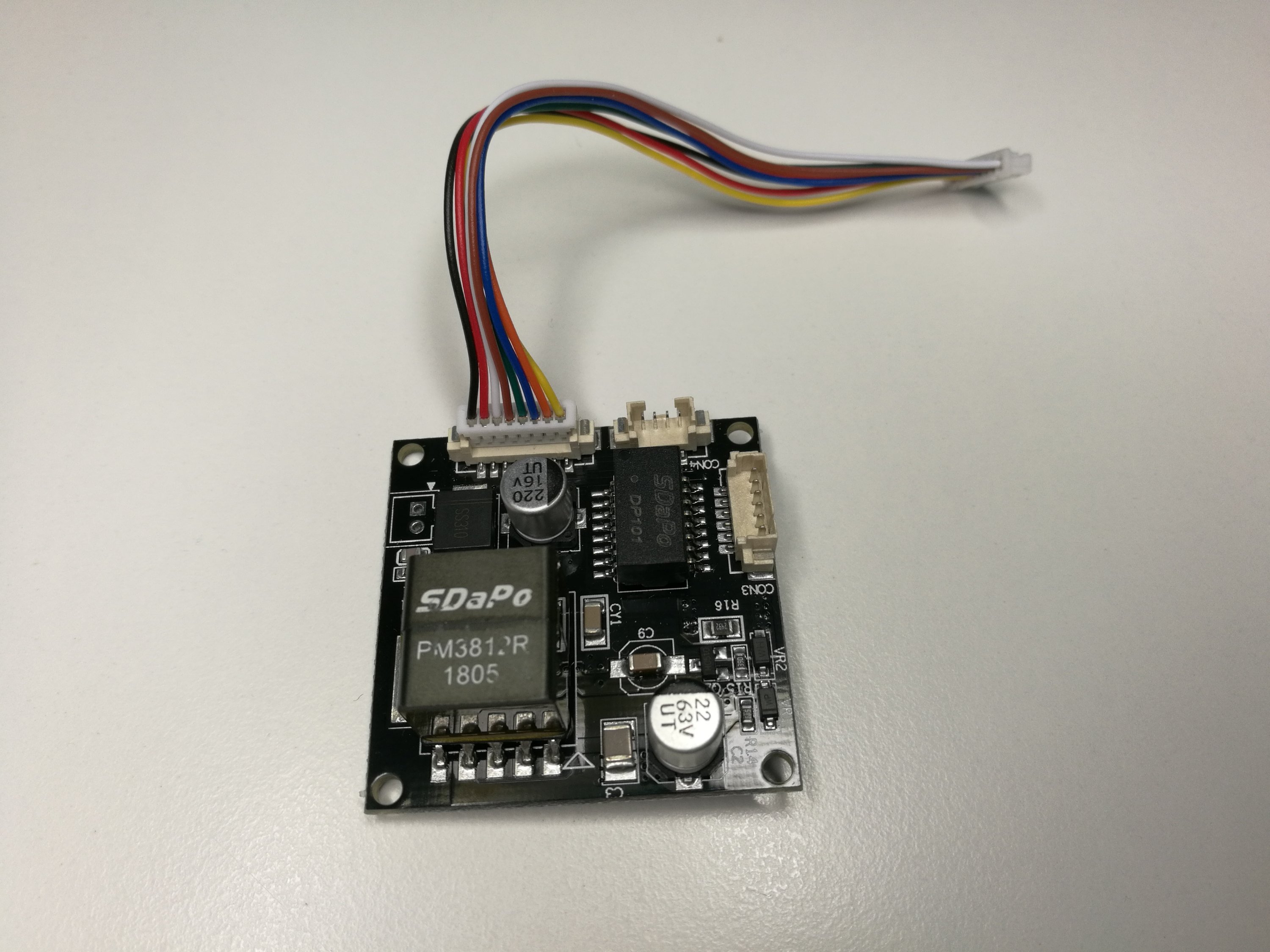
In testing technology for the article I tested some PoE devices. I already wrote an PoE tester teardown. I tried to build my own PoE power supplying circuit (it did not work as planned and finally put out smoke). Then I got one Zyxel power supply. Then built some test PoE powered devices (few LEDs). And finally I received this 1500V PM3812R Male Isolated POE Module for All Network Cameras power supply:
 |
1500V PM3812R Male Isolated POE Module for All Network Cameras |
Here are the product specifications from product page and my comments on them:
1. Specification: meet IEEE802.3af standard, grade class 0 – means that this can output maximum 12.95W of power (minus the losses, expect around 1A 12V on output) and does not specify how much power is really needed
2. Security: have a perfect short circuit protection circuit, 1500V high voltage isolation - standard defines that you need to have this level of isolation as for Ethernet signals that is 1500V isolation
3. Size: 38 x 38mm, suitable for IPC internal integration design – pretty small size
4. Integrated network filter, suitable for all IPC modules – this device is designed to be power supply for IP Camera module
5. Compatibility: support End-span (1,2+/3,6-) and Mid-span (4,5+/7,8-) two modes of power supply – good that supports both standard powering variations
6. Working temperature: -20 degree to 65 degree stable work – quite useful temperature range in celsius
The module comes with two page wiring diagram + datasheet.
The price is pretty reasonable around 4 euros. This device is clearly a module designed to be integrated inside some network camera. But as such this looks like this could be useful for DIY applications.
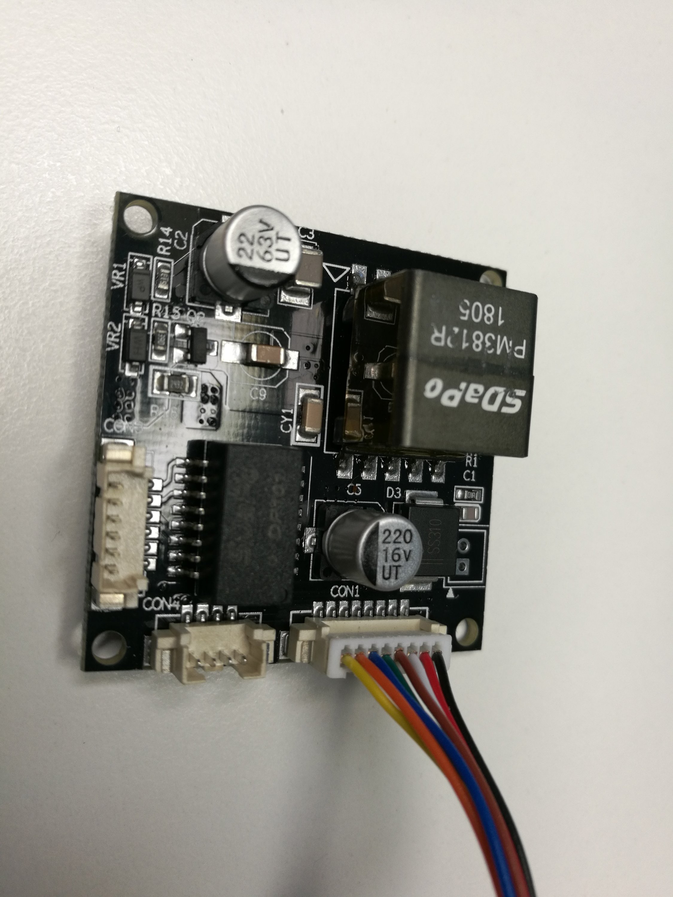
Here is close-up to the component side of the module. On the bottom left there is Ethernet transformer. On the upper right corner there is the switch mode power supply power isolation transformer that is used for converting 37-57V voltage to isolated 12V together with the control IC and handful of other components.
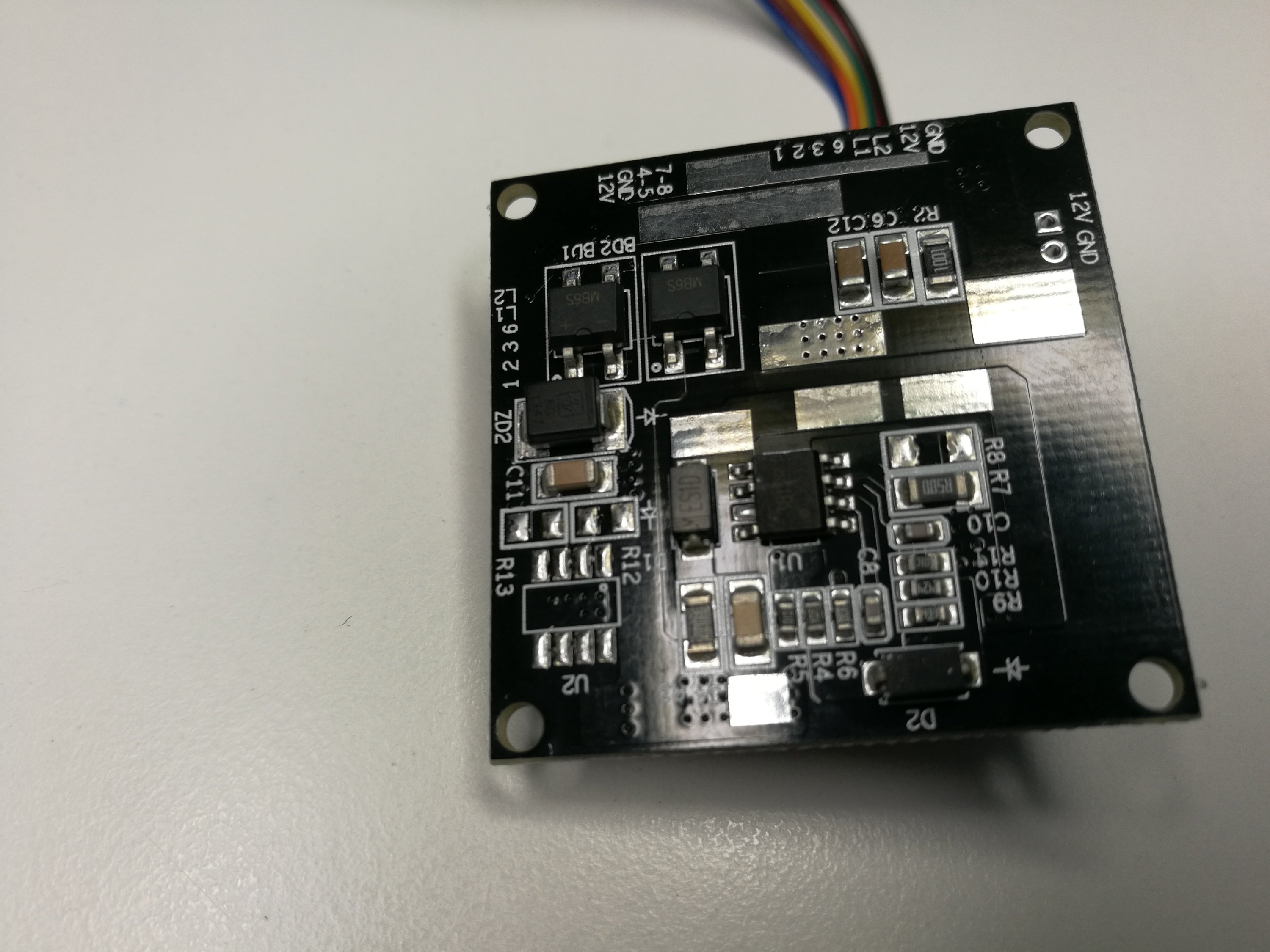
On the bottom side the main active components are two M86S bridge rectifiers (top left) and the main control IC (on the center) with marking 3812R. It is nice that there are clear markings for different connector pins. The connectors on the top left corner are designed to be connected to RJ-45 connector and most numbers refer to pins numbers in it. In addition there is input for external 12V input. On the right side there is 12V output. The connector that has colorful wires on it is designed to be connected to network camera motherboard (which I don’t have).
For testing I soldered wires for the 12V output. Because I did not have suitable cable set I could plug to power in connector, I had to solder two wire-wrap wires directly to the connector pins.
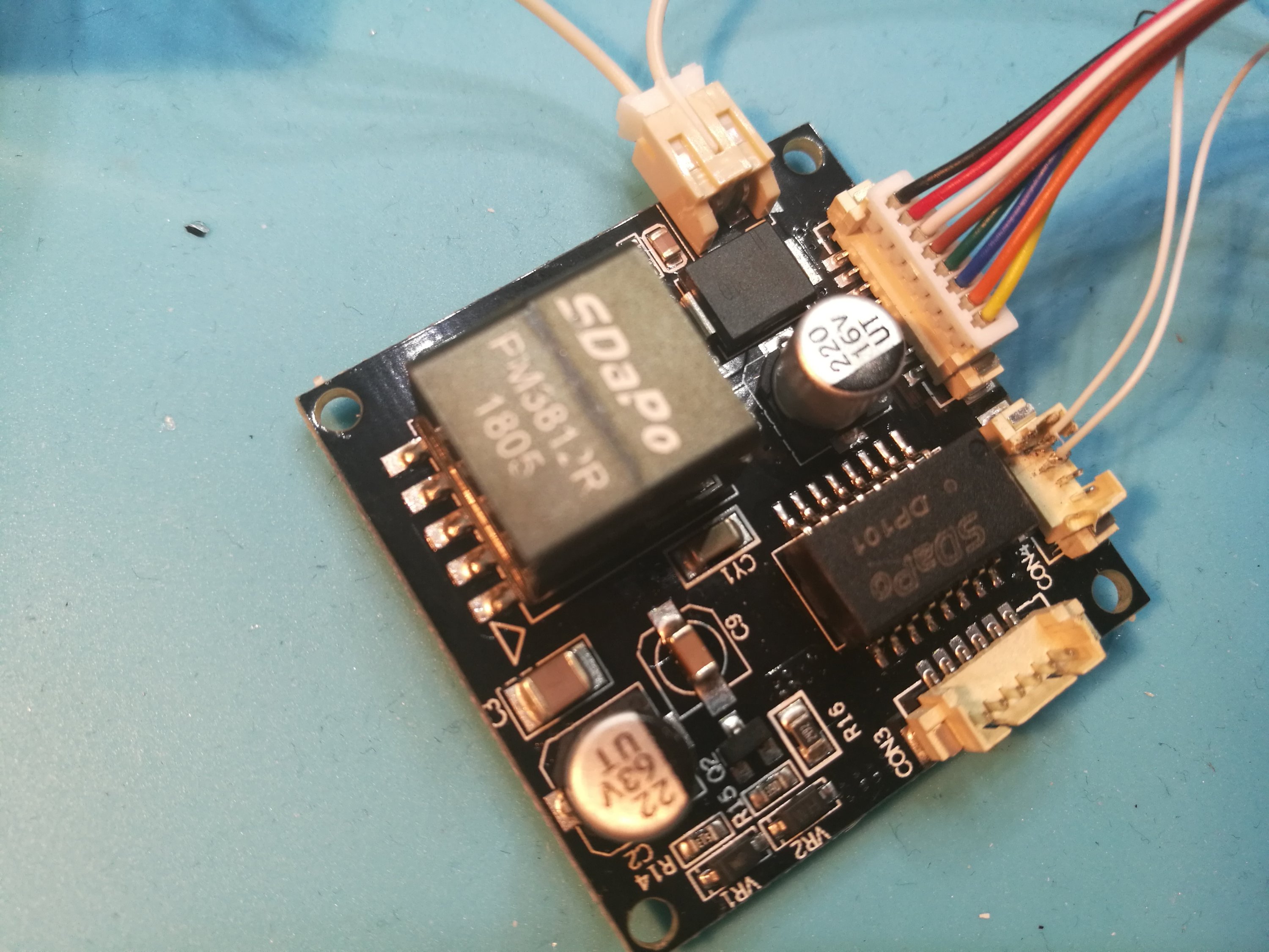
Here is the final test setup for testing.
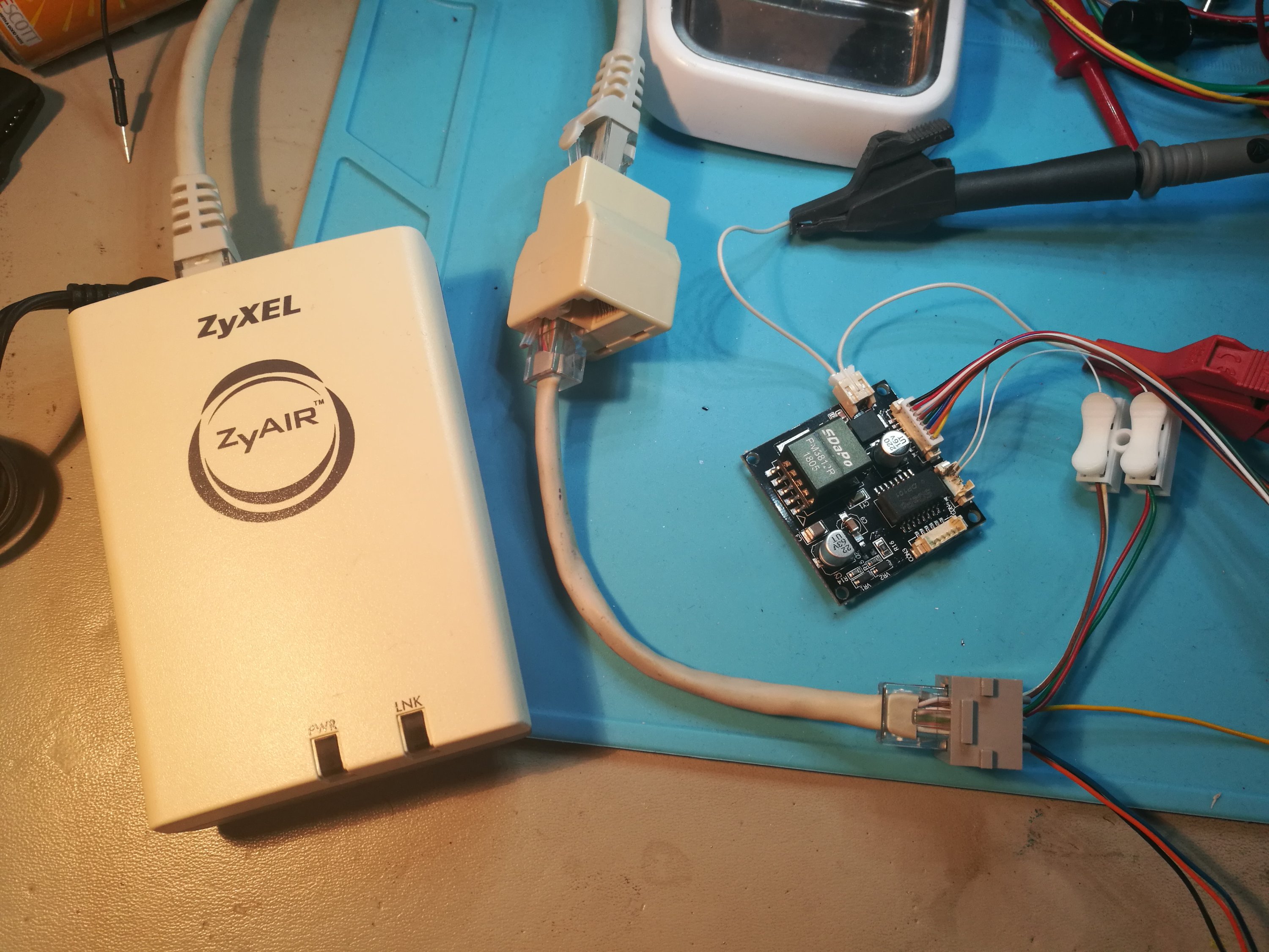
The power supply worked pretty well.The PSE could nicely detect it and start to send power to it through Ethernet wiring. I could use this PSU module to power few watts 12V light bulb nicely. If I tried to connect too powerful load, the power feeding to output stopped. The output voltage was pretty close to 12V. The data sheet promises up to 1A current from it.
I also did some testing on isolation capabilities of this circuit. I measured the isolation between Ethernet side and 12V output side, and I got “open circuit” reading with insulation resistance meter at 250V, 500V and 1000V test voltages.
It seems that this 1500V PM3812R Male Isolated POE Module for All Network Cameras seems to be do well that it promises to do. The downside is that this module has tiny special connectors for which I don’t have suitable wire set (I don’t know where to get).
5 Comments
Tomi Engdahl says:
Power Over Ethernet Splitter Improves Negotiating Skills
https://hackaday.com/2018/08/24/power-over-ethernet-splitter-improves-negotiating-skills/
Implementing PoE is made interesting by the fact that not every Ethernet device wants power; if you start dumping power onto any device that’s connected, you’re going to break things. The IEEE 802.3af standard states that the device which can source power should detect the presence of the device receiving power, before negotiating the power level. Only once this process is complete can the power sourcing device give its full supply. Of course, this requires the burden of smarts, meaning that there are many cheap devices available which simply send power regardless of what’s plugged in (passive PoE).
[Jason Gin] has taken an old, cheap passive PoE splitter and upgraded it to be 802.3af compatible (an active device).
Upgrading a passive Power over Ethernet splitter with 802.3af compatibility
https://ripitapart.com/2018/08/22/upgrading-a-passive-power-over-ethernet-splitter-with-802-3af-compatibility/
The DWL-P200 is a near-ideal candidate for conversion to 802.3af/at (I’ll call it “active PoE” from now on) since it already uses 48 volts for power – all it really needs is an active PoE-compatible front-end which requires an Ethernet isolation transformer, two diode bridges, a TVS (transient voltage suppression) diode, a 802.3af PD controller chip (and a partridge in a pear tree?). Easy enough, right… right?
The actual front-end was built as two separate boards: the first was the power input board; the second was the 802.3af active PoE PD controller, which had its own construction considerations
The power input board is pretty simple and was comprised of two Bourns CD-HD201 60-volt Schottky diode bridges and a SMAJ58A 58-volt TVS surge suppression diode to help overcome voltage spikes that can occur when a cable is unplugged due to the inductance in the cable itself.
The second board is the PoE PD controller, which is responsible for negotiating with the 802.3af/at PSE controller at the other end of the cable. I used the Texas Instruments TPS2378 PoE PD controller, which was meant for 802.3at Class 4 (25.5 watts maximum) but I’m only using it for 802.3af Class 0 (up to 12.95 watts).
With the active PoE upgrades installed, the splitter now works with 802.3af, 802.3at and passive 48 volt PoE power sources. However, the internal construction of the splitter means it only supports 10/100 Mbps Ethernet. Additionally, I find that the board gets very hot under full load
Tomi Engdahl says:
Cheap Power Over Ethernet For The ESP32
https://hackaday.com/2019/02/05/cheap-power-over-ethernet-for-the-esp32/
While most projects we see with the ESP32 make use of its considerable wireless capabilities, the chip can be connected to the wired network easily enough should you have the desire to do so. [Steve] liked the idea of putting his ESP32s on the wired network, but found the need for a secondary power connection burdensome. So he took it upon himself to modify some cheap Power Over Ethernet (PoE) hardware and create a single-cable solution (Google Translate).
[Steve] bought a PoE module intended for security cameras and ran a close eye over the board to figure out what kind of hardware it is was using to generate the nominal 12 V output.
https://geeks-r-us.de/2019/02/03/esp32-mit-poe-fuer-unter-10e/
https://translate.google.com/translate?sl=auto&tl=en&u=https%3A%2F%2Fgeeks-r-us.de%2F2019%2F02%2F03%2Fesp32-mit-poe-fuer-unter-10e%2F
Tomi Engdahl says:
Powering your raspberry pi-3/4 over ethernet cable(length upto 100Meters), It uses Passive PoE mechanism where T568b wire color
Blue/Blue-White ==> +(positive) terminal of DC supply
Brown-White/Brown ==> -(negetive) terminal of DC supply
https://albert-david.blogspot.com/2019/09/poor-mans-poe-for-raspberry-pi-3-under-2.html?m=1
Tomi Engdahl says:
Poor man’s PoE for Raspberry pi-3/4 under ~$2
http://albert-david.blogspot.com/2019/09/poor-mans-poe-for-raspberry-pi-3-under-2.html
Tomi Engdahl says:
PixPoE: Putting Plenty of Pixels Wherever You Can Plumb Some Cat5!
Glen Akins’ project is a solid reference for anyone looking to implement a PoE+-powered device.
https://www.hackster.io/news/pixpoe-putting-plenty-of-pixels-wherever-you-can-plumb-some-cat5-9a8f24c3b485